
USER MANUAL

Special Thanks
DIRECTION
Frederic BRUN Philippe CAVENEL
HARDWARE DEVELOPMENT
Marc ANTIGNY
Claire BOUVET
Thierry HAUSER
Jérome LAURENT
Léonard SAUGET
SOFTWARE DEVELOPMENT
Timothée BEHETY
Pierre PFISTER
Baptiste AUBRY
Simon CONAN
Corentin COMTE
DESIGN
Martin DUTASTA Morgan PERRIER Axel HARTMANN
TESTING
Arnaud BARBIER
Germain MARZIN
Matthieu COUROUBLE
Christophe TESSA
Ludovic CIALDELLA
Benoît GRELIER
BETA TESTING
Luca LEFEVRE
Terry MARSDEN
Ken Flux PIERCE
Chuck ZWICKY
Jay JANSSEN
Ben EGGEHORN
Boele GERKES
Marco CORREIA
Randall LEE
Philippe BUTTOZ
Guillaume COLLART
Grégory ROUDGÉ
AUDIOFUSE CONTROL CENTER MANUAL
Randall LEE (author)
Minoru KOIKE
Vincent LE HEN
Camille DALEMANS
Charlotte METAIS
Jose RENDON
Holger STEINBRINK
Jack VAN
AUDIOFUSE STUDIO MANUAL
Leo Der Stepanians
(author)
Minoru KOIKE
Vincent LE HEN
Camille DALEMANS
Charlotte METAIS
Jose RENDON
Holger STEINBRINK
© ARTURIA SA – 2020 – All rights reserved.
26 avenue Jean Kuntzmann
38330 Montbonnot-Saint-Martin
FRANCE
www.arturia.com
Information contained in this manual is subject to change without notice and does not
represent a commitment on the part of Arturia. The software described in this manual is
provided under the terms of a license agreement or non-disclosure agreement. The software
license agreement specifies the terms and conditions for its lawful use. No part of this
manual may be reproduced or transmitted in any form or by any purpose other than
purchaser’s personal use, without the express written permission of ARTURIA S.A.
All other products, logos or company names quoted in this manual are trademarks or
registered trademarks of their respective owners.

Product version: 1.0
Revision date: 17 March 2020

Important Safety Instructions
PRECAUTIONS INCLUDE, BUT ARE NOT LIMITED TO, THE FOLLOWING:
1. Read and understand all the instructions.
2. Always follow the instructions on the device.
3. Before cleaning the device, always remove the USB and DC cable. When
cleaning, use a soft and dry cloth. Do not use gasoline, alcohol, acetone,
turpentine or any other organic solutions; do not use a liquid cleaner, spray or
cloth that's too wet.
4. Do not use the device near water or moisture, such as a bathtub, sink, swimming
pool or similar place.
5. Do not place the device in an unstable position where it might accidentally fall
over.
6. Do not place heavy objects on the device. Do not block openings or vents of the
device; these locations are used for air circulation to prevent the device from
overheating. Do not place the device near a heat vent at any location with poor
air circulation.
7. Do not open or insert anything into the device that may cause a fire or electrical
shock.
8. Do not spill any kind of liquid onto the device.
9. Always take the device to a qualified service center. You will invalidate your
warranty if you open and remove the cover, and improper assembly may cause
electrical shock or other malfunctions.
10. Do not use the device with thunder and lightning present; it may cause electrical
shock.
11. Do not expose the device to hot sunlight.
12. Do not use the device when there is a gas leak nearby.
13. Arturia is not responsible for any damage or data loss caused by improper
operation of the device.
Specifications subject to change:
The information contained in this manual is believed to be correct at the time of printing.
However, Arturia reserves the right to change or modify any of the specifications without
notice or obligation to update the hardware that has been purchased.
IMPORTANT:
The product and its software, when used in combination with an amplifier, headphones or
speakers, may be able to produce sound levels that could cause permanent hearing loss.
DO NOT operate for long periods of time at a high level or at a level that is uncomfortable. If
you encounter any hearing loss or ringing in the ears, you should consult an audiologist.
NOTICE:
Service charges incurred due to a lack of knowledge relating to how a function or feature
works (when the product is operating as designed) are not covered by the manufacturer’s
warranty, and are therefore the owner's responsibility. Please study this manual carefully
and consult your dealer before requesting service.

Thank you for purchasing an AudioFuse!
Each member of the AudioFuse family is a cutting-edge, pro audio interface with stellar
sonic quality, an intuitive workflow, and a high return on your investment. They provide the
superior sound of high-end analog studio consoles with all of the flexibility and connectivity
you need for any recording or performance.
At the core of each device is Arturia's proprietary DiscretePRO® technology, which set
new standards in audio excellence and affordability. For the technically-minded, there's a
comprehensive description of the DiscretePRO® specifications here.
This manual covers the features and operation of Arturia’s AudioFuse Control Center,
the companion software for the AudioFuse family. For additional information about the
hardware, please read the owner's manual for your device.

Introduction
Dear musician,
We’d like to thank you for purchasing one of the members of our AudioFuse family! These
audio interfaces are anything but ordinary; they have been constructed using components
of the utmost quality so as to achieve recordings of the utmost quality. This level of crystal
clarity is unprecedented in their price range!
This manual will help you make the most of your AudioFuse device by using the AudioFuse
Control Center, the powerful companion software we designed to work with the entire
AudioFuse series.
The AudioFuse Control Center does much more than simply give you another way to tweak
the front panel controls; it also provides access to parameters and routing options that are
not available from the front panel.
If you are reading this manual and have not already downloaded the AudioFuse Control
Center, you can find it here: AudioFuse Control Center.
Be sure to visit the www.arturia.com website for information about all of our other great
hardware and software instruments. They have proven time and again to be the go-to
solutions for musicians around the world.
Musically yours,
The Arturia team

Table Of Contents
1. AudioFuse Studio.......................................................................................................................................................... 3
1.1. Overview ...................................................................................................................................................................................... 3
1.1.1. Box Contents...................................................................................................................................................................................................................... 3
1.1.2. DiscretePRO® certificate........................................................................................................................................................................................... 3
1.1.3. Register your AudioFuse Studio .......................................................................................................................................................................... 4
1.2. Hardware Features............................................................................................................................................................... 4
1.2.1. Top View .............................................................................................................................................................................................................................. 4
1.2.2. Front View ...................................................................................................................................................................................................................... 10
1.2.3. Back View.......................................................................................................................................................................................................................... 11
1.3. Getting started....................................................................................................................................................................... 13
1.3.1. Powering your AudioFuse Studio..................................................................................................................................................................... 13
1.3.2. Setting your Operating System ........................................................................................................................................................................ 13
1.3.2.1. Setup on macOS ........................................................................................................................................................................................................................................................................................................ 13
1.3.2.2. Set up on Windows................................................................................................................................................................................................................................................................................................. 14
1.3.2.3. Set up on iPad/iPhone .......................................................................................................................................................................................................................................................................................... 14
1.3.2.4. Set up on Android..................................................................................................................................................................................................................................................................................................... 14
1.3.3. The AudioFuse Control Center........................................................................................................................................................................... 15
1.4. How to use AudioFuse Studio...................................................................................................................................... 16
1.4.1. How to record with a microphone................................................................................................................................................................... 16
1.4.2. How to record a synth, guitar or other instrument............................................................................................................................... 17
1.4.3. Inserting external effects into your signal path .................................................................................................................................... 18
1.4.3.1. About TRS to Dual-TS Cables.............................................................................................................................................................................................................................................................................. 18
1.4.4. Re-Amping .................................................................................................................................................................................................................... 20
1.4.5. Use one headphone for Cue, and one for Main..................................................................................................................................... 21
1.4.6. Use AudioFuse to switch between 2 sets of active speakers...................................................................................................... 22
1.4.7. Connect to AudioFuse Studio with Bluetooth .......................................................................................................................................... 23
1.4.8. Use AudioFuse Studio without a computer.............................................................................................................................................. 24
1.4.9. Using Phones 2 to Control Speaker B.......................................................................................................................................................... 24
1.4.10. Loopback Mode........................................................................................................................................................................................................ 24
1.4.11. Talkback on ADAT 1-2.............................................................................................................................................................................................. 24
1.4.12. SPDIF Out from Speaker.................................................................................................................................................................................... 25
1.4.13. AUX outputs from Inputs 1-4 (and DAW) ................................................................................................................................................. 25
1.5. An in-depth look at AudioFuse Studio................................................................................................................... 26
1.5.1. Input Paths in Detail................................................................................................................................................................................................. 26
1.5.1.1. Input Channels 1 - 4 ................................................................................................................................................................................................................................................................................................. 26
1.5.1.2. Inputs 5 - 6..................................................................................................................................................................................................................................................................................................................... 27
1.5.1.3. Inputs 7 - 8 .................................................................................................................................................................................................................................................................................................................... 28
1.5.1.4. Digital inputs ................................................................................................................................................................................................................................................................................................................ 29
1.5.2. Monitor Mixing and Routing .............................................................................................................................................................................. 30
1.5.3. Creating a Monitor Mix ......................................................................................................................................................................................... 30
1.5.4. Routing Monitor Mixes to speakers and headphones...................................................................................................................... 30
1.5.5. USB Audio mapping ................................................................................................................................................................................................. 31
1.5.5.1. Audio Mapping at 44.1 / 48 kHz sampling rates: ................................................................................................................................................................................................................................... 31
1.5.5.2. Audio Mapping at 88.2 / 96 kHz sampling rates:................................................................................................................................................................................................................................ 32
1.5.5.3. Audio Mapping at 176.4 / 192 kHz sampling rates:............................................................................................................................................................................................................................. 32
1.5.6. Clock Synchronization ........................................................................................................................................................................................... 33
1.5.6.1. Using the Internal Clock....................................................................................................................................................................................................................................................................................... 33
1.5.6.2. Using External Clock Sources.......................................................................................................................................................................................................................................................................... 34
1.6. Specifications........................................................................................................................................................................ 35
2. AudioFuse Control Center.................................................................................................................................... 38
2.1. Welcome to AudioFuse Control Center!............................................................................................................... 38
2.2. Overview................................................................................................................................................................................. 38
2.2.1. The Main window...................................................................................................................................................................................................... 38
2.2.1.1. Two-way communication ................................................................................................................................................................................................................................................................................... 38
2.2.1.2. Basic operations....................................................................................................................................................................................................................................................................................................... 39
2.2.2. The AudioFuse Studio window....................................................................................................................................................................... 40
2.2.2.1. AudioFuse Studio controls not in AFCC ................................................................................................................................................................................................................................................... 40
2.3. The Menu bar....................................................................................................................................................................... 42
2.3.1. The Arturia menu ...................................................................................................................................................................................................... 42
2.3.1.1. Resize Window........................................................................................................................................................................................................................................................................................................... 42

2.3.1.2. AFCC Manual.............................................................................................................................................................................................................................................................................................................. 43
2.3.1.3. About................................................................................................................................................................................................................................................................................................................................ 43
2.3.2. Device Selection........................................................................................................................................................................................................ 44
2.3.3. Device Status .............................................................................................................................................................................................................. 44
2.3.4. Device Settings .......................................................................................................................................................................................................... 45
2.3.4.1. Audio Settings............................................................................................................................................................................................................................................................................................................ 45
2.3.4.2. Preferences............................................................................................................................................................................................................................................................................................................... 50
2.3.5. Firmware Updates................................................................................................................................................................................................... 52
2.4. The Main Window ............................................................................................................................................................. 53
2.4.1. Input zone...................................................................................................................................................................................................................... 53
2.4.1.1. Analog Inputs.............................................................................................................................................................................................................................................................................................................. 53
2.4.1.2. Digital Inputs .............................................................................................................................................................................................................................................................................................................. 54
2.4.2. Monitoring Mix zone ............................................................................................................................................................................................... 55
2.4.2.1. The Channel display.............................................................................................................................................................................................................................................................................................. 55
2.4.2.2. The Master level fader......................................................................................................................................................................................................................................................................................... 56
2.4.3. Output zone.................................................................................................................................................................................................................. 59
2.4.3.1. Analog Outputs ......................................................................................................................................................................................................................................................................................................... 59
2.4.3.2. Digital Outputs......................................................................................................................................................................................................................................................................................................... 60
2.4.3.3. Loopback section ..................................................................................................................................................................................................................................................................................................... 61
3. Software License Agreement............................................................................................................................ 62
4. Declaration of Conformity .................................................................................................................................. 64

1. AUDIOFUSE STUDIO
1.1. Overview
1.1.1. Box Contents
• AudioFuse Studio Advanced Audio Interface
• "Worldwide" power supply with interchangeable leads
• 2x USB cables (USB-C to USB-C, USB-C to USB-A)
• 2x MIDI Adaptors
• Quick Start Guide
• Registration card with Serial and Unlock Code
• DiscretePro® certificate
1.1.2. DiscretePRO® certificate
Your AudioFuse Studio comes with 4 preamplifiers using our DiscretePRO® technology
to ensure the best audio quality when recording. Your AudioFuse Studio is unique and
therefore it comes with its own Audio Precision certificate as a guarantee of its
performance.
A version of this certificate with more details is available after registration on
www.arturia.com/register
Arturia - User Manual AudioFuse Studio - AudioFuse Studio 3

1.1.3. Register your AudioFuse Studio
Be sure to register your AudioFuse Studio as soon as possible! There is a sticker in the Quick
Start Guide and on the bottom panel of the product that contains the serial number of your
unit and an unlock code. These are required during the online registration process. You may
want to record these elsewhere or take a photo of the sticker in case it becomes damaged.
Registering your AudioFuse Studio provides the following benefits:
• Free software license for the AudioFuse Creative Suite, an ever-evolving
collection of software effects and instruments that will let you add your own
unique signature to your music
• Access to the latest version of the AudioFuse Control Center software
• Special offers restricted to AudioFuse Studio owners
1.2. Hardware Features
1.2.1. Top View
A1. Input control section (Input Channel 1-4): This section contains all features relating
to AudioFuse Studio's Input Channels 1-4 with their pristine DiscretePro preamplifiers. The
controls and indicators on are identical on all four channels and are as follows:
4 Arturia - User Manual AudioFuse Studio - AudioFuse Studio

• Mic/Line/Inst Indicators: One of these LEDs automatically illuminates when you
plug in a sound source into AudioFuse Studio's front panel inputs.
◦ If an XLR cable is plugged in,
Mic
is illuminated and all microphone-
related functions become available on the buttons below (
48V
,
Pad
,
Boost
and
Phase Invert
).
◦ If a 1/4" cable is plugged in, the
Line
or
Inst
LED illuminates and
you can switch between modes by pressing the "Inst" button. Again,
only the appropriate options are made available on the buttons below
(
Inst
,
Pad
and
Phase Invert
).
• Gain: This knob sets the input gain of the channel's DiscretePro preamplifier. Use
each channel's VU-meter to ensure your gain levels are set properly.
• VU-Meter: These LEDs indicate the level of the incoming signals after the
DiscretePro preamplifier. Use this in conjunction with the Gain knob to make sure
your levels are set properly. Ideally your incoming signal should peak between
the -10 and -6dB LEDs. If you are seeing the Clip LED light up then reduce the
input gain to prevent clipping (unwanted distortion).
♪: Some high output devices may require engaging the Pad to prevent clipping (see below).
Arturia - User Manual AudioFuse Studio - AudioFuse Studio 5

• 48V: This button engages and disengages 48V phantom power for microphones
requiring power. Note that this button only works when an XLR cable is plugged
into AudioFuse Studio. The button is ignored when 1/4" devices (Instrument or
Line-level) are plugged in, or when nothing is connected to the XLR connector.
• Inst: This button lets you toggle between Line and Instrument modes. Line
mode accepts standard line-level signals provided by most audio devices
(synthesizers, drum machines, studio and HiFi gear, etc.) Instrument mode
changes the impedance of the 1/4" instrument input to Hi-Z (high impedance).
This is designed to be used with instruments that have passive pickups, such
as electric guitars and basses, stringed instruments (mandolin, violin, etc.), and
electric pianos (reed or tine-based). If you're connecting an instrument like the
ones described, activate Inst mode for the best possible sound.
♪: If your instrument has "active" electronics or you're using an external preamp or stomp box before
recording the signal with AudioFuse Studio, you may not need to use Inst mode at all. Feel free to
experiment and see if you notice an improvement in your sound.
• Pad: This button engages and disengages input gain padding, which reduces
the incoming signal levels by 20 dB before they reach AudioFuse Studio's
preamplifier. Switch this on when recording high output instruments or
microphones that overload the AudioFuse Studio's preamplifier even at minimum
gain settings.
!: AudioFuse Studio has a hidden microphone Boost mode that can be switched on by holding
down the Pad button for one second (the button will be illuminated in red when Boost mode is active).
This is is a special mode that provides +10 dB
extra
gain to incoming microphone signals and can be
handy when using microphones with low outputs (such as the popular Shure SM7B, for example) or
when recording very faint sounds. If your microphone has a reasonable output level (most modern
microphones do) then we recommend leaving Boost off to ensure the best possible sound. Note that
this mode is only available when XLR microphones are connected and it cannot be engaged when 1/4"
devices are connected.
• Phase Invert: This button inverts the phase of the incoming signal. Phase
inversion is very useful in certain situations, such as when you are using two
or more microphones to record an instrument. For example, let's say you are
recording a guitar amp with a microphone that is close to the speaker and
another microphone that is placed further away to capture the sound of the
room. You may notice that certain frequencies are being overemphasized (or
de-emphasized) due to phase cancellation caused by the spacing between
the microphones. If so, try pressing the Phase button on just one of your
channels (not both). By inverting the signal on one of your microphones, you
may immediately resolve the phase cancellation issue. If this does not provide
satisfactory results, you will need to move the room mic to a slightly different
location.
A2. Listen Button: This button lets you listen to a specific Input Channel (or multiple Input
Channels) without distraction by muting audio coming from the computer.
6 Arturia - User Manual AudioFuse Studio - AudioFuse Studio

This functionality lets you really focus in and hear what is being recorded without having
to hear anything else. Press the button to switch Listen mode on and off. The button is
illuminated when the mode is active.
♪: The functionality of this button can be adjusted in the AudioFuse Control Center application under
Settings (Gear Icon) > Audio Settings > Listen button. Please refer to the AudioFuse Control Center section
for more information: here [p.45].
A3. Phones Control Section: This section contains two identical sets of controls pertaining to
the headphone outputs on the front panel (see callout B2).
• Level Knob: This knob sets the level for its associated headphone outputs.
• Mono Button: This button engages and disengages Mono mixdown mode for
its associated headphone output. When switched on, the button is lit and the
headphone mix is heard in mono. When switched off, the mix is heard in stereo
(or as recorded)
♪: Being able to quickly monitor in mono can be a very useful feature in both recording and mixing
situations. While recording, singers sometimes prefer to perform with headphones only on one ear so
that they can hear themselves better. A mono mix ensures that the singer hears everything in the mix
even if they are only using one ear to hear playback. During a mixing session, many engineers check
for spectral balance and phase problems by listening to a mono mix. In both cases, the Mono button
provides an easy way to temporarily monitor in mono.
Arturia - User Manual AudioFuse Studio - AudioFuse Studio 7

• Cue Select Buttons: These buttons select the audio source for the headphone
output by stepping through the three mix sources:
Cue 1
,
Cue 2
, and
Main
. These
mixes can be edited in the AudioFuse Control Center application. Please refer to
the AudioFuse Control Center User Manual to learn how to do this.
A4. Talkback: AudioFuse Studio contains a small "talkback" microphone inside its case. This
convenient feature lets you easily communicate with your performer if he/she is in another
room during the recording process. To use this feature, simply hold the Talkback button and
start talking. The built-in microphone can then send your voice to the talent's headphones
(or other destination of your choosing) so that the performer can hear your comments or
instructions from the control room. The level and routing of the talkback microphone can
be configured in the AudioFuse Control Center software under Settings (Gear Icon) > Audio
Settings > Talkback. Please refer to the AudioFuse Control Center section [p.45] for more
information.
Please note the Talkback uses Analog Input 8. It is possible to set TalkBack mode to avoid activating
the Talkback if the Input 8 is already in use. Please refer to the AudioFuse Control Center section for
more information:here [p.45].
A5. Output Section: This section contains controls pertaining to the speaker outputs. Here you
will find things like a master volume knob, VU meters, and other switching, routing, muting
and dimming functions.
• Master Volume Knob: This encoder sets the loudness of the active set of speakers.
Note that Speakers A and B can be adjusted independently or linked so that
loudness differences are maintained when switching back and forth. Linking
functionality is described in the AudioFuse Control Center application. Please
refer to that application's User Manual [p.45] to learn more.
• VU Meters: By default, these LED meters display the loudness level of incoming
mixes (Main, Cue 1, or Cue 2) or any Input channels that have "Listen" mode
engaged. When adjusting the Master Volume knob, these LEDs temporarily turn
blue to show the position of the knob from minimum (bottom) to maximum (top).
• Dim: Pressing this button reduces the speaker level and is commonly used when
having discussions or taking a phone call. By default, the sound level is reduced
by 20 dB but this can be adjusted in the AudioFuse Control Center application.
• Mute: This button mutes the output being sent to the speakers.
• Mono: This button switches on Mono mixdown mode. When switched on, the
button is lit and the mix is downmixed to mono.
8 Arturia - User Manual AudioFuse Studio - AudioFuse Studio
♪: During a mixing session, many engineers like to perform a "mono compatibility" check to ensure
that mixes will translate well onto mono sources (like many phones, laptops or portable Bluetooth
speakers). It is also easier to spot spectral balance problems and phase-related issues in mono. The
Mono button provides an easy way to ensure a mix will translate well.
• Speaker Selector: This button lets you easily A/B your mix on two different sets
of speakers. The currently active speaker is indicated by its corresponding LED.
• Main / Cue 1 / Cue 2 buttons: These three buttons select which mix is sent to
your speakers. The three mixes can be adjusted in the AudioFuse Control Center
software. Please refer to that application's User Manual [p.30] to learn more.
A6. Bluetooth Button: This button switches Bluetooth functionality on and off. When switched
on, the button is illuminated and the Bluetooth audio stream is decoded by the AudioFuse
Studio. The AudioFuse Studio is discoverable by Bluetooth enabled devices like your
smartphone or tablet. This allows you to wirelessly connect to AudioFuse Studio so you can
play music through the studio's sound system. The routing of incoming Bluetooth signals
can be configured in the AudioFuse Control Center software under Settings (Gear Icon) >
Audio Settings > Bluetooth. Please refer to the AudioFuse Control Center User Manual [p.45]
for more information.
!: A long press on the Bluetooth button resets the on-going connection and enables pairing with a
new device.
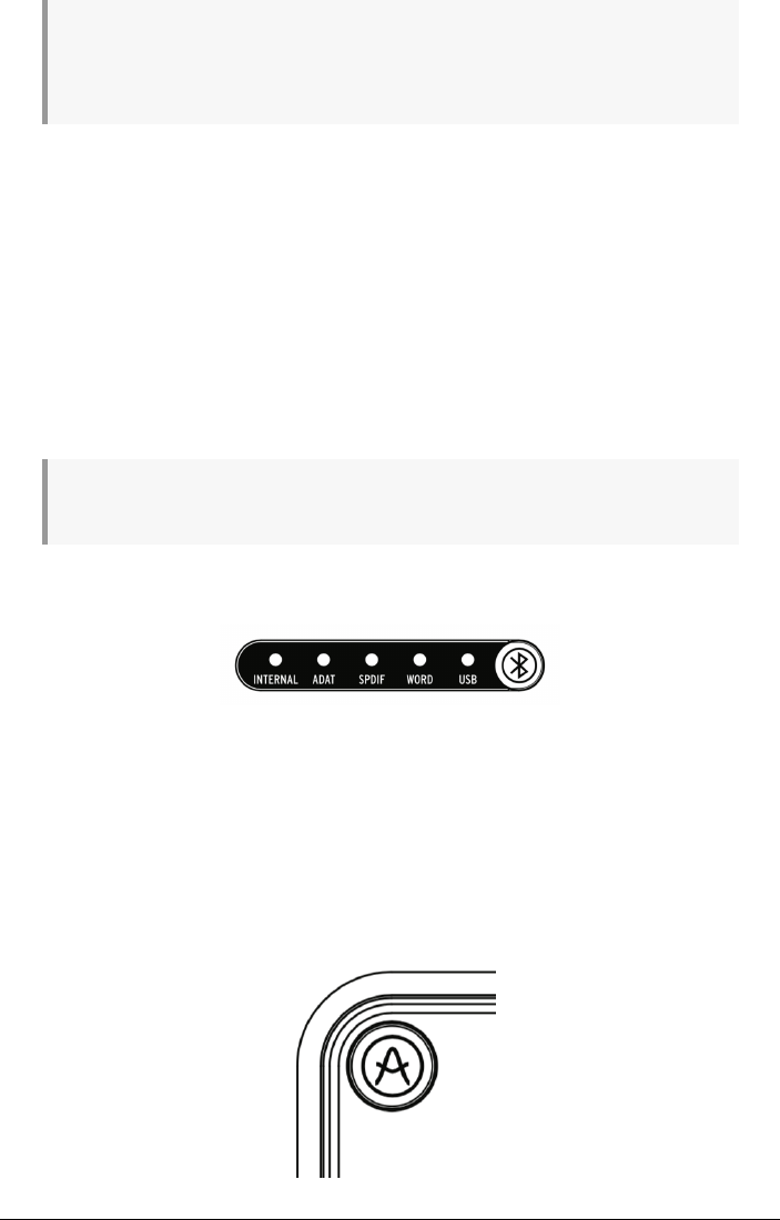
A7. Clock Source and USB Indicators: These LEDs indicate the source of the digital clock
(internal, ADAT, SPDIF or Word Clock) and the status of the USB connection.
The USB LED is illuminated when the connection is OK and blinks if there is either a problem
with the USB connection or there is no USB connection at all to the computer. You can
select the clock source of AudioFuse Studio in the AudioFuse Control Center software under
Settings (Gear Icon) > Audio Settings > Clocks. The selected external clock LED blinks if
lost or incorrect. In this situation, the unit automatically switches to Internal clock at the
same sample rate. Please refer to the AudioFuse Control Center User Manual [p.45] for more
information.
A8. AudioFuse Studio Button: This button opens and closes the AudioFuse Control Center on
your computer.
Arturia - User Manual AudioFuse Studio - AudioFuse Studio 9

It is a handy shortcut to accessing the Control Center application without having to use your
computer's mouse or trackpad.
1.2.2. Front View
B1. Input channels 1-4: Connect microphones, instruments or line-level devices to these four
inputs. The "combo" style connectors accept XLR (microphone) or 1/4” (instrument or line-
level) inputs. Each channel has its own Input Control Section directly above it on the front
panel so you can set things like input gain or monitor incoming levels. See callout A1 above
to learn more about the Input Control Section.
B2. Headphone Outputs: Connect your headphones here. AudioFuse Studio has two
independent headphone ("cue") outputs and each output has both 1/4" and 1/8" connectors
so you never have to worry about losing headphone adapters. The Phones Control Section
directly above these connectors on the front panel lets you set the output level, select the
signal source and set mono/stereo operation. Refer to callout A3 above to learn more about
the Phones Control Section.
♪: The 1/4" and 1/8" headphone outputs have different impedance values so that you can connect
virtually any kind of headphone to AudioFuse Studio. The 1/4" are optimized for high impedance
headphones (30-600 ohm) and have a 13 dBu maximum output level. The 1/8" connectors are optimized
for low impedance headphones (8-120 ohm) and have a 10 dbU maximum output level.
10 Arturia - User Manual AudioFuse Studio - AudioFuse Studio

1.2.3. Back View
C1. Power Section: Connect the supplied DC power adapter here and use the nearby power
button to switch the product on and off. The threaded connector can be locked into place to
avoid accidentally disconnecting the power. To make life easier for international travelers,
the "worldwide" power supply includes interchangeable leads letting you use the product
nearly anywhere in the world without having to buy adapters or power converters.
!: AudioFuse Studio is intended to be used with its supplied DC power supply. While the interface
can be "bus powered" by your computer through the USB-C connector, most of its functionality must
be switched off as USB cannot deliver enough current to power the unit. When bus powered, the
interface works as a dual headphone amplifier with reference grade digital-to-analog conversion. All
other features (USB hub, preamplifiers, speaker outputs, etc.) are switched off. It is important to note
some computer may not have the capability to provide enough power for this "bus powered" mode.
C2. USB-C Connector: Connect AudioFuse Studio to your computer with one of the provided
USB cables. AudioFuse Studio features a USB 2.0 protocol to communicate with your
computer. It can also work with many smartphone and tablets but these devices may
require specialized USB adapters to make the connection. This is detailed in the next chapter
of this guide.
C3. USB hub: AudioFuse includes a handy 3-port USB hub to connect your master keyboard,
USB memory stick or dongle. Two of the ports (labeled "1A") can deliver up to 1 amp of power
for rapid charging of devices. The third port provides up to 120mA of current is intended for
low power devices such a dongle or USB memory stick.
!: We advise only connecting products with low power requirements (such as USB dongles) to the
120mA port. Connecting devices with higher power requirements may trigger an overcurrent protection
mechanism that will temporarily deactivate the 120mA port. If you wish to connect products with more
demanding power requirements, use the 1A ports instead.
C4. Speaker Outputs A&B: Connect up to two pairs of active speakers to these balanced 1/
4” outputs for easy A/B monitoring. The Output Control Section on the top panel lets you do
things like select the active pair of speakers, set output levels, select the sound source of the
speakers and more. See callout A5 above to learn more about the Output Control Section.
C5. Aux (Reamp) Output: These multi-tasking outputs have some special features not
typically found on other interfaces. Firstly, they are DC coupled, letting you control of
modular synths directly from your DAW audio or control voltage (CV) signals. Secondly,
these outputs can change impedance and allow you to send a "dry" recorded guitar or bass
track back out to any amp for rerecording (or "reamping") later. This handy feature opens
up many interesting sound design possibilities and saves you from having to buy costly "DI"
or "reamping" boxes.
Arturia - User Manual AudioFuse Studio - AudioFuse Studio 11

C6. Insert Section: These connectors let you "insert" external line-level devices such as
compressors into the signal path after the AudioFuse Studio's DiscretePro preamplifiers but
before its analog-to-digital converters. To do this, you will need to use TRS "send/return"
cables. If nothing is connected here, the DiscretePro preamp's output is automatically sent
to the digital converter.
C7. Phono/Line inputs 5-8: Connect external phono or line-level devices to these RCA and
balanced 1/4” inputs. The Phono input may not be suitable for high cartridge output levels
(typically above 5-10 mV). The AudioFuse Control Center application lets you configure the
RCA inputs to accept either standard line-level signals (like the output of your smartphone,
for example) or the output of a turntable requiring RIAA-equalization. This is done on the
main screen under the Analog Inputs > Inputs 5-6 section. Please refer to the AudioFuse
Control Center User Manual [p.53] to learn more.
♪: These inputs connect directly to the AudioFuse Studio's pristine analog-to-digital converters (unless
the RIAA filter is switched on inputs 5-6, in which case the signal flows through that filter first). If you
own fancy "outboard" products like a tube preamp or a vocal strip, connect them here avoid double-
amplifying your signals (once through your preamp and again through the DiscretePro preamp). Doing
so will provide the cleanest possible signal path and also leaves the DiscretePro preamplifiers free to
capture other signals.
C8. Grounding Pin: This pin is used in conjunction with the Phono inputs to create a common
ground between a turntable and the AudioFuse Studio. Be sure to always use the grounding
pin when connecting a turntable to help you avoid ground hum loops, buzzes and other
unwanted sounds in your recordings.
C9. Optical Input/Output Section: These connectors can be used to transmit and receive
ADAT and S/PDIF signals over optical cables. ADAT is a multi-channel format that carries
up to 8 channels of audio whereas S/PDIF always carries stereo (2-channel) signals. The
exact functioning of this outut is configured in the AudioFuse Control Center software under
Settings (Gear Icon) > Audio Settings > Digital I/O. Please refer to the AudioFuse Control
Center User Manual [p.45] for more information.
♪: The ADAT standard supports up to 8 channels of audio at sampling rates of 44.1/48k. However,
when working at higher sampling rates (88.2k or 96k) each optical cable can only carry 4 channels
of audio (the format does not support 176.4k or 192k sampling rates). To overcome this limitation,
AudioFuse Studio has two separate input connectors and two separate output connectors, letting you to
transfer 8 channels of ADAT signals even if you are working at 88.2k or 96k sampling rates.
C10. WordClock & S/PDIF Section: These connectors can be used to transmit and receive
coaxial (RCA) S/PDIF signals as well as Word Clock synchronization signals. Use the
AudioFuse Control Center to define how you would like these connectors to operate. Refer
to that application's User Manual [p.45] to learn more.
C11. MIDI In/Out: Connect MIDI devices here using the supplied MIDI Adapters. The MIDI
ports are available in your computer once the AudioFuse drivers are installed (these drivers
are installed along with the AudioFuse Control Center application).
C12. Kensington Lock Port: AudioFuse Studio is portable and easy to carry. However, it
should be carried away only when you want it carried away! We’ve included a Kensington
lock slot on the rear panel so you can secure it to the surface of your choice.
12 Arturia - User Manual AudioFuse Studio - AudioFuse Studio

1.3. Getting started
1.3.1. Powering your AudioFuse Studio
AudioFuse Studio is a professional-grade recording interface and it has higher power
requirements than most consumer products. For this reason, it must be powered using its
included worldwide DC power supply (15V, 3A).
1.3.2. Setting your Operating System
1.3.2.1. Setup on macOS
Connect AudioFuse Studio to your computer's USB Port and switch on the unit. AudioFuse
Studio will appear in the
Audio MIDI Setup
as shown:
To set up AudioFuse Studio to work as your default audio input/output device:
• Select AudioFuse Studio in the Audio MIDI Settings left panel
• Right-click AudioFuse Studio and set it as default input device
• Right-click AudioFuse Studio again and now set it as default output device
Arturia - User Manual AudioFuse Studio - AudioFuse Studio 13

1.3.2.2. Set up on Windows
Low latency drivers on Windows are provided by Arturia and are automatically installed
with the AudioFuse Control Center installer. You can download AudioFuse Control Center
here:
www.arturia.com/audiofuse-start
Once AudioFuse Control Center is installed, simply connect the interface to your computer
using the supplied USB cable and switch on the unit. Windows will detect the hardware and
it will appear under your audio devices.
Open “Manage Audio Device”
Here you can configure AudioFuse Studio to be your default recording device, playback
device or both. To do so, select the interface under the
Playback
and
Recording
tabs and
press the
Set Default
button.
1.3.2.3. Set up on iPad/iPhone
First, connect AudioFuse Studio to its DC adaptor and switch on the unit. Next, connect
AudioFuse Studio to your iOS device through the camera connection kit (required).
AudioFuse Studio will appear under Settings > General > About > AudioFuse. For more
information please refer to www.arturia.com/audiofuse-start
1.3.2.4. Set up on Android
First, connect AudioFuse Studio to its DC adaptor and switch on the unit. Next, connect the
interface to an Android device through an On-The-Go cable. Android 5+ is required. For more
information please refer to www.arturia.com/audiofuse-start
14 Arturia - User Manual AudioFuse Studio - AudioFuse Studio

1.3.3. The AudioFuse Control Center
Our AudioFuse Control Center (AFCC) software lets you to dive deep into the AudioFuse
Studio's features and to manage all the special functions that are not directly accessible
from the top panel. For example you can modify the
Main
,
Cue 1
and
Cue 2
monitor mixes,
modify digital input/output settings, select the digital clock source, update the product's
firmware and much more. In short, AFCC lets you reconfigure the interface so that it works
best for you and your studio. All of AFCC's powerful features are covered in section 2 [p.38]
of this user guide.
Arturia - User Manual AudioFuse Studio - AudioFuse Studio 15
1.4. How to use AudioFuse Studio
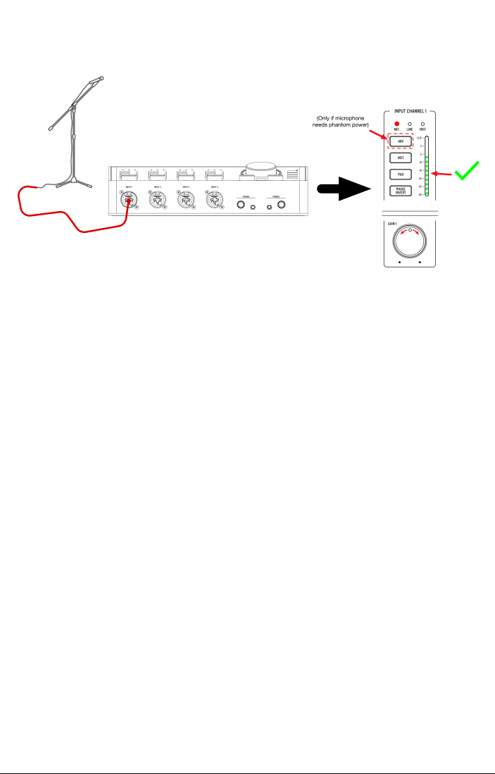
1.4.1. How to record with a microphone
1. Connect your microphone to AudioFuse Studio with an XLR cable. You can use
any input on the front panel.
2. AudioFuse Studio will auto-detect that you have connected an XLR cable and the
Mic LED will light up in the Input Channel section.
3. If your microphone requires phantom power, press the 48V button to switch on
phantom power.
4. Talk or sing into the mic while adjusting the gain knob. The loudest parts of your
performance should cause the channel's VU meter to peak between -10 and
-6dB.
5. If your sound source is so loud that it overloads the VU meter even at the lowest
gain setting, press the Pad button to switch on the 20dB input gain reduction.
Note that the CLIP LED will light up when the input signal reaches 1dB before
distortion.
That's it! The microphone input should be available in your music software and ready to
record. Please refer to your software's user guide if you have any questions about how to
record.
16 Arturia - User Manual AudioFuse Studio - AudioFuse Studio

1.4.2. How to record a synth, guitar or other instrument
1. Connect your synth, guitar or other instrument with a standard 1/4" cable. You
can use any input on the front panel.
2. AudioFuse Studio will auto-detect that you have connected a 1/4" cable and either
the
Line
or
Inst
LED will light up in the Input Channel section.
3. Press the Inst button to ensure that the right kind of input device (line-level or
instrument) is selected:
◦ If you are using a line-level instrument (synthesizers, drum machines
and most studio or hifi equipment) then the "Line" LED should be
illuminated.
◦ If you have connected an electric guitar, bass, or another kind of
instrument with passive pickups then the "Inst" LED should be
illuminated.
4. Play the instrument while adjusting the gain knob. The loudest parts of your
performance should cause the channel's VU meter to peak between -10 and
-6dB. Please note that the Pad is activated by default when a channel is in Line
mode.
5. If your sound source is so loud that it overloads the VU meter even at the lowest
gain setting, press the Pad button to switch on the 20dB input gain reduction.
Please note that the PAD is activated by default in Line mode
You're all set! You should now be able to see your instrument in your music software and be
ready to record. Please refer to your software's user guide if you have any questions about
how to record.
Arturia - User Manual AudioFuse Studio - AudioFuse Studio 17

1.4.3. Inserting external effects into your signal path
It is sometimes very desirable to insert a compressor, equalizer or other effect into your
analog signal path before converting it to digital and sending it into your computer to be
recorded. The Insert connectors on the back of AudioFuse Studio make this easy.
1. Connect your microphone or instrument to AudioFuse Studio by following the
instructions in the two sections above.
2. Use a special TRS to dual-TS "insert" cable to inject your external device into the
signal path. The cable's "send" connector goes to your external device's input.
The "return" connector should be connected to your external device's output and
brings the signal back into AudioFuse Studio.
3. External devices can sometimes shift your loudness levels up or down so you
may need to adjust the device's output to ensure your peaks are still between -10
and -6dB. Use can use the VU meters on AudioFuse Studio to confirm that input
levels are good.
Job done! Your signal is now being routed from the DiscretePro preamp's output through the
external device and back to AudioFuse Studio's pristine analog-to-digital converter.
♪: Here is a Pro Tip: It's possible to send line level signals directly to the converters (and bypass the
DiscretePro preamplifiers) by only using the "return" portion of an insert cable and leaving the "send"
connector unplugged. You can also take the output of DiscretePro preamplifier by only using the "send"
portion of the cable while leaving the "return" portion unplugged. Technically minded engineers may be
interested to know that these inserts send and receive signals at line level (+18 dBu for 0 dBFS).
1.4.3.1. About TRS to Dual-TS Cables
Insert cables are a special category of cables that allow mixers and other devices to send
and receive signals on the same physical connector. This is done through a clever use of a
balanced TRS (tip-ring-sleeve) cable containing three internal wires.
18 Arturia - User Manual AudioFuse Studio - AudioFuse Studio

These cables normally connect one TRS connector to another TRS connector. In this
scenario, a signal is sent "one way" along the cable with the positive and negative polarities
of an identical signal being sent on the "tip" and "ring" and a common ground being provided
on the sleeve.
When using insert cables, the tip of the cable is instead used to "send" the signal to an
external device whereas the middle "ring" is used to bring signal back. The third "sleeve" is
used to provide a common ground as it normally is used.
Arturia - User Manual AudioFuse Studio - AudioFuse Studio 19

1.4.4. Re-Amping
AudioFuse has a great Re-amping function that opens up many creative options when
mixing. Re-amping is sometimes called "reverse D.I." and is when you play a dry (sometimes
called "direct" or "D.I.") recorded guitar or bass track back out to an amplifier to record
the result. This lets you play the exact same guitar or bass performance through several
different amplifiers (or the same amplifier set to different settings) and capture the
amplified sounds as usual with microphones. Having the ability to re-record the same
performance through different amplifiers lets you create really interesting mixes such as:
• Mixing low frequency growl of one amp with the high frequency sparkle of
another for the perfect guitar tone
• Hearing two different amps panned left and right but playing an
identical
performance
• Re-recording a great performance through a different amp long after the session
has ended
!: Note that it is not possible to simply play a standard line-level signal into an amplifier since
amplifiers expect to see a high-impedance (Hi-Z) instrument level signal. Playing a regular line-level
signal will generate sub-optimal results due to the impedance and level mismatch between what is
played and what is expected at the amp. To re-amp properly, the proper reverse DI circuitry must be in
place like with AudioFuse Studio.
To do this:
1. Make a "direct" recording of a guitar or bass in your music software. This is done
by plugging the instrument directly into one of the AudioFuse Studio's front panel
inputs (this process is described earlier in this chapter).
2. Set the Aux outputs of AudioFuse Studio to function as re-amping outputs. This
can be done through the AudioFuse Control Center application. Refer to that
software's User Manual [p.59] to learn how to do this.
3. Connect the re-amping outputs to your amplifier.
4. Playback the direct recording to the amplifier while recording the output of the
amplifier with a microphone (this is described earlier in this chapter).
20 Arturia - User Manual AudioFuse Studio - AudioFuse Studio

1.4.5. Use one headphone for Cue, and one for Main
Since AudioFuse Studio has two independent headphone outputs, you can monitor two
separate mixes at the same time. For example, the producer or engineer can hear the main
mix while a vocalist can listen to a special mix designed to help them sing at their best.
1. Use the Cue Select buttons to select the Main mix on headphone output 1 and Cue
1 (or Cue 2) on headphone output 2.
2. Use the Headphone Level knobs to adjust the volume for each set of headphones.
3. The Main, Cue 1 and Cue 2 mixes can be modified using the AudioFuse Control
Center application. Please refer to that software's User Manual to learn how to do
this.
Arturia - User Manual AudioFuse Studio - AudioFuse Studio 21

1.4.6. Use AudioFuse to switch between 2 sets of active speakers
It is common practice for recording engineers to audition their mixes on different speakers
as they work. For example, they may have professional studio monitors as their main
speakers but a pair of cheap hi-fi speakers as a "reality check" to ensure that the mix is
sounding good even on lower quality speakers. Other engineers may have professional
studio monitors as their main speakers but a massive PA speaker system for visiting clients
that like to hear it turned up loud.
The Speaker A and Speaker B outputs on AudioFuse Studio make doing this very easy.
1. Connect your main speakers to Speaker Output A
2. Connect your second set of speakers to Speaker Output B
3. Press the Speaker Selector button to switch between your two pairs of speakers.
♪: The AudioFuse Control Center application includes a trim knob that lets you precisely match
loudness levels between your A and B speakers. Please refer to the AudioFuse control Center User
Manual [p.45] to learn how to do this.
22 Arturia - User Manual AudioFuse Studio - AudioFuse Studio

1.4.7. Connect to AudioFuse Studio with Bluetooth
AudioFuse Studio has a built in Bluetooth receiver enabling a best in class Bluetooth audio
experience. This is very useful because it allows users to wirelessly connect smartphones,
tablets and computers with AudioFuse Studio and to stream music through the studio's
speakers or to simply record the Bluetooth signal into your music software. Since AudioFuse
Studio is a standalone device, the studio computer does not even need to be switched on to
do this!
!: Please note that only SBC, AAC, MP3 and aptx formats are supported by the AudioFuse Studio
Bluetooth receiver. Other formats are not supported.
1: Press the Bluetooth button on the top panel of AudioFuse Studio. It is illuminated in blue
when Bluetooth is active.
2: Connect to AudioFuse Studio from your smartphone, tablet or other device.
♪: The interface appears as "AF_STUDIO" followed by the serial number of your product. If you are
not sure how to connect to a Bluetooth device, refer to your product's user guide.
3: Start playing music.
You may need to configure your phone, tablet or other device to stream its output to the Bluetooth
device instead of playing it from the built-in speaker. Again, please refer to your products user guide to
learn how to do this.
Arturia - User Manual AudioFuse Studio - AudioFuse Studio 23

1.4.8. Use AudioFuse Studio without a computer
AudioFuse Studio is a standalone product, meaning it can work without a computer as a
mixer and monitor controller. To do this:
1. Connect your analog and digital devices to the inputs of AudioFuse Studio.
2. Connect the AudioFuse outputs to your speakers.
3. Connect the AudioFuse to the computer.
4. Launch AudioFuse Control Center and create up to three mixes (Main, Cue 1 and
Cue 2) from the inputs.
Now you can unplug the computer and the AudioFuse Studio hardware will continue to
mix your inputs even if a computer is no longer present. Your mix settings are saved in
AudioFuse Studio so even if you switch off the interface, the settings will be remembered
next time you restart the unit. All speaker and headphone related features (volume control,
source select, mute, dim and mono modes) also continue to work, meaning there is quite a
lot of functionality at your fingertips even if the computer is no longer present.
1.4.9. Using Phones 2 to Control Speaker B
AudioFuse Studio has the ability to route the second headphone output signal to the Speaker
B output. Since the signal being routed is sourced after the headphone volume control knob,
it means that you can use the second headphone's "Level" knob to control the loudness level
of speaker B. This gives you independent volume control of Speaker Output A (via the Master
Volume knob) and Speaker Output B (via the Phones 2 Level knob) thus having both speaker
outputs A & B playing audio simultaneously with Phones 2 volume controlling the Speaker
B's output level.
This option can be set in the AudioFuse Control Center. Please refer to that software's User
Manual [p.45] to learn how to do this.
1.4.10. Loopback Mode
AudioFuse Studio includes two additional "loopback" input channels (USB channels 17-18) that
are not accessed through the front or rear panels of the interface. They are connected to
a dedicated USB record stream, so the output of any application on your computer can be
"looped back" and recorded directly into your music software. This saves you from having to
physically connect the outputs (the outputs of your application) to a pair of available inputs
that your music software can then record.
1.4.11. Talkback on ADAT 1-2
AudioFuse Studio's Talkback microphone can be routed to its Speaker, Phones 1, Phones 2,
ADAT Output 1-2 or any combination of these outputs through the AudioFuse Control Center
application. Routing Talkback to ADAT 1-2 enables sending talkback to an external ADAT
expander unit such as the AudioFuse 8Pre. In this case, if the AudioFuse 8Pre ADAT input
1-2 is routed to its headphone output, then the talkback is heard on headphone output of
AudioFuse 8Pre. This can be very useful in scenarios where the AudioFuse 8Pre is set up in
another room in the studio.
24 Arturia - User Manual AudioFuse Studio - AudioFuse Studio

1.4.12. SPDIF Out from Speaker
By default, AudioFuse Studio's SPDIF output carries its own signal and is independent of the
other outputs. However, AudioFuse Studio has the ability to set its SPDIF output to mirror
the main speaker output after the master volume control knob. This is an extremely useful
feature if you are using an external digital to analog converter or certain speakers that
have SPDIF inputs. This can be set in the AudioFuse Control Center application. Refer to that
product's documentation [p.45] to learn more.
1.4.13. AUX outputs from Inputs 1-4 (and DAW)
It is possible to route a variety of sources to the AUX outputs of AudioFuse Studio: Main mix,
Cue 1, Cue 2, the direct output of your DAW and the direct input on channels 1-4. This is very
useful as it allows you to record a live guitar "direct" through the AudioFuse instrument input
while simultaneously sending the live analog signal off to a guitar amplifier that you can
also record separately. This is something that can normally be done only with a costly DI
box with a splitter.
Having the ability to do this means you can capture the sound of the guitar amp "as played"
but also have a backup DI recording available in case you decide that you would like a
different guitar tone. In this case, you can re-amp the DI recording using the instructions
described earlier in this chapter.
Arturia - User Manual AudioFuse Studio - AudioFuse Studio 25

1.5. An in-depth look at AudioFuse Studio
This chapter covers the inner workings of AudioFuse Studio. While the knowledge contained
in this chapter is not strictly necessary for everyday use, we think technically minded users
may find it interesting!
1.5.1. Input Paths in Detail
1.5.1.1. Input Channels 1 - 4
The functional block diagram above shows the complete input signal path of the four Input
Channels of AudioFuse Studio. Notice that DiscretePro preamplifiers actually consist of two
separate preamplifiers!
• The XLR input path is designed specifically to handle microphone signals with
the highest fidelity.
• The 1/4" input path is similarly designed to handle Line and Instrument-level
signals with the highest possible fidelity. This path is sub-divided into two
different paths, one for standard line-level and the other for "hi-z" instrument level
inputs (the
Inst
button on the front panel determines which path is selected).
• Each input path (Mic and Instrument) has its own dedicated Pad, and--as
mentioned before--there are two separate high-end preamplifiers for each path
to ensure the highest possibly fidelity for each source.
The amplified signal is then sent through the (optional) phase-reversal circuit and send on
to the insert jack. If nothing is connected to the insert jack, the signal is automatically sent
on to the analog-to-digital converter. If you do connect a device like a compressor or EQ to
the insert jack, then the signal is "sent" to that device and "returned" to the analog-to-digital
converter. You can learn how to do this in Chapter 4.
Finally, notice that VU metering happens after the analog-to-digital conversion. This ensures
that you are monitoring the actual digital signal that is being sent to the computer. If there
is any digital clipping taking place, you will be sure to see it here.
26 Arturia - User Manual AudioFuse Studio - AudioFuse Studio

1.5.1.2. Inputs 5 - 6
Inputs 5-6 on AudioFuse Studio can be used to bring in line-level signals (like from external
synthesizers or external preamplifiers) or phono signals (turntables) through RIAA
amplifiers specifically designed for turntables.
!: You cannot use the Line and Phono inputs simultaneously.
Notice that these inputs (Line and Phono) have separate signal paths optimized for each
kind of signal. You can select the active signal path through the AudioFuse Control Center
application. Note that the line-level inputs have an optional 20 dB padding circuit that can
be switched on and off through the AudioFuse Control Center application. Refer to that
software's documentation [p.53] to learn more.
Arturia - User Manual AudioFuse Studio - AudioFuse Studio 27

1.5.1.3. Inputs 7 - 8
Inputs 7-8 can bring in line-level signals (just like channels 5-6 above) but can also bring in
signals via AudioFuse Studio's Bluetooth receiver and the built-in talkback microphone. The
AudioFuse Control Center application lets you set a variety of parameters including:
• The routing of the Bluetooth signal
• The optional 20 dB padding circuit for the line-level inputs
• The routing of the Talkback microphone
Refer to the AudioFuse Control Center User Manual [p.53] to learn more.
28 Arturia - User Manual AudioFuse Studio - AudioFuse Studio

1.5.1.4. Digital inputs
AudioFuse Studio provides up to 8 digital inputs through the ADAT protocol and another 2
digital inputs from S/PDIF.
The S/PDIF protocol comes in two varieties: Optical and Coaxial (RCA). AudioFuse Studio
supports both variants and you can select which one you would like to use in the AudioFuse
Control Center application. Please refer to that software's User Manual [p.29] to learn more.
Digital Synchronization Possibilities
AudioFuse Studio can synchronize itself to external digital clock sources through many of
the digital inputs on the back panel. This way, the interface can derive a clock source and
drive its internal audio converters according to that source.
The table above lists incoming digital audio ports in columns along the top and the various
methods of synchronization horizontally in rows. The word "Supported" is listed wherever it
is possible to derive an external synchronization signal for AudioFuse Studio to use.
Notice that the synchronization signal does not necessarily have to be part of the incoming
digital audio signal. For example, you can use the coaxial SPDIF connector to receive a
master clock source while the actual audio signals come in through the ADAT 1 and 2 inputs.
This kind of flexibility can be very handy in professional environments with many digital
devices requiring a complex synchronization scheme.
!: When the synchronization signal is not part of the incoming digital audio signal, it is strongly
recommended to make sure the external devices are synced to the same synchronization source.
Arturia - User Manual AudioFuse Studio - AudioFuse Studio 29

• The SPDIF (optical) and ADAT 2 inputs share the same optical port on the back
panel of AudioFuse Studio. You can determine whether this port acts as a SPDIF
or ADAT connector using the Audio Fuse Control Center application. Please refer
to the AFCC User Manual [p.45] to learn how to do this. Note that this port cannot
be used to synchronize ADAT signals (only ADAT 1 can transfer ADAT clock).
1.5.2. Monitor Mixing and Routing
AudioFuse Studio offers three powerful low latency "monitor mixers" inside itself called:
Main
,
Cue 1
and
Cue 2
. These three stereo mixers can be freely dialed in and routed to the
speakers (
Speaker A
or
Speaker B
) or headphones (
Cue 1
or
Cue 2
) to provide a near-zero
latency mix.
1.5.3. Creating a Monitor Mix
The
Main
,
Cue 1
and
Cue 2
mixes are created using the AudioFuse Control Center software.
They can be created using any of the analog or digital inputs of AudioFuse Studio as well
as up to six "software return" outputs of your music software. Please refer to the AudioFuse
Control Center User Manual [p.55] to learn how to create or modify monitor mixes.
1.5.4. Routing Monitor Mixes to speakers and headphones
Once you have created a monitor mix, you have a great deal of flexibility in routing that mix
to various destinations. For example, you can listen to the
Main Mix
on your speakers while
two different vocalists receive their own custom mix (
Cue 1
and
Cue 2
) in their headphones.
If desired, you can quickly switch the source of the speakers to Cue 1 or Cue 2 to hear
what your vocalists are hearing and then switch back. This is done using the Source Select
buttons on the top panel of AudioFuse Studio. The Source Select buttons and other top panel
controls are covered in Chapter 2 of this guide.
30 Arturia - User Manual AudioFuse Studio - AudioFuse Studio

1.5.5. USB Audio mapping
AudioFuse Studio displays differing numbers of input and output channels in your music
software depending on your selected sampling rate.
Sampling Rate Inputs Outputs
44.1 / 48 kHz 20 18
88.2 / 96 kHz 18 18
176.4 / 192 kHz 10 10
The tables below contain detailed information about inputs and outputs at each sampling
rate.
1.5.5.1. Audio Mapping at 44.1 / 48 kHz sampling rates:
Input Computer Input (REC) Computer Output (Playback)
1 Input Channel 1 Main Left
2 Input Channel 2 Main Right
3 Input Channel 3 Cue 1 Left
4 Input Channel 4 Cue 1 Right
5 Line Input 5 / Phono (Input 5) Cue 2 Left
6 Line Input 6 / Phono (Input 6) Cue 2 Right
7 Line Input 7 Aux Out Left
8 Line Input 8 / Talkback Aux Out Right
9 S/PDIF Left S/PDIF Left
10 S/PDIF Right S/PDIF Right
11 ADAT 1 ADAT 1
12 ADAT 2 ADAT 2
13 ADAT 3 ADAT 3
14 ADAT 4 ADAT 4
15 ADAT 5 ADAT 5
16 ADAT 6 ADAT 6
17 ADAT 7 ADAT 7
18 ADAT 8 ADAT 8
19 Loopback Left -
20 Loopback Right -
Arturia - User Manual AudioFuse Studio - AudioFuse Studio 31

1.5.5.2. Audio Mapping at 88.2 / 96 kHz sampling rates:
Input Computer Input (REC) Computer Output (Playback)
1 Input Channel 1 Main Left
2 Input Channel 2 Main Right
3 Input Channel 3 Cue 1 Left
4 Input Channel 4 Cue 1 Right
5 Line Input 5 / Phono (Input 5) Cue 2 Left
6 Line Input 6 / Phono (Input 6) Cue 2 Right
7 Line Input 7 Aux Out Left
8 Line Input 8 / Talkback Aux Out Right
9 S/PDIF Left S/PDIF Left
10 S/PDIF Right S/PDIF Right
11 ADAT 1 ADAT 1
12 ADAT 2 ADAT 2
13 ADAT 3 ADAT 3
14 ADAT 4 ADAT 4
15 ADAT 5 ADAT 5
16 ADAT 6 ADAT 6
17 ADAT 7 ADAT 7
18 ADAT 8 ADAT 8
1.5.5.3. Audio Mapping at 176.4 / 192 kHz sampling rates:
Input Computer Input (REC) Computer Output (Playback)
1 Input Channel 1 Main Left
2 Input Channel 2 Main Right
3 Input Channel 3 Cue 1 Left
4 Input Channel 4 Cue 1 Right
5 Line Input 5 / Phono (Input 5) Cue 2 Left
6 Line Input 6 / Phono (Input 6) Cue 2 Right
7 Line Input 7 Aux Out Left
8 Line Input 8 Aux Out Right
9 S/PDIF Left S/PDIF Left
10 S/PDIF Right S/PDIF Right
32 Arturia - User Manual AudioFuse Studio - AudioFuse Studio

1.5.6. Clock Synchronization
Digital audio devices need to be synchronized to one master clock in order to exchange
audio data properly. AudioFuse Studio can run on its own internal clock or it can synchronize
itself to external clock sources.
The (default) internal clock of AudioFuse Studio is extremely stable and will offer you the
best performance in most situations. If you have the option to drive your peripheral gear
from AudioFuse Studio's internal clock, please do so. However, if you do need to have
another device to function as the master clock and to have AudioFuse Studio synchronize
itself to that device's clock, you can do so through the AudioFuse Control Center software.
Please refer to the AudioFuse Control Center User Manual [p.45] to learn how to do this.
1.5.6.1. Using the Internal Clock
The internal clock of the AudioFuse can operate at the following sampling rates:
• 44.1 kHz
• 48 kHz
• 88.2 kHz
• 96 kHz
• 176.4 kHz
• 192 kHz
The sampling rate can be set from AudioFuse Control Center, your computer's audio control
panel or your music software depending of the computer's operating system.
If the AudioFuse Studio is set to use its internal clock, it can function as a master clock
for other external devices. When using its internal clock source, AudioFuse Studio will
automatically deliver digital master clock over its outputs depending on how you have
configured the digital IO settings: - If Word Clock is selected: The interface delivers Word
Clock on coax, and ADAT clock on ADAT 1 - If SPDIF and Coax are selected: The interface
SPDIF clock on coax out, and ADAT clock on ADAT 1 - If SPDIF and Optical are selected: The
interface only delivers SPDIF clock on ADAT 2 connector
When AudioFuse Studio is synchronized to an external clock source, it still can deliver digital
audio clock as shown:
• Sync on Word Clock : deliver ADAT & Word Clock
• Sync SPDIF coax : deliver SPDIF & ADAT clock
• Sync SPDIF optical : deliver only SPDIF opt clock
• Sync ADAT : Deliver ADAT clock & Spdif or Word depending of Word/SPDIF
selection
Arturia - User Manual AudioFuse Studio - AudioFuse Studio 33

1.5.6.2. Using External Clock Sources
If you must use an external device to function as the master clock, you can set AudioFuse
Studio to synchronize itself to that device. AudioFuse Studio is quite flexible and can
synchronize to signals coming from any of its digital inputs:
• Word Clock - using the
WCLK | S/PDIF
RCA input on the rear panel
!: When using the Word Clock input and synchronizing AudioFuse Studio to external sources, you will
need to "terminate" the input if AudioFuse Studio is the last device in your chain. The AudioFuse Studio
hardware supports this and you can switch on 75 OHM termination from the Audio Fuse Control Center
application. Note that when using AudioFuse Studio as the word clock
master
, you do not need to set
the Word Clock Termination parameter. Please refer to the "Digital Coax Termination" [p.45] section of
the AFCC User Manual to learn how to do this.
• S/PDIF Coax – using the
WCLK | S/PDIF
RCA input on the rear panel
• S/PDIF Optical – using the SPDIF (ADAT 5-8) optical connector
• ADAT – using the ADAT 1-8 (1-4) optical connector
!: The maximum supported sample rate for ADAT clocking is 96kHz.
34 Arturia - User Manual AudioFuse Studio - AudioFuse Studio

1.6. Specifications
• 18 inputs, 20 outputs channels
• 4 mic/instrument/line preamps with DiscretePRO® technology
• 4 additional line inputs, with inputs 5-6 commutable to Phono
• 4 analog inserts on channel 1-4
• Bluetooth stereo audio receiver supporting aptX© and AAC©
• 2 pairs of speaker analog outputs on balanced TRS Jack
• 2 independent stereo headphones outputs, on both 6.35 and 3.5mm TRS.
• 2 independent analog line outputs with reamp capability (instrument impedance
output)
• Complete monitoring section with individual level control for speakers and
phones
• Direct monitoring ultra-low latency internal mixers
• 8 digital ADAT inputs/outputs up to 96kHz
• S/PDIF inputs/outputs or Word clock input, output/thru on Cinch RCA
• Integrated Talkback feature with a dedicated built-in microphone
• MIDI In & Out
• 3-port USB hub (with two 1A ports for rapid charging)
• DiscretePRO® Individual audio performance certificate delivered with each unit.
• 24-bit latest generation AD/DA converters at up to 192kHz sampling rate.
• USB-C interface compatible with PC & Mac, fully USB 2.0 compatible
• Comes with AudioFuse Creative Suite
• Robust metal desktop chassis
Line Inputs
Input Impedance 20kΩ (symmetric), 10kΩ (asymmetric)
Maximum Input Level +24dBu
Gain Range 45dB typical
Pad Mode -20dB
Frequency Response 20Hz/20kHz +/-0.01dB typical
Dynamic Range 119dB (A-weighted)
THD+N -112dB (A-weighted)
Instrument Inputs
Input Impedance 1.1MΩ (asymmetric)
Maximum Input Level +18dBu
Gain Range 45dB typical
Pad Mode -20dB
Frequency Response 20Hz/20kHz +/-0.01dB typical
Dynamic Range 119dB (A-weighted)
THD+N -112dB (A-weighted)
Arturia - User Manual AudioFuse Studio - AudioFuse Studio 35

Line Aux Inputs
Input Impedance 20kΩ (symmetric), 10kΩ (asymmetric)
Maximum Input Level +24dBu
Pad Mode -20dB
Frequency Response 20Hz/20kHz +/-0.02dB typical
Dynamic Range 120dB (A-weighted)
THD+N -108dB (A-weighted)
Microphone Preamps
Input impedance 3.4kΩ
Maximum input level +11dBu
Gain range 71dB typical
Boost mode +10dB
Pad mode -20dB
Frequency response 20Hz to 20kHz +/-0.09dB
Equivalent Input Noise (EIN) -129dB typical (un-weighted)
THD+N @ 1kHz -107dB (A-weighted)
Dynamic range 118dB (A-weighted)
Input Inserts
Output Impedance 240Ω balanced, 120Ω unbalanced
Input Impedance 20kΩ (balanced), 10kΩ (unbalanced)
Aux / Line / Speaker Outputs
Output Impedance 240Ω balanced, 120Ω unbalanced
Maximum Output Level +24dBu
Dynamic Range 121dB (A-weighted)
THD+N -108dB (A-weighted)
Frequency response 20-20kHz +/-0.07dB
36 Arturia - User Manual AudioFuse Studio - AudioFuse Studio

Phones Outputs
Output Impedance
10Ω on 6.35mm TRS
33Ω on 3.5mm TRS
Maximum Output Level
+13dBu on 6.35mm TRS
+10dBu on 3.5mm TRS
Dynamic Range 103dB (A-weighted)
THD+N @ 1kHz -92dB (A-weighted)
Power @ 33ohm @1%THD
60mW on 6.35mm TRS
22mW on 3.5mm TRS
Talkback Microphone
Max input Level (@440Hz) 95dB SPL
Dynamic range 55dB
Audio bandwidth 120Hz - 8kHz
Clocks
Supported Frequency Rates 44.1 kHz, 48 kHz, 88.2 kHz, 96 kHz, 176.4 kHz, 192 kHz
Arturia - User Manual AudioFuse Studio - AudioFuse Studio 37

2. AUDIOFUSE CONTROL CENTER
2.1. Welcome to AudioFuse Control Center!
Arturia has a long history of developing highly sought-after hardware products, while also
crafting supplementary software that enhances the capabilities of the hardware many
times over.
The AudioFuse Control Center (AFCC) is software that was specifically designed to
complement the already impressive series of AudioFuse interfaces. It provides access to
features that are not available directly on the physical units, in addition to the features that
are. The AFCC runs on Windows and macOS systems.
These feature-packed devices, combined with the power and flexibility of the AudioFuse
Control Center, will help you capture and control any musical magic that you can imagine.
Features of AudioFuse Control Center
• Control most of the front-panel features of your AudioFuse device remotely
• Configure hidden parameters such as Digital Coax Termination and other device-
specific features
• Visual representation of signal routing, input/output levels, channel status, etc.
• View device settings such as sample rate, sync lock
• Quick selection between multiple AudioFuse devices
• Notifies you of firmware upgrades
• Window size can be optimized for your display monitor
• Runs on Windows and macOS systems
2.2. Overview
2.2.1. The Main window
In keeping with the "everything you need at your fingertips" design of the AudioFuse series,
there is one main window for the AudioFuse Control Center (AFCC). Other than the basic
setup options found in the Menu bar, everything the selected unit can do is right before your
eyes; there are no additional menus or alternate pages. And if you have more than one unit
attached to your computer you can switch back and forth between them easily.
2.2.1.1. Two-way communication
You'll love the way your AudioFuse device interacts with its Control Center software: when
you push a button on the unit, the equivalent control inside the AFCC will do the same
thing. The buttons work both ways: they light up when pressed on the unit or clicked in the
software.
Most of the physical knobs are analog controls, so they do not have an equivalent control
in the AFCC. The only exceptions are the big Output Level knobs on the AudioFuse and
AudioFuse Studio; when those are moved, the value changes in the AFCC and the equivalent
control will move in the AFCC. (For the AudioFuse it's the big Output Level knob; for the
AudioFuse Studio it's the Speakers fader in the Analog Outputs section). The physical knob
won't move when the AFCC control is moved, though.
38 Arturia - User Manual AudioFuse Studio - AudioFuse Control Center

2.2.1.2. Basic operations
It's obvious how to use some features, like pushing a button, selecting a menu, or moving
a knob or slider. But there are some other great features and operational tips we should
mention as you are beginning to learn to use the AFCC.
Tool tips
The AFCC window displays values of the controls as they are being edited. You can also
hover over a control with the cursor if you'd like to see its current value before you edit it.
A quick description of the functions and controls can also be displayed in the bottom status
bar of the AFCC.
Reset Parameters to Default
We've made it easy to return a parameter to its default value, such as re-centering the
pan value for a channel, etc. To do this, either double-click the related control or use a
combination of Option + Click (macOS) or Alt + Click (Windows).
Fine adjustments (0.1 dB increments)
Some parameters have a very wide range, such as the level faders or the pan knobs. You
can move these controls quickly to get close to the value you want, and then fine-tune the
value by doing the following:
• macOS: Right click + drag the cursor, or hold Ctrl + drag the cursor.
• Windows: Right click + drag the cursor, or hold Ctrl + drag the cursor.
Arturia - User Manual AudioFuse Studio - AudioFuse Control Center 39

2.2.2. The AudioFuse Studio window
This window has three main sub-sections. You'll always see the same basic items in the
top and bottom sections. The middle window is the one that can change its appearance the
most, depending on the Monitor mix you want to have available. It also can be hidden and
revealed as needed to help maximize your screen space.
Section Name Function
1
Input
zone [p.53]
Displays input types, button options, and LED level meters
2
Monitoring
Mix [p.55]
Shows Cue Mix components, controls levels, pan, and solo/mute status, and allows
adding, removing, naming and grouping of channels
3
Output
zone [p.59]
Displays input/output assignments, allows editing of input assignments, provides
source selection for Loopback feature, and has LED level meters
2.2.2.1. AudioFuse Studio controls not in AFCC
Most of the AudioFuse Studio buttons are linked to a button in the AFCC, except for the Listen
and Talkback buttons. As the physical button is pressed the virtual button will toggle, either
in the Analog Inputs section or the Analog Outputs section.
The following AudioFuse Studio controls are analog and do not communicate their actions
to the computer. As a result they have no equivalent control in the AFCC:
The AudioFuse Control Center interface
40 Arturia - User Manual AudioFuse Studio - AudioFuse Control Center

Control Function
Gain 1-4 Use the physical knobs to set the level for the analog input channels.
Listen Press to isolate the selected signal at the selected output. Routing options are set in the AFCC.
Phones Provides level control for the selected headphone output.
Talkback Press the button to activate the built-in microphone. Routing options are set in the AFCC.
♪: The Listen and Talkback buttons are not part of the AFCC main window, but their behavior can be
defined inside the Audio Settings tab of the Device Settings window [p.45].
Arturia - User Manual AudioFuse Studio - AudioFuse Control Center 41

2.3. The Menu bar
The strip along the top of the AudioFuse Control Center is called the Menu bar. Its contents
may vary depending on which device you have selected.
2.3.1. The Arturia menu
Click the upper left-hand corner of the AFCC window to open the Arturia menu.
2.3.1.1. Resize Window
The AFCC automatically detects the size of your monitor and selects the optimal
magnification value. But you can override this setting and it will be remembered the next
time you launch the AFCC.
42 Arturia - User Manual AudioFuse Studio - AudioFuse Control Center

2.3.1.2. AFCC Manual
The AFCC has a built-in Help file (this manual). To open it, select the word "Manual" from the
drop-down menu.
2.3.1.3. About
This menu item provides information about the AudioFuse Control Center. It lists the
engineering credits and displays the current version of the software you have installed.
Arturia - User Manual AudioFuse Studio - AudioFuse Control Center 43

2.3.2. Device Selection
This window allows you to select between devices when more than one AudioFuse product
is connected to the same computer. That way you can choose which one you want to
modify with the AFCC.
2.3.3. Device Status
The Menu bar has two fields that show you the status of the AudioFuse Studio at a glance.
• Sample Rate displays the sample rate being generated or received.
• Clock Source indicates the sync selection: Internal, WORD, or ADAT Clock.
To change these settings, navigate to Device Settings > Audio Settings.
44 Arturia - User Manual AudioFuse Studio - AudioFuse Control Center

2.3.4. Device Settings
Click the gear-shaped icon in the upper right corner of the Menu bar to open the Device
Settings window. It has three tabs which contain the audio settings, preferences, and
firmware update information for the AudioFuse Studio.
2.3.4.1. Audio Settings
The Audio Settings tab is where the basic operational settings for the AudioFuse Studio are
located. We'll describe each one in the following paragraphs.
Digital I/O
The AudioFuse Studio rear panel offers several ways to send and receive digital audio. This
AFCC window determines how the unit will handle SPDIF data. Two parameters are shown:
Arturia - User Manual AudioFuse Studio - AudioFuse Control Center 45

• SPDIF Type options are Coaxial and Optical. The Coaxial setting sends and
receives SPDIF data at the WCLK | S/PDIF In/Out RCA connectors. The Optical
setting sends and receives SPDIF data at the Optical In/Out S/PDIF ports (also
labeled ADAT 5-8).
• Digital Coax Format Selection options are SPDIF and Word. SPDIF sends and
receives SPDIF data at the WCLK | S/PDIF In/Out RCA connectors. The Word
setting means that the WCLK | S/PDIF connectors will send and receive Word
clock signals only.
♪: The Digital Coax Format Selection is not accessible when the SPDIF Type is set to Optical.
The following chart presents this information in another way that may be helpful.
[1] = Specified format can be received if incoming sample rate matches the Clock Source
selection [2] = ADAT audio can be sent at a sample rate that matches the Clock Source
selection n/a = not available or not applicable
Clocks
46 Arturia - User Manual AudioFuse Studio - AudioFuse Control Center

Clock Source
This field determines whether the AudioFuse Studio operates according to its internal clock
or synchronizes to an external clock source. There are four options: Internal, ADAT, S/PDIF,
or Word Clock.
A small Lock icon indicates if the unit's clock is locked to the desired clock source. If Orange,
the desired clock source is invalid.
Sample Rate
If the Clock Source of the AudioFuse Studio is set to Internal, you can use this field to select
the Sample Rate at which the unit will operate. If the Clock Source is set to one of the
external source options, this field is greyed out and cannot be altered here. The sample rate
that is shown will match the sample rate of the master device.
♪: In macOS the Sample Rate can be changed using Audio MIDI Setup or within your DAW project.
Digital Coax Termination
If the AudioFuse Studio will be the Word Clock master for your system then you don't need
to set the Digital Coax Termination parameter. But if you plan to slave the unit to Word Clock,
then this parameter is important.
There are two settings for the Digital Coax Termination parameter: 75 Ohm and Hi-Z. Which
one to use depends on whether the unit is last in the Word Clock chain or somewhere in the
middle. In case the AudioFuse Studio is the last device in the WordClock chain, please set
the Input Impedance parameter to 75 Ohms to terminate the clock chain. If another unit is
connected to the AudioFuse Studio WordClock output, please select HiZ.
Listen Button
Each of the first four input channels on the AudioFuse Studio has a Listen button. This AFCC
window determines how they respond when pressed.
• Mode options are PFL (Pre-fader level) and Solo. PFL allows you to hear the
direct signal coming into the input, regardless of the fader setting in the AFCC
Monitoring Mix section. Solo activates the Solo button for that channel in the
Monitoring Mix and sets the level according the Monitoring Mix fader. The signal
for that input will be heard when the Listen button is pressed.
• Routing offers three destinations for the audio depending of the selected Mode.
!: Be careful! If any live microphones are in the same room with the speakers when the SPK option
is selected, you could experience LOUD feedback through your speakers as the soloed signal is picked
up by the mics, routed through the speakers, picked up by the mics again, etc.
Arturia - User Manual AudioFuse Studio - AudioFuse Control Center 47

Ground Lift
This parameter could be handy when using the Re-Amp feature. If you hear a ground hum
when the AudioFuse Studio is connected to a guitar amplifier, try setting the Aux Out Ground
Lift parameter to On.
♪: The Ground Lift is only activated when one or both of the Aux Out Re-Amp circuits is activated,
even when this parameter is set to On. In other words, if the Re-Amp feature is not being used, the
Ground Lift will not be activated.
Speakers
Speakers A/B Volume
It is possible to link the output levels of Speaker A and Speaker B. If you prefer not to have
them linked, choose the Independent setting.
Speakers A/B Trim Level
Some monitor speakers may have input characteristics that cause them to clip the audio
sooner than other monitor speakers do. Conversely, some monitor speakers may be able to
withstand a hotter input. This allows you to offset their output levels to compensate for this,
using the Speakers A level as a reference point and then applying the offset to the Speakers
B level.
The value can be altered in a positive or negative direction; just click and drag the knob up
or down until the proper ratio is achieved. The range is -12 dB to + 12 dB.
Hold the Control key and click/drag for more precise control of this parameter. Double-click
the knob to reset the value to 0 dB.
Speakers Dim Level
This menu sets the amount of level reduction that occurs at all stereo outputs when the Dim
button is pressed. The Dim level is also applied when the Talkback feature is engaged.
48 Arturia - User Manual AudioFuse Studio - AudioFuse Control Center

Talkback
The Talkback button activates the built-in microphone of the AudioFuse Studio. This AFCC
window determines how the Talkback audio is processed.
• Mode The Talkback feature shares the same input as line input 8, so the AFCC
offers two Modes that let you specify what the Talkback feature can do when
something is plugged into input 8.
◦ Auto: if something is plugged into input 8, then the Talkback feature
can not be activated
◦ Force: the Talkback feature can be activated even if something is
plugged into input 8.
• Use the Level knob to adjust the level of the built-in Talkback microphone.
• The Routing button allows you to route the Talkback output to the Speakers (SPK),
Phones 1, Phones 2, or ADAT outputs 1 and 2. All four can be active if you like. The
ADAT 1-2 button provides an added benefit, in that it routes the Talkback audio
to an ADAT-equipped device such as the AudioFuse 8Pre. The AudioFuse 8Pre
then routes the Talkback audio to its headphone outputs, further integrating your
studio and enhancing your productivity.
!: Be careful! If any live microphones are in the same room with the speakers when the SPK option
is selected, you could experience LOUD feedback through your speakers as the soloed signal is picked
up by the mics, routed through the speakers, picked up by the mics again, etc.
Bluetooth
This parameter determines what happens to the incoming audio after the AudioFuse Studio
has been paired with a Bluetooth device:
• Exclusive: this setting routes the Bluetooth channels to all monitoring outputs
(Speaker and Phones). With this setting only the Bluetooth audio will be heard on
the monitoring outputs.
• Input Channels 7/8: the Bluetooth signal is handled the same as any other stereo
pair of input channels. The channels are hard-panned to the left and right.
Arturia - User Manual AudioFuse Studio - AudioFuse Control Center 49

Setting this parameter to Input Channels 7/8 makes it possible to route audio from a
Bluetooth device to a stereo channel in your DAW. Recordings or tracks you've made on your
mobile device can now become part of your session and part of your song.
2.3.4.2. Preferences
The ASIO settings are described below; please refer to the following sections for information
about Clipping Reset, Peak Meter Reference Level, Peak Meter Orange Color Threshold and
Device Name.
Clipping Reset
You can select the amount of time it will take for the AFCC Clip LEDs to reset after they have
been triggered. There are four options:
• None: the LEDs will reset immediately.
• Infinite: the LEDs will stay lit indefinitely unless reset manually using the AFCC.
• 1.5 sec: the LEDs will stay lit for a brief moment (1.5 seconds) and then reset.
• 3 sec: the LEDs will stay lit for a bit longer (3 seconds) and then reset.
The Peak Meter Reference Level
The Peak Meter Reference Level is a simple way to indicate the reference level used in the
studio (i.e., the "working level", which is usually -18dBFS for a 1kHz sine). This is a quick,
easy way to check your levels against this calibration, and you can choose the preferred
calibration level within a range of -12 dBFS to -20 dBFS.
The Peak Meter Orange Color Threshold
This parameter sets the lowest level at which the first orange LED will activate for the Input
Channel meters and the Output Level meters.
Device Name
Click in this field to personalize the name of your AudioFuse.
50 Arturia - User Manual AudioFuse Studio - AudioFuse Control Center

Windows: ASIO Settings
♪: The Preferences window for macOS does not have the ASIO Settings options.
These two parameters have a significant impact on the integrity of the audio that passes
through the AudioFuse Studio.
• Buffer Size: The Arturia USB Audio driver automatically selects the optimal buffer
size each time the sample rate changes. You can select a different value, but the
AFCC won't allow a buffer size that is not compatible with the current sample
rate. A warning message will inform you of incompatible settings.
• Safe Mode: Set Safe Mode to On to ensure the integrity of the audio samples.
However, this also places a higher load on the CPU. If you disable this feature,
latency will decrease slightly but the risk of dropped samples will increase.
Disabling Safe Mode is not recommended, unless you work on a particularly
powerful PC with only a few tracks.
Arturia - User Manual AudioFuse Studio - AudioFuse Control Center 51

2.3.5. Firmware Updates
The AFCC will let you know when a new version of the firmware for your device becomes
available. This is the page you will use for the update process. Once the file has been
downloaded to your computer, click "Upgrade from File" to navigate to the file location. Select
the file with the proper extension (.bin for AudioFuse, .afstudio for the AudioFuse Studio,
.af8pre for the AudioFuse 8Pre) and follow the instructions.
When updating the firmware for any AudioFuse device, the unit must be powered by both
connectors (USB and DC).
!: CAUTION: During the firmware update process the AudioFuse device will reboot two times. It is
highly recommended to turn the volume on your monitors down all the way to prevent damage to your
speakers.
During the upgrade process you will be shown a progress bar that indicates how far along
in the process the unit is.
The firmware upgrade in progress
You'll know the upgrade is complete when the progress bar is replaced with the word
"Success":
52 Arturia - User Manual AudioFuse Studio - AudioFuse Control Center

2.4. The Main Window
Beneath its deceptively simple exterior, the AudioFuse Studio provides an astounding array
of features. The AudioFuse Control Center is the key to unlocking their full potential.
2.4.1. Input zone
Spanning the width of the AFCC window beneath the Menu bar is the Input zone. It provides
a visual summary of the analog signals being fed into the AudioFuse Studio, along with
meters that display the signals that are arriving at the ADAT and SPDIF inputs.
2.4.1.1. Analog Inputs
In the expanded view this section shows the status and signal levels of the analog
connectors on the front and rear panels of the AudioFuse Studio. It has:
• buttons that match those on input channels 1-4, which can toggle (and be toggled
by) their physical counterparts
• buttons and knobs that link and control the levels of inputs 5-8, and menus that
specify the connection type
• LED meters that display the signal level of each input
• icons that represent the type of input device being used.
The icon for an unused input channel looks like one of the combo jacks on the AudioFuse
Studio. When you plug something in, the icons change to match the type of connection that
has been made.
For example, plug in an XLR connector and the icon becomes a microphone on a stand;
make a 1/4" connection and the icon becomes a 1/4" plug. When the INST button is activated
for inputs 1-14, the 1/4" plug icon becomes a guitar.
You'll notice that some buttons are greyed out when you use certain types of inputs. For
example, when you plug in a 1/4" cable the AudioFuse Studio knows you will not need
phantom power for that device, so the 48V button is deactivated.
The following table lists the buttons that can be used with each input type.
Analog input # Button name Visible for input type: Possible settings
1-4 48V Microphone On (lit red), Off
1-4 PAD
Microphone
Line, Instrument
Off, PAD (-20dB), BOOST (+10dB)
Off, PAD (-20dB)
1-4 INST Line, Instrument On (lit blue), Off
1-4 PHASE Microphone, Line, Instrument On (lit blue), Off
5-8 LINK Line RCA, Phono On (lit blue), Off
7-8 PAD Line, Instrument Off, PAD (-20dB)
Arturia - User Manual AudioFuse Studio - AudioFuse Control Center 53

♪: The icons do not change when an insert connection is used for input channels 1-4.
Inputs 5-8: Menu options
Input pairs 5-6 and 7-8 have drop-down menus that specify the type of device that is
connected.
For Inputs 5-6 the options are Line TRS, Line RCA, and Phono. Connect a device to the 1/4"
jacks or the RCA jacks (not both) and then select one of the following:
• Line TRS: Use this with a balanced or unbalanced line-level input such as a
keyboard, drum machine, etc.
• Line RCA: Use this with a consumer line-level input such as a the output of a CD
player, etc. (-10dBV).
• Phono is for use with a turntable. Be sure to use the GND connector on the
rear panel of the AudioFuse Studio when connecting a turntable. See the
documentation for those devices to determine the optimal connection method.
For Inputs 7-8 the choices are TRS Line or Bluetooth.
• TRS Line: Use this setting to connect a line-level input such as a keyboard, drum
machine, etc.
• Bluetooth: Use this when pairing the AudioFuse Studio with a Bluetooth device.
♪: If you're using a pre-amp for your instrument, such as the output of an effects unit, you may be
able to use the Line setting instead.
2.4.1.2. Digital Inputs
This section only has LED level meters. They display the signal levels for each of the
incoming ADAT tracks and the SPDIF input. There are no other functions available; what
they get is what you see. When no valid incoming digital signals are detected, the Digital
Inputs label and icon are greyed.
54 Arturia - User Manual AudioFuse Studio - AudioFuse Control Center

2.4.2. Monitoring Mix zone
Section Name Function
1 Channel display Adjust level, pan, Solo / Mute status of Monitoring Mix channels
2 Master level fader & meter Adjust overall level of selected Mix, numerical readout of peak levels
3 Mix selection tabs Select Main Mix, Cue Mix 1, or Cue Mix 2
4 Add / Remove Tracks Define contents of selected Mix
5 Copy Mix Click to copy selected Mix, then select the target Mix tab
6 Group Tracks Link specific Mix channels for simultaneous edits
At the center of the AFCC window is the Monitoring Mix zone. Its function is to define the
Monitoring Mixes: Main Mix, Cue Mix 1, and Cue Mix 2. Any one of these mixes can be
adjusted independently and sent to any of the unit's outputs.
Each of the six sub-sections will be described in order.
2.4.2.1. The Channel display
This section occupies the majority of the Monitoring Mix zone. Which channels you will see
here depends on what you want the selected Monitoring Mix to contain. For example, it might
have only a few Analog inputs, a half-dozen ADAT tracks, and one or more sources arriving
over USB from your DAW. You can make these selections using the Add / Remove Tracks
feature [p.56].
Use the individual faders of each mono or stereo input channel to set their levels. This will
affect the selected Monitoring Mix only, not what is sent to the DAW input channels.
Naming Channels
To name a channel, click in the name field below the channel fader and type the desired
name. If no name is entered the default name for that channel will be used: Analog 1-2, ADAT
3, USB 5-6, etc.
Arturia - User Manual AudioFuse Studio - AudioFuse Control Center 55

2.4.2.2. The Master level fader
Just like the master fader on a physical mixing console controls the combined output of all
of the audio passing through the console, the Master level fader of the AFCC allows you to
raise or lower the combined output of all of the input channels in the Channel display before
it is sent to the selected output. As with the individual channel levels in the Channel display,
the Master fader will affect the selected Monitoring Mix only, not what is sent to the DAW
input channels.
Master peak value
The small window above the fader shows the peak levels that occur during playback.
Double-click the value field to reset it.
Mix Selection tabs
There are three tabs on the upper-right side of the Master fader section labeled Main Mix,
Cue Mix 1, and Cue Mix 2. Each of these tabs selects an independent mixer, each with its own
selection of input channels and controls (level, pan, solo and mute). This makes it possible
to provide one mix to the monitor speakers, for example, and separate mixes to each of the
headphones. Once a mix is constructed it can be routed to any output (Speakers, Aux Out,
or either set of headphones).
Beneath the Mix Selection tabs are three sections that will help you assemble each mix
quickly and make the most of them all.
Add or Remove Tracks
The Add / Remove Tracks section defines which channels will be included in the selected
mix. To open the Input Selection window, click the + / - button.
56 Arturia - User Manual AudioFuse Studio - AudioFuse Control Center

This shows all of the input sources that can be included in the selected mix. You can select
individual sources by clicking on a number, or select stereo sources by clicking one of the
buttons that contains two numbers. As each button is clicked a channel will be added or
removed to the Channel display in the Monitoring Mix section, which remains visible in the
background.
Note that input sources that are not included in the mix will not be heard in the mix.
Channel display access slider
When a large number of input sources are added to the mix a slider appears along the
bottom of the Monitoring Mix window, allowing you to access the input sources that have
been pushed out of view.
Another method is to resize the AFCC window by click/dragging the triangle in the lower
right corner. This will allow you to see all of the channels in the Monitoring Mix at the same
time, depending on the number of included channels and the size of your monitor.
Copy Mix
The selected mix might be a good starting point for constructing one of the other mixes.
This feature lets you copy one mix to another, after which you can make any needed
adjustments to levels, inputs, etc. Here's the process:
1. Select the source Mix (Main, Cue Mix 1, Cue Mix 2). For this example we’ll select
the Main Mix.
2. Click the Copy Mix button
3. Select the destination Mix by clicking its tab (Cue Mix 1 or Cue Mix 2).
4. After the selection has been confirmed, the source Mix will be copied onto the
destination Mix.
Grouping Tracks
This function lets you create and select different Track Groups within the selected mix, so
you can adjust them all with a single action. Grouped tracks can be muted or soloed with a
single click, for example, or you can adjust their levels by moving a single control.
There are four color-coded groups available for each mix. When a channel is added to a
group, the name field under that channel's fader is highlighted with that same color.
To select a Track Group, click one of the four buttons. Once a group is selected you can
adjust its settings as described above, or you can edit the group or clear it.
Edit the Track Group
Follow these steps to assign or remove individual channels from a Track Group.
Arturia - User Manual AudioFuse Studio - AudioFuse Control Center 57

1. Click the Edit button.
2. Select the Track Group you want to edit by clicking its button.
3. Click the name field for the channel you want to assign or remove from the Track
Group.
4. If you want to edit the contents of a different Track Group, simply select another
Track Group button. Then follow the same steps to assign or remove the channels
from that Track Group.
5. When you are done, click the Edit button to exit this mode.
Clear the Track Group
If you want to remove all of the channels from a Track Group and start over, it's easy to do:
• Click the Clear button.
• Select the Track Group you want to clear by clicking its button.
All channels will be removed from the Track Group immediately.
♪: If a grouped track is removed from the mixer, it is no longer part of this group.
♪: alt+click allow to change a parameter of a grouped track without affecting the group.
58 Arturia - User Manual AudioFuse Studio - AudioFuse Control Center

2.4.3. Output zone
Stretching across the bottom of the AFCC window from left to right is the Output zone. It
shows at a glance the signals that are passing through the AudioFuse Studio, along with the
sources and levels as indicated by the LED meters. Each output has a drop-down menu that
allows you to select which input source will be routed to which output.
Note that not all outputs are stereo pairs: The Aux L / R outputs are the exception. They can
be routed and controlled independently or linked and controlled as a stereo pair. More about
that later.
2.4.3.1. Analog Outputs
The source for each set of Analog Outputs can be selected. For example, there are three
options for the Speakers: Main Mix, Cue Mix 1, and Cue Mix 2.
The following table lists all of the input / output routing options that are available in the
selection menu for each analog output.
Speakers Phones 1 Phones 2 Aux L Aux R
Main Mix Main Mix Main Mix Main L Main Mix R
Cue Mix 1 Cue Mix 1 Cue Mix 1 Cue Mix 1 L Cue Mix 1 R
Cue Mix 2 Cue Mix 2 Cue Mix 2 Cue Mix 2 L Cue Mix 2 R
USB [1] USB [1]
Analog Inputs 1-4 Analog Inputs 1-4
[1] The USB inputs for the Aux channels are the ones routed to them via the DAW or another
computer source.
The Analog Output buttons
There are 10 buttons in the Analog Outputs section. They make the AudioFuse Studio even
more flexible and powerful!
Mute
This button silences all of the Speaker outputs. Click it again to unmute.
Mono
There's a Mono button available for three of the Analog Outputs. when this button is pressed
the stereo output becomes mono. Use this to check your mix every now and then to make
sure your listeners will not encounter any phase cancellation issues if they listen to your
song through a single speaker.
Dim
Arturia - User Manual AudioFuse Studio - AudioFuse Control Center 59

Clicking this button reduces the output level of the Speakers by an amount defined within
the AudioFuse Studio Preferences window [p.50]. Click it again to restore the level to its
original setting. See Audio Settings: AudioFuse Studio [p.45] in the Menu bar chapter [p.42] for
more information.
Spk B
Two sets of monitor speakers can be connected to the AudioFuse Studio, and this button lets
you switch between them for the selected output (Speakers or Phones 2). On the physical
unit the Output Level knob controls the level for the Speakers, and the second Phones knob
controls the level for Phones 2. The Master faders in the Monitoring Mix section can also
control the levels, depending on the selected source for the specific Analog Output.
Remember, there are two configuration options available in the Audio Settings window that
can be used to link and offset the speaker levels.
Re-Amp
This button activates the Re-Amping feature for that Aux output (Left or Right. You can use
both if needed). This causes the Aux output to switch its impedance to match the input on
a guitar amplifier, enabling you to route a "clean" guitar recording into the guitar amp and
re-record its output.
Link
This button toggles the state of the Aux L and Aux R outputs between linked and unlinked.
When linked they become a stereo pair, with a shared source and level. When unlinked their
sources and levels can be different.
2.4.3.2. Digital Outputs
The source for each pair of Digital Outputs can be selected. For example, there are four
options for digital outputs 1-2: Cue Mix, USB In 1-2, or Analog In 1-2.
This table lists all of the input / output routing options that are available in the selection menu
for each digital output.
ADAT Out 1-2 ADAT Out 3-4 ADAT Out 5-6 ADAT Out 7-8 S/PDIF Loopback
Main Mix Main Mix Main Mix Main Mix Main Mix Main Mix
Cue Mix 1 Cue Mix 1 Cue Mix 1 Cue Mix 1 Cue Mix 1 Cue Mix 1
Cue Mix 2 Cue Mix 2 Cue Mix 2 Cue Mix 2 Cue Mix 2 Cue Mix 2
USB [1] USB [1] USB [1] USB [1] USB [1] Disabled
Speaker
ADAT IN 1-2 ADAT IN 3-4 ADAT IN 5-6 ADAT IN 7-8 SPDIF IN 1-2
[1] The USB input channels for these outputs are the ones routed to them via the DAW or
another computer source.
60 Arturia - User Manual AudioFuse Studio - AudioFuse Control Center

2.4.3.3. Loopback section
The Loopback section provides two additional recording input channels that are not
accessed through the front or rear panels of the AudioFuse Studio: USB channels 19 and 20.
They are connected to a dedicated USB record stream, so the output of another application
or of one of the AudioFuse studio monitoring mixer can be recorded directly by a DAW.
The source for the Loopback channels can be the Main Mix, Cue Mix 1, or Cue Mix 2 of the
AudioFuse Studio. There is also a Disabled selection if this function is not required.
♪: The Loopback section is only available when the sample rate is set to 44.1 kHz or 48 kHz.
Arturia - User Manual AudioFuse Studio - AudioFuse Control Center 61

3. SOFTWARE LICENSE AGREEMENT
In consideration of payment of the Licensee fee, which is a portion of the price you paid,
Arturia, as Licensor, grants to you (hereinafter termed “Licensee”) a nonexclusive right to
use this copy of the SOFTWARE.
All intellectual property rights in the software belong to Arturia SA (hereinafter: “Arturia”).
Arturia permits you only to copy, download, install and use the software in accordance with
the terms and conditions of this Agreement.
The product contains product activation for protection against unlawful copying. The OEM
software can be used only following registration.
Internet access is required for the activation process. The terms and conditions for use of the
software by you, the end-user, appear below. By installing the software on your computer
you agree to these terms and conditions. Please read the following text carefully in its
entirety. If you do not approve these terms and conditions, you must not install this software.
In this event give the product back to where you have purchased it (including all written
material, the complete undamaged packing as well as the enclosed hardware) immediately
but at the latest within 30 days in return for a refund of the purchase price.
1. Software Ownership Arturia shall retain full and complete title to the SOFTWARE recorded
on the enclosed disks and all subsequent copies of the SOFTWARE, regardless of the media
or form on or in which the original disks or copies may exist. The License is not a sale of the
original SOFTWARE.
2. Grant of License Arturia grants you a non-exclusive license for the use of the software
according to the terms and conditions of this Agreement. You may not lease, loan or sub-
license the software. The use of the software within a network is illegal where there is the
possibility of a contemporaneous multiple use of the program.
You are entitled to prepare a backup copy of the software which will not be used for
purposes other than storage purposes.
You shall have no further right or interest to use the software other than the limited rights as
specified in this Agreement. Arturia reserves all rights not expressly granted.
3. Activation of the Software Arturia may use a compulsory activation of the software and
a compulsory registration of the OEM software for license control to protect the software
against unlawful copying. If you do not accept the terms and conditions of this Agreement,
the software will not work.
In such a case the product including the software may only be returned within 30 days
following acquisition of the product. Upon return a claim according to § 11 shall not apply.
4. Support, Upgrades and Updates after Product Registration You can only receive support,
upgrades and updates following the personal product registration. Support is provided only
for the current version and for the previous version during one year after publication of the
new version. Arturia can modify and partly or completely adjust the nature of the support
(hotline, forum on the website etc.), upgrades and updates at any time.
The product registration is possible during the activation process or at any time later through
the Internet. In such a process you are asked to agree to the storage and use of your
personal data (name, address, contact, email-address, and license data) for the purposes
specified above. Arturia may also forward these data to engaged third parties, in particular
distributors, for support purposes and for the verification of the upgrade or update right.
5. No Unbundling The software usually contains a variety of different files which in its
configuration ensure the complete functionality of the software. The software may be used
as one product only. It is not required that you use or install all components of the software.
You must not arrange components of the software in a new way and develop a modified
version of the software or a new product as a result. The configuration of the software may
not be modified for the purpose of distribution, assignment or resale.
62 Arturia - User Manual AudioFuse Studio - Software License Agreement

6. Assignment of Rights You may assign all your rights to use the software to another
person subject to the conditions that (a) you assign to this other person (i) this Agreement
and (ii) the software or hardware provided with the software, packed or preinstalled
thereon, including all copies, upgrades, updates, backup copies and previous versions,
which granted a right to an update or upgrade on this software, (b) you do not retain
upgrades, updates, backup copies und previous versions of this software and (c) the
recipient accepts the terms and conditions of this Agreement as well as other regulations
pursuant to which you acquired a valid software license.
A return of the product due to a failure to accept the terms and conditions of this Agreement,
e.g. the product activation, shall not be possible following the assignment of rights.
7. Upgrades and Updates You must have a valid license for the previous or more inferior
version of the software in order to be allowed to use an upgrade or update for the software.
Upon transferring this previous or more inferior version of the software to third parties the
right to use the upgrade or update of the software shall expire.
The acquisition of an upgrade or update does not in itself confer any right to use the
software.
The right of support for the previous or inferior version of the software expires upon the
installation of an upgrade or update.
8. Limited Warranty Arturia warrants that the disks on which the software is furnished is
free from defects in materials and workmanship under normal use for a period of thirty (30)
days from the date of purchase. Your receipt shall be evidence of the date of purchase. Any
implied warranties on the software are limited to thirty (30) days from the date of purchase.
Some states do not allow limitations on duration of an implied warranty, so the above
limitation may not apply to you. All programs and accompanying materials are provided “as
is” without warranty of any kind. The complete risk as to the quality and performance of the
programs is with you. Should the program prove defective, you assume the entire cost of all
necessary servicing, repair or correction.
9. Remedies Arturia's entire liability and your exclusive remedy shall be at Arturia's option
either (a) return of the purchase price or (b) replacement of the disk that does not meet the
Limited Warranty and which is returned to Arturia with a copy of your receipt. This limited
Warranty is void if failure of the software has resulted from accident, abuse, modification,
or misapplication. Any replacement software will be warranted for the remainder of the
original warranty period or thirty (30) days, whichever is longer.
10. No other Warranties The above warranties are in lieu of all other warranties, expressed
or implied, including but not limited to, the implied warranties of merchantability and fitness
for a particular purpose. No oral or written information or advice given by Arturia, its dealers,
distributors, agents or employees shall create a warranty or in any way increase the scope
of this limited warranty.
11. No Liability for Consequential Damages Neither Arturia nor anyone else involved in
the creation, production, or delivery of this product shall be liable for any direct, indirect,
consequential, or incidental damages arising out of the use of, or inability to use this product
(including without limitation, damages for loss of business profits, business interruption, loss
of business information and the like) even if Arturia was previously advised of the possibility
of such damages. Some states do not allow limitations on the length of an implied warranty
or the exclusion or limitation of incidental or consequential damages, so the above limitation
or exclusions may not apply to you. This warranty gives you specific legal rights, and you
may also have other rights which vary from state to state.
Arturia - User Manual AudioFuse Studio - Software License Agreement 63

4. DECLARATION OF CONFORMITY
USA
Important notice: DO NOT MODIFY THE UNIT!
This product, when installed as indicate in the instructions contained in this manual, meets
FCC requirement. Modifications not expressly approved by Arturia may avoid your authority,
granted by the FCC, to use the product.
IMPORTANT:
When connecting this product to accessories and/or another product, use only
high quality shielded cables. Cable (s) supplied with this product MUST be used. Follow all
installation instructions. Failure to follow instructions could void your FCC authorization to
use this product in the USA.
NOTE:
This product has been tested and found to comply with the limit for a Class B
Digital device, pursuant to Part 15 of the FCC rules. These limits are designed to provide
a reasonable protection against harmful interference in a residential environment. This
equipment generate, use and radiate radio frequency energy and, if not installed and used
according to the instructions found in the users manual, may cause interferences harmful
to the operation to other electronic devices. Compliance with FCC regulations does not
guarantee that interferences will not occur in all the installations. If this product is found to
be the source of interferences, witch can be determined by turning the unit “OFF” and “ON”,
please try to eliminate the problem by using one of the following measures:
• Relocate either this product or the device that is affected by the interference.
• Use power outlets that are on different branch (circuit breaker or fuse) circuits or
install AC line filter(s).
• In the case of radio or TV interferences, relocate/ reorient the antenna. If the
antenna lead-in is 300 ohm ribbon lead, change the lead-in to coaxial cable.
• If these corrective measures do not bring any satisfied results, please the local
retailer authorized to distribute this type of product. If you cannot locate the
appropriate retailer, please contact Arturia.
The above statements apply ONLY to those products distributed in the USA.
CANADA
NOTICE:
This class B digital apparatus meets all the requirements of the Canadian
Interference-Causing Equipment Regulation.
AVIS
: Cet appareil numérique de la classe B respecte toutes les exigences du Règlement sur
le matériel brouilleur du Canada.
This product complies with the requirements of European Directive 89/336/EEC
This product may not work correctly by the influence of electro-static discharge; if it
happens, simply restart the product.
64 Arturia - User Manual AudioFuse Studio - Declaration of Conformity
