You must read the Usage and Safety Precautions before use.
© 2022 ZOOM CORPORATION
Copying or reprinting this manual in part or in whole without permission is prohibited.
Product names, registered trademarks and company names in this document are the property of their respective companies. All trademarks and regis-
tered trademarks in this document are for identification purposes only and are not intended to infringe on the copyrights of their respective owners.
Proper display is not possible on grayscale devices.
Operation Manual

Notes about this Operation Manual
You might need this manual in the future. Always keep it in a place where
you can access it easily. The contents of this document and the specica-
tions of the product could be changed without notice.
◎
Windows® is a trademark or registered trademark of Microsoft® Cor-
poration.
◎
Mac, macOS, iPad, iPhone and iPod touch are trademarks or registered
trademarks of Apple Inc.
◎
The SD, SDHC and SDXC logos are trademarks.
◎
The Bluetooth® word mark and logo are registered trademarks of Blue-
tooth® SIG, Inc. and these marks are used under license by Zoom Cor-
poration.
◎
Other product names, registered trademarks and company names in
this document are the property of their respective companies.
Note: All trademarks and registered trademarks in this document are for
identication purposes only and are not intended to infringe on the
copyrights of their respective owners.
Recording from copyrighted sources, including CDs, records, tapes, live
performances, video works and broadcasts, without permission of the
copyright holder for any purpose other than personal use is prohibited by
law. Zoom Corporation will not assume any responsibility related to in-
fringements of copyrights.
02

Introduction
Thank you very much for purchasing a ZOOM multitrack eld recorder.
The
provides the following features in a compact form.
●
Record the quietest and loudest sounds at high quality with
32-bit oat WAV format
The high-quality analog input circuits can handle signals ranging from the
most delicate to a professional maximum level of +24 dBu.
In addition to 16/24-bit WAV recording, 32-bit oat WAV recording, which
does not require input level adjustment, is also supported.
With 32-bit float WAV format, the recording resolution can be retained
even when changing levels greatly after recording.
●
Simultaneously record 6 channels and 14 tracks
Up to 14 tracks can be recorded simultaneously, including 16/24-bit WAV
and 32-bit float WAV for Inputs 1–6 along with left and right tracks of a
stereo mix.
●
Support for three types of batteries
A USB mobile battery, L battery or AA batteries can be used for power.
●
Two remote control options
Wireless control is possible by installing a ZOOM wireless adapter (e.g.
BTA-1) and using the F6 Control iOS app.
Moreover by connecting an F6 Control, which is a mixer-style controller
designed especially for F Series recorders, with a USB cable, 60mm track
faders, LED level meters and various transport buttons can be used for in-
tuitive sound control. Combined with the F6 Control iOS app, iPhones and
iPads can also be used as large meters with excellent visibility.
●
Support for SMPTE timecode input and output along with
wireless timecode input
The uses a high-precision oscillator that enables it to independently
generate accurate timecode with a discrepancy of less than 0.5 frames
per 24 hours.
If a BTA-1 dedicated wireless adapter is installed, wireless timecode can
be received from a Timecode Systems UltraSync BLUE and written to re-
corded les.
●
Headphone jack with 100mW+100mW maximum output
Clear headphone monitoring is possible using the digital boost function
while sending audio signals to a video camera or other device from the
LINE OUT jack.
●
Flexible signal routing also makes mixer use possible
Pre-fader and post-fader signals from inputs 1–6 can be routed to outputs
freely.
●
Phantom power supply (+24 V or +48 V)
This can be set for each input separately.
●
USB audio interface use with up to 6 ins and 4 outs possible
Use as a 2-in/2-out or 6-in/4-out audio interface (driver required for Win-
dows).
●
Output multitrack audio by USB while recording
While recording to the installed SD card, multitrack audio can be sent to
and from a computer by USB with up to 8 inputs (6 inputs + L/R stereo
mix) and 4 outputs.
This enables simultaneous backup recording and Internet live streaming.
●
360º audio
Ambisonic mode enables 360º spatial audio recording using VR mics. De-
coding from Ambisonic format A to format B is supported along with gain
and setting link functions.
03

04
Achieving high audio quality throughout recording and editing
With the dual A/D converter circuits and support for 32-bit oat WAV les, the can maintain the highest audio quality from recording to post-pro-
duction.
Recording
Dual A/D converter circuit enables recording both loud
and quiet sounds without making gain adjustments
32-bit float WAV file format maintains audio
quality from recording when editing
Post-production

05
For each input circuit, the
has two A/D converters with different input gains. This design enables high-quality audio recording without the need to
adjust gain settings, a step that is normally indispensable.
Providing amazing dynamic range
By combining two A/D converters, a wide dynamic range not possible
with a single A/D converter has been realized.
Switching between two A/D converters
The constantly monitors data from the two A/D converters, and au-
tomatically selects the one that provides the best recording results.
High-gain
A/D converter
Low-gain
A/D converter
Dual A/D converter
A/D converter
switches in
response to
input level
• Airplane
• Nearby thunder
• Train passing on tracks overhead
• Inside train
• Shouting
• Grand piano
• Noisy street
• Chimes
• Ordinary conversation
• Whispering
• Quiet library
• Late night in suburb
Adjust input gain
according to desired
recording volume
Wide dynamic range covered
by two A/D converters
Conventional product
Low noise because
high-gain A/D
converter selected
Low noise because
high-gain A/D
converter selected
No clipping because
low-gain A/D
converter selected
Dual A/D converter circuit overview

06
Resolution advantage
32-bit oat WAV les have the advantage of being able to maintain high
resolution even at low volumes. As a result, quiet sounds can be made
louder when editing after recording without degrading their quality.
16/24-bit linear WAV
32-bit float WAV
Resolution high
Resolution low
Volume raised
Volume raised
32-bit oat WAV les have the following advantages over conventional 16/24-bit linear WAV les.
These features enable the quality of the sound during recording to be maintained even during post-production.
32-bit oat WAV le overview
Clipping advantage
If a waveform sounds clipped when output from the or in a DAW,
it can be edited after recording to lower its volume and restore an un-
clipped waveform because the data in the 32-bit oat WAV le itself is
not clipped.
Still clipped
Saved in data
Not clipped
Clipped recording
Volume lowered
Volume lowered
32-bit float
16/24-bit linear

Contents
Notes about this Operation Manual .........................................................................02
Introduction ....................................................................................................................03
Achieving high audio quality throughout recording and editing .......................04
Dual A/D converter circuit overview ................................................................................... 05
32-bit oat WAV le overview .............................................................................................. 06
Contents .........................................................................................................................07
Names of parts ............................................................................................................. 09
Connecting mics/other devices to Inputs 1–6 .....................................................11
Equipment connection examples .......................................................................................12
Display overview ........................................................................................................... 13
Preparations ..................................................................................................................16
Supplying power ..................................................................................................................... 16
Loading SD cards ................................................................................................................... 18
Turning the power on and off .............................................................................................. 19
Setting the language .............................................................................................................. 20
Setting the date and time ..................................................................................................... 21
Setting the power supply used ............................................................................................ 23
Recording .......................................................................................................................25
Recording process ................................................................................................................. 25
Setting the recording le format ......................................................................................... 26
Selecting inputs and adjusting levels ................................................................................. 27
Recording .................................................................................................................................29
Setting the sampling rate...................................................................................................... 30
Setting the recording mode (bit depth) .............................................................................. 32
Setting MP3 le bit rate (MP3) ............................................................................................ 34
Setting the LR Track ...............................................................................................................36
Capturing audio before recording starts ........................................................................... 38
Setting the recording time display ...................................................................................... 39
Setting the playback time display .......................................................................................41
Folder and le structure ........................................................................................................ 43
Move the previously recorded take to the FALSE TAKE folder. ..................................... 45
Recorded take settings ...............................................................................................46
Changing the note for the next take recorded .................................................................. 46
Setting and managing recorded scene names ................................................................ 48
Changing the track name of the next take recorded (Track Name) ............................. 51
Changing the number of the next take recorded ............................................................. 53
Playback .........................................................................................................................54
Playing recordings .................................................................................................................. 54
Mixing takes ............................................................................................................................55
Monitoring the playback signals of specic tracks during playback ........................... 57
Changing the repeat playback setting ................................................................................ 59
Take and folder operations ........................................................................................60
Working with takes and folders ........................................................................................... 60
Overview of metadata (take information) stored in les ................................................ 66
Checking and editing take metadata ..................................................................................67
Writing a sound report ........................................................................................................... 76
Input settings .................................................................................................................79
Adjusting the input signal monitoring balance ................................................................. 79
Monitoring the input signals of specied tracks .............................................................. 80
Setting the input source ........................................................................................................81
Setting the monitoring volume on the PFL screen ..........................................................83
Cutting low-frequency noise ................................................................................................85
Input limiter ............................................................................................................................. 87
Inverting the input phase ...................................................................................................... 93
Changing the phantom power settings ............................................................................. 95
Applying delay to input signals ............................................................................................ 97
Linking inputs as a stereo pair .............................................................................................99
Adjusting multiple track input levels together ................................................................101
Changing the automatic mixing setting ...........................................................................102
Setting the Ambisonic format ............................................................................................104
Setting the mic position used for Ambisonic recording ...............................................107
07
08
Output settings ...........................................................................................................109
Setting signals sent to the headphone output ...............................................................109
Outputting alerts through headphones ............................................................................112
Setting the headphone output volume curve ..................................................................113
Boosting headphone output to alleviate interference from recorded sound............114
Setting the output level .......................................................................................................116
Applying delay to the output ..............................................................................................118
Output Limiter .......................................................................................................................119
Selecting signals sent to the line outputs ........................................................................123
Timecode ......................................................................................................................125
Timecode overview .............................................................................................................. 125
Setting timecode ..................................................................................................................127
Setting the automatic timecode recording delay ........................................................... 136
Setting timecode initialization used at startup ...............................................................137
Using USB functions .................................................................................................. 139
Exchanging data with a computer ....................................................................................139
Using as an audio interface ................................................................................................141
Using SD card recording and audio interface functions at the same time ............... 143
Audio interface settings ......................................................................................................145
Using an FRC-8 as a controller..........................................................................................146
Setting the type of keyboard connected to the FRC-8 ..................................................148
Setting user keys for the FRC-8 ........................................................................................150
Setting the FRC-8 LED brightness ....................................................................................152
Updating the FRC-8 rmware ............................................................................................ 154
Operating with an iOS device .............................................................................................157
Other settings .............................................................................................................. 164
Setting the level meter peak hold time ............................................................................. 164
Setting the LED brightness ................................................................................................. 165
Making display settings ......................................................................................................167
Setting how marks are added manually ..........................................................................170
Setting the buttons held ...................................................................................................... 172
Other functions ...........................................................................................................174
Checking SD card information ........................................................................................... 174
Testing SD card performance ............................................................................................ 175
Formatting SD cards............................................................................................................178
Checking the F6 Shortcut List ...........................................................................................179
Backing up and loading F6 settings .................................................................................180
Restoring default setting values ........................................................................................183
Checking the rmware version .......................................................................................... 184
Updating the rmware .........................................................................................................185
Appendix .......................................................................................................................186
Troubleshooting ...................................................................................................................186
Metadata list .........................................................................................................................188
List of shortcuts ...................................................................................................................192
Block diagrams .....................................................................................................................193
Specications........................................................................................................................200

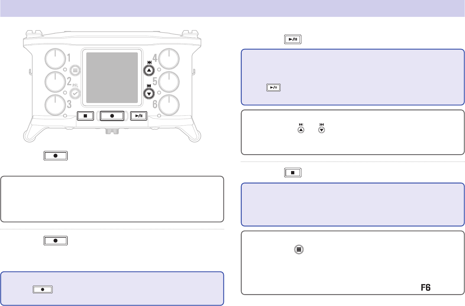
09
Names of parts
SD card slot
L battery lock button
L battery mount
Track knob Display
PLAY/PAUSE
button
REC
button
STOP
button
Status indicator
Red: Input enabled
Green: Playback track
enabled
Orange: PFL monitoring
Unlit: Input disabled
FF/
↑
button
Home Screen: Select playback take
Menu Screen: Select menu item
MENU button
Home Screen: Open Menu Screen
Menu Screen: Return to previous
screen
RWD/
↓
button
Home Screen: Select playback take
Menu Screen: Select menu item
PFL/ENTER button
Home Screen: Open PFL Screen
Menu Screen: Confirm menu item
■ Front
■ Back

10
■ Left side
Inputs 1–6 TIMECODE IN/OUT
■ Right side
Inputs 1–3
USB port
Type-C
LINE OUT jack Zoom wireless adapter (e.g. BTA-1)
Inputs 4–6
Headphone volume
HEADPHONE jack POWER switch
TIMECODE IN/OUT jack
XLR
1:GND
2:HOT
3:COLD
12
3
TRS
TIP: Input to F6
(output from external device)
RING: Output from F6
(input to external device)
SLEEVE: GND
Battery
cover

11
Connecting mics/other devices to Inputs 1–6
Connect dynamic and condenser mics with XLR plugs to Inputs 1–6.
Phantom power (+24 V/+48 V) can be supplied to condenser mics.
( →P.81)
Dynamic mic
(XLR cable)
Condenser mic
(XLR cable)
NOTE
When disconnecting an XLR cable, pull the XLR plug while pushing the con-
nector lock release button.
Connecting line level equipment
Connect XLR cables from keyboards and mixers directly to Inputs 1–6.
Direct input of passive guitars and basses is not supported. Connect
these instruments through a mixer or effects device.
(XLR cable)
Keyboard
(XLR cable)
Mixer
The can record 6 individual tracks that correspond to Inputs 1–6 and a stereo mix of these inputs with left and right tracks.
Mics and the outputs of instruments and audiovisual equipment, for example, can be connected to Inputs 1–6 and recorded to tracks 1–6.
Connecting mics

12
Equipment connection examples
Recording is possible in a variety of situations like these.
While lming
• Input 1: gun mic for main subject sound
• Inputs 2–4: lapel mics for performers
• Inputs 5–6: mics for ambient sound
2
3
1
4
5
6
Ambient
mics
Pin mics
Gun mic
Pin mics
Concert recording
• Inputs 1–2: line inputs for outputs from mixer
• Inputs 3–4: mics for stage performance
• Inputs 5–6: ambient mics for audience sound
PA mixer
Ambient mics
(Audience voices)
Mics
(Stage performance)
2
3
1
4
5
6

13
Display overview
Status icons
Stopped
Recording
Paused
Playing back
Recording/playback
sample rate
Clip indicator
Level meter
Track number
Red: Input enabled
Green: Playback track enabled
Gray: Input disabled
Input link settings are shown by
connected adjacent track numbers.
Frame rate
INT: Internal timecode enabled
EXT: External timecode input enabled
Mono
Stereo
Ambisonic
Counter
During recording: Elapsed/remaining recording time
During playback: Elapsed/remaining playback time
Power type and remaining amount
USB: Power supply connected to port
EXT: L battery
AA: AA batteries
Recording/playback timecode
Recording/playback take name
When stopped, press and hold
to show the name that will be
given to the next recorded take.
HINT
•
When the Home Screen is not open, press and hold
to return to the Home Screen.
• Some of the screen will appear differently when the recording mode is Float (32 bit).
■ Home Screen

14
■ Character input screen
Automatic
input button
Operation
indicator
Text box
Keyboard
Press
Press
Press
Press
abc
#+=
Press
123
*
*
NOTE
• The following characters can be used in project names.
• (space) ! # $ ' ( ) + , - 0 1 2 3 4 5 6 7 8 9 ; = @ A B C D E F G H I J K L M N O P Q
R S T U V W X Y Z [ ] ^ _ ` a b c d e f g h i j k l m n o p q r s t u v w x y z { }

15
■ Editing operations
Move cursor in
text box
Use “ ←” and “ →” to move and press
Select characters
(vertical)
Press
or
Select characters
(horizontal)
Press
or
Conrm
characters
Move the cursor to the character to input, and
press
Delete characters
Move cursor before the character to delete in the
text box, and press
Complete editing
Move cursor to "OK" and press
Cancel editing
Press
■ Automatic input keys
(Date): This automatically inputs the date. Example: 190210
(Time): This automatically inputs the time. Example: 180950
(Scene): This automatically inputs the current scene name.

16
Preparations
Supplying power
Power can be supplied three ways using AA batteries, an L battery or USB.
■ Using an L battery
1. Slide the battery in the direction of the arrow while
pressing it toward the recorder.
NOTE
• Be careful because the battery case could become loose unexpectedly if
the battery compartment cover screw is not tightened rmly.
• Use only one type of batteries (alkaline, NiMH or lithium) at a time.
• After loading AA batteries, set "Power Source" to the correct type of bat-
tery. ( →P.23)
• If the remaining battery power indicator becomes red, turn the power off
immediately and install new batteries.
■ Using AA batteries
1. Loosen the screw in the battery cover on the bottom.
2. Open the battery compartment cover on the bottom,
remove the battery case, and insert 4 AA batteries.
3. Put the case into the compartment.
4. Close the battery cover and tighten the screw.

17
■ Using a USB Type-C cable
1. Connect the cable of the dedicated ZOOM AD-17 AC
adapter to the USB port.
2. Plug the dedicated AC adapter into an outlet.
USB (Type-C)
NOTE
• A 5V mobile battery (commercially-available) can also be connected.
• When connected to a computer, power can be supplied by USB.

18
Loading SD cards
1. Open the SD card slot cover, and insert an SD card.
2. To remove the card: push it further into the slot and
then pull it out.
NOTE
Before using SD cards that have just been purchased or that have been for-
matted on a computer, they must be formatted. To format an SD card, use
Menu > SYSTEM > SD Card > Format.

19
Turning the power on and off
■ Turning the power on
1. Press and hold briey.
The ZOOM logo appears and the power turns on.
NOTE
• The rst time the power is turned on after purchase, the date/time must
be set ( →P.21). This setting can also be changed later.
• If “No Card!” appears on the display, conrm that an SD card is inserted
properly.
• If “Card Protected!” appears on the display, the SD card write-protection is
enabled. Slide the lock switch on the SD card to disable write-protection.
• If “Invalid Card!” appears on the display, the card is not formatted cor-
rectly. Format the card or use a different card. Formatting SD cards
( →P.178)
■ Turning the power off
1. Press and hold briey.
NOTE
Keep pressing it until the ZOOM logo appears on the LCD.

20
Setting the language
1. Press .
2. Use and to select
SYSTEM, and press
.
3. Use and to select
Language, and press
.
4. Use and to select the
desired language, and press
.
NOTE
The rst time the power is turned on after purchase, the language must be
set.
The menu display language can be changed.

21
Setting the date and time
1. Press .
2. Use and to select
SYSTEM, and press
.
3. Use and to select
Settings, and press
.
4. Use and to select
Date/Time, and press
.
▶ Continue to one of the following procedures.
Setting the date and time ……………………………………………………… P.22
Setting the date format ………………………………………………………… P.22
NOTE
• The rst time the power is turned on after purchase, the date/time must
be set.
•
The
has a built-in rechargeable battery for retaining the date and time.
Turning the power on will charge it.
If the power is not turned on for a long time, stored date and time settings
will be reset.
If the Date and Time Setting Screen appears during startup, set them
again.
The date and time set on the are used when recording les, for example.
The date format (order of year, month and day) can also be set.

22
8. When done setting, use
and to select
Enter, and press
.
This completes setting the date and
time.
■ Setting the date format
5. Use and to select
Date Format, and press
.
6. Use and to select
the format, and press
.
Setting Explanation
mm/dd/yy Month, day, year order
dd/mm/yy Day, month, year order
yy/mm/dd Year, month, day order
■ Setting the date and time
5. Use and to select Set
Date/Time, and press
.
6. Set the date and time
Move cursor or change value:
Use
and
Change item value:
Use
and to select
the item, and press
.
7. The item selected to be
changed appears red.
Use
and to change
it, and press
.

23
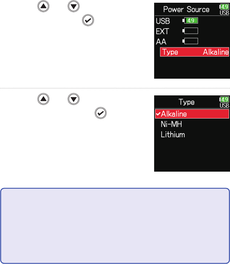
Setting the power supply used
4. Use and to select
Power Source, and press
.
1. Press .
2. Use and to select
SYSTEM, and press
.
3. Use and to select
Settings, and press
.
When using AA batteries, set the battery type so that the amount of remaining power can be shown accurately.
The voltage of each power supply and the remaining battery charge can be checked on this menu page.
24
■ Setting the installed AA battery type
5. Use and to select
Type, and press
.
6. Use and to select
the type, and press
.
NOTE
• When multiple power supplies are connected, they will be used in the fol-
lowing order of priority.
1. USB (Power supply connected to USB port)
2. EXT (L battery)
3. AA (Installed AA batteries)
• The voltages of each power supply are shown on the display.
25
Recording
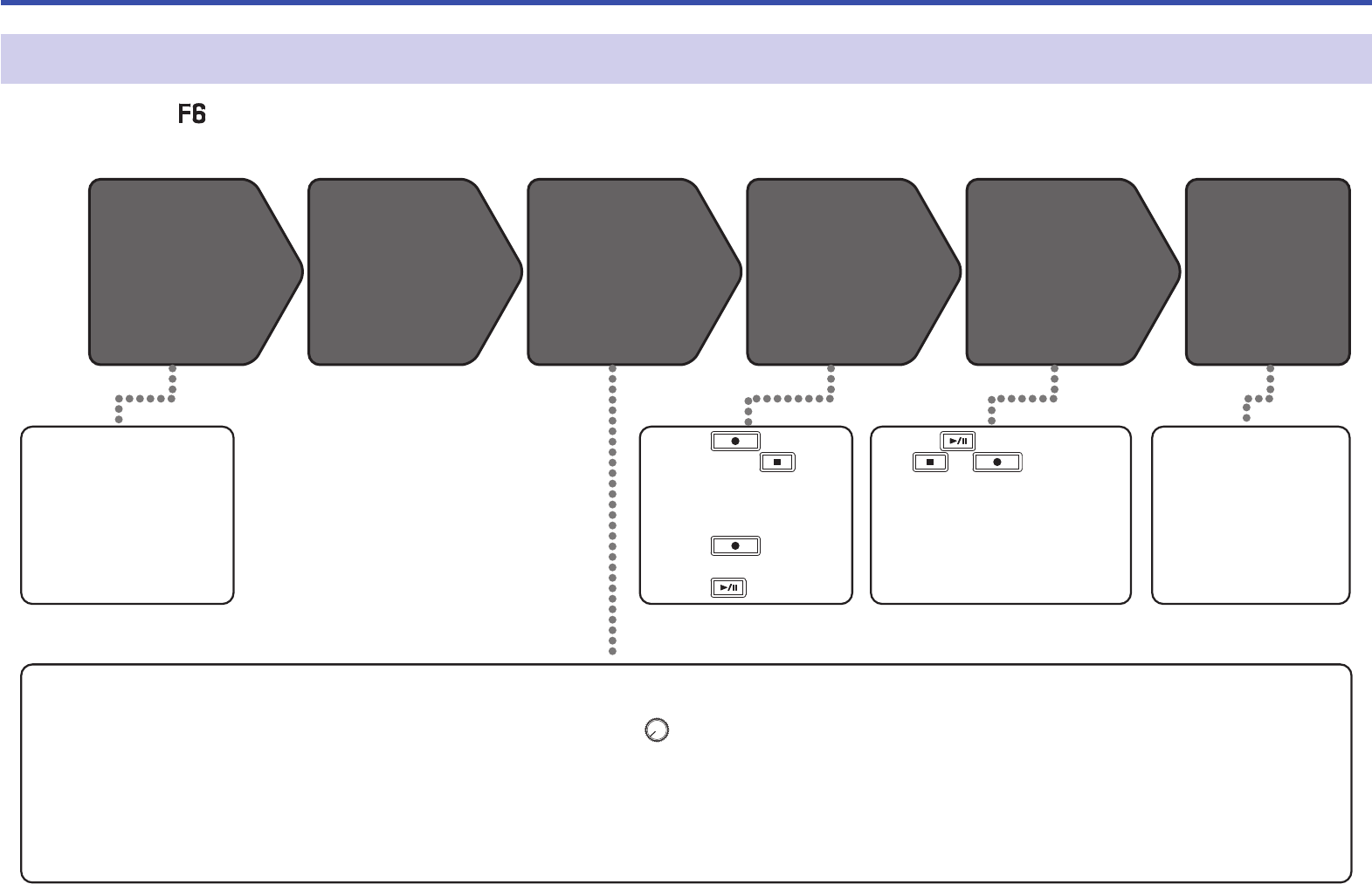
Recording process
Recording with the follows the process shown below.
The data created for each recording occurrence is called a "take".
1. Set the recording mode
(bit depth) ( →P.32).
• Select one of the recording
modes: 16/24-bit WAV, 32-bit
Float WAV, simultaneous
16/24-bit WAV and 32-bit WAV,
or MP3.
2. Set the recording le
• Set the recording le format
( →P.26).
• Set the sampling rate
( →P.30).
3. Select tracks to record
( →P.51).
• Turn the left until it clicks
to disable the input. Input is
enabled at all other positions.
• This can be set to a stereo
track ( →P.99).
4. Make various input and
recording settings
• Settings, including meta-
data ( →P.67), pre-re-
cording ( →P.38), low-cut
lter ( →P.85) and limiter
( →P.87) can be made.
5. Adjust input levels
( →P.28).
• Setting input levels is neces-
sary in some operation modes.
Connect mics, instru-
ments, audiovisual
devices, and other equip-
ment to Inputs 1–6.
( →P.11)
Playing and
checking
( →P.54)
Recording
( →P.29)
Connecting
Turning the
power on
( →P.19)
Preparing to
record
Checking take
information
( →P.67)
・ Press to start
recording and
to
stop.
・ Marks (for cueing) can
also be set.
・ Press
to start
recording the next take.
・ Press to pause.
・ Check and edit
metadata.
・ Press to start playback
and
or to stop.
・ Marks (for cueing), for exam-
ple, can also be set.

26
Setting the recording le format
1. Press .
2. Use and to select
REC, and press
.
3. Use and to select
File Format, and press
.
4. Use and to select the
le format, and press
.
Setting
Tracks
recorded
Explanation
Poly
Selected
tracks 1-6
A single poly le will be created that contains
audio for multiple tracks.
Mono/Stereo
A single mono le is created for each mono
track and a single stereo le is created for
each stereo track.
NOTE
• When recording Mono/Stereo, audio les are saved in a folder that is cre-
ated. ( →P.43)
• This cannot be set when the mode is set to MP3.
27
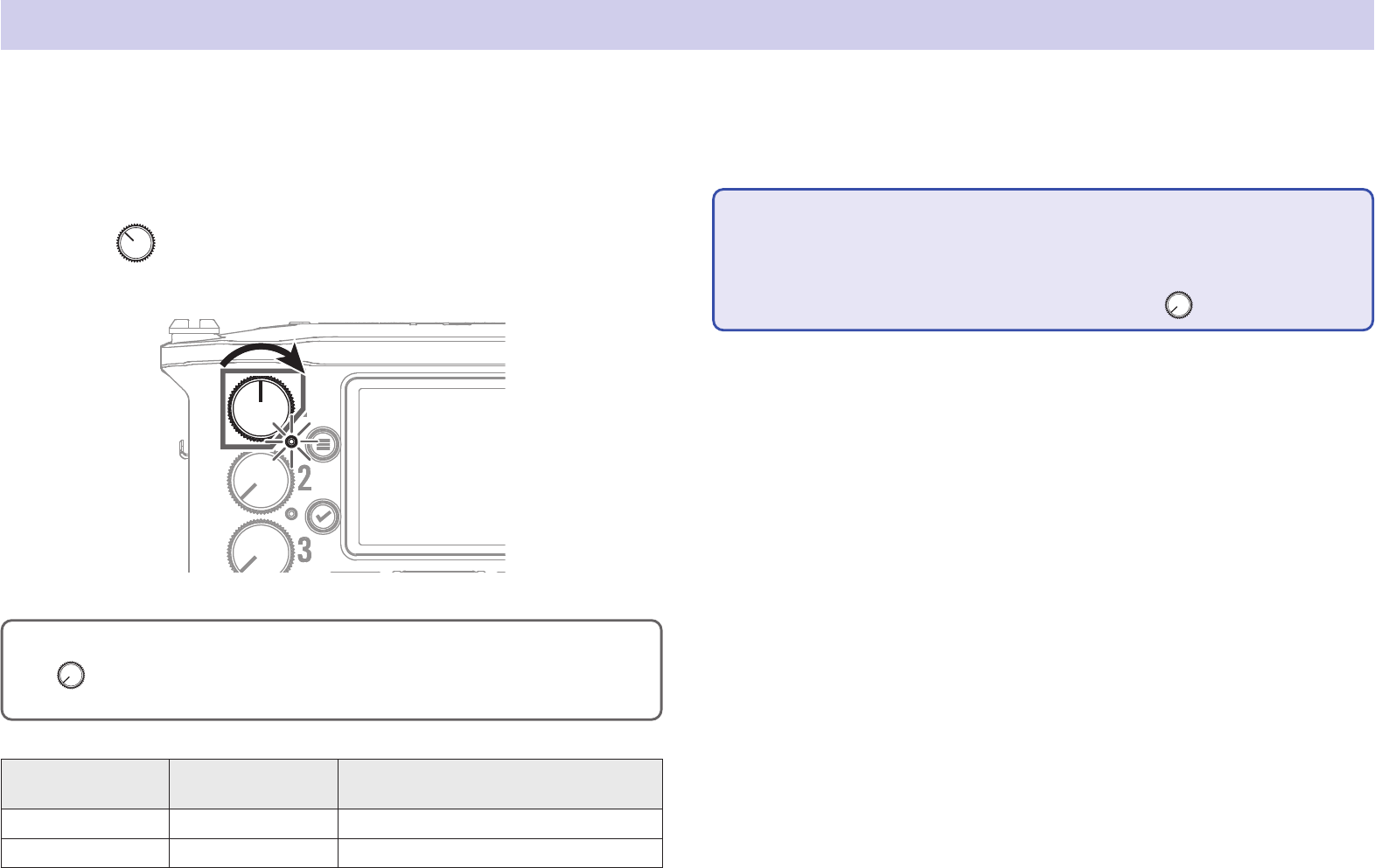
Selecting inputs and adjusting levels
Select which among Inputs 1–6 to use.
Inputs will be recorded on tracks with the same numbers. For example, Input 1 will be recorded on track 1 and Input 2 will be recorded on track 2.
Selecting inputs
1. Turn right for the number of an input to record,
making the track status indicator light.
HINT
Turn left until it clicks to disable the input. Input is enabled at all other
positions.
Track indicator
Track number
background color
Explanation
Lit red Red The input is enabled.
Unlit Gray The input is disabled.
NOTE
• The signals from the inputs selected this way will also be sent to the L/R
tracks.
•
The levels sent to the L/R tracks are adjusted with
.

28
■ Adjusting input levels
1. Press .
2. Use and to select
INPUT, and press
.
3. Use and to select
PFL, and press
.
4. Use and to select the
desired track, and press
.
5. Use and to select
Trim, and press
.
NOTE
Trim cannot be used when the recording mode is set to Float. When set to
Float, the setting is shown as “--”.
6. Use and to adjust the
input level, and press
.
HINT
• This can be set in a range from +12 to +75 dB when the input source is
set to Mic, from –8 to +55 dB when set to Line, and from –35 to +30 dB
when set to USB.
• If the sound distorts even after lowering the input level, try changing mic
positions and adjusting the output levels of connected devices.
• Using the limiter ( →P.87)
• Using the high pass lter ( →P.85)
29
Recording
1. Press .
This starts recording.
HINT
If the timecode function is enabled, recording will start from frame 00 (00
or 02 when using drop frame) and the le length will always be a full sec-
ond value. This makes synchronization easy when editing later.
2. Press to start a new take when recording.
This will end the current take and start a new take while con-
tinuing to record without interruption.
NOTE
Pressing during recording is only possible after recording for at
least a second.
3. Press to pause.
NOTE
• Pausing occurs at whole second increments.
• When recording is paused, a mark is added at that point.
Press
to resume recording.
• A maximum of 99 marks can be added to a take.
HINT
•
During playback,
and can be pressed to jump to places where marks
have been added.
• Marks can be added without pausing. ( →P.170)
4. Press to stop.
NOTE
If the file size exceeds 2GB during recording, a new take will be created
automatically and recording will continue without interruption.
No gap in sound will occur between the two takes when this happens.
HINT
•
Press and hold
when the Home Screen is open to check the name of
the next take recorded.
• Files are automatically saved at regular intervals during recording. If
the power is interrupted or another problem occurs during recording, an
affected le can be restored to normal by playing it with the
.

30
Setting the sampling rate
1. Press .
2. Use and to select
REC, and press
.
3. Use and to select
Sample Rate, and press
.
4. Use and to select the
sampling rate, and press
.
Setting Explanation
44.1 kHz, 48 kHz, 88.2
kHz, 96 kHz, 192 kHz
These are standard sampling rates.
47.952 kHz
Select this when recording video at 23.976 frames
per second in order to edit later at 24 frames per
second.
48.048 kHz
Select this when recording video at 24 frames per
second in order to edit later at NTSC 29.97 or 23.98
HD.
47.952 kHz(F), 48.048
kHz(F)
These function the same as the two above, but the
sampling rate metadata will be recorded as 48 kHz
for <FILE_SAMPLE_RATE>.
This enables playback and editing with devices and
software that do not support 47.952 kHz and 48.048
kHz WAV les. Playback, however, will occur at the
±0.1% speed at which the le was recorded.
The sampling rate used to record les can be set.

31
NOTE
• 192 kHz cannot be selected when the recording mode is Float (32bit) and
the LR track is on.
• When 192 kHz is selected, Dual (16+32bit) and Dual (24+32bit) cannot be
set.
• When the recording mode is MP3, only 44.1 kHz and 48 kHz can be
selected.
• When 192 kHz is selected, L/R tracks will not be recorded. Input and out-
put delay are also disabled.
• The Limiter cannot be set to On (Advanced) if Auto Mix is On or the Ambi-
sonic format is not set to Off.
• AIF with Rec cannot be used when values other than 44.1 kHz or 48 kHz
are selected.

32
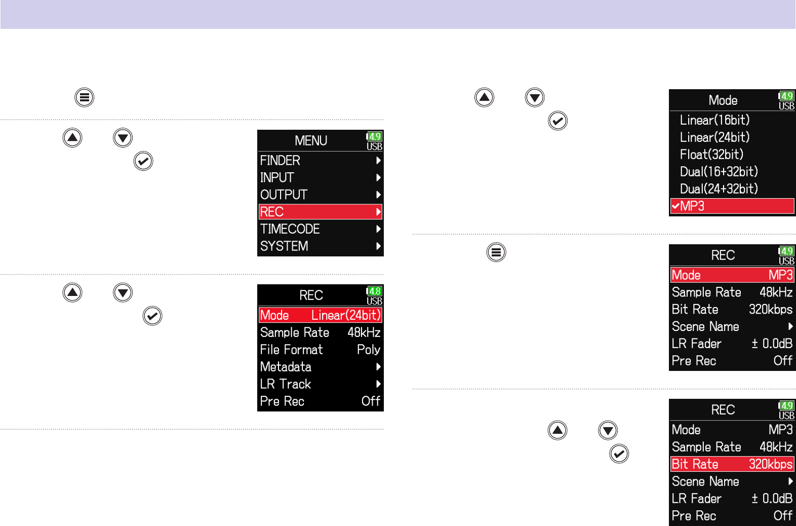
Setting the recording mode (bit depth)
1. Press .
2. Use and to select
REC, and press
.
3. Use and to select
Mode, and press
.
4. Use and to select
the mode, and press
.
HINT
The setting options are Linear (16bit), Linear (24bit), Float (32bit), Dual
(16+32bit), Dual (24+32bit) and MP3.
Set the recording mode.
The bit depth of WAV les recorded by the will change according to the mode setting.

33
Mode setting Mode name Explanation
Linear (16bit)
Linear
These modes record ordinary 16/24-
bit WAV les.
Adjust input (trim) levels so that
the clip indicators do not light when
recording. The level meters show input
levels after adjustments.
Linear (24bit)
Float (32bit) Float
This mode records 32-bit oat WAV
les. Adjusting input levels is unneces-
sary. As long as maximum input levels
are not exceeded, both quiet and loud
sounds can be recorded with high
quality.
The level meters show levels after
adjustments by
knobs.
Dual (16 + 32bit)
Dual
These modes simultaneously record
ordinary 16/24-bit WAV les and 32-bit
oat WAV les.
Adjust input (trim) levels so that
the clip indicators do not light when
recording.
Even if clipping occurs in 16/24bit
WAV le data during recording, data
at a suitable level without clipping can
be obtained by editing the 32bit Float
WAV les during post-production.
Dual (24 + 32bit)
MP3 MP3
This mode records MP3 les.
Trim setting is necessary in this mode.
NOTE
• When Float (32bit) is selected, if a signal is input that exceeds the maxi-
mum input level for the input source (+4 dBu when Mic or +24 dBu when
Line), an “Exceeding maximum input level” message will appear. If this
message appears, adjust the output levels of the devices connected to
the input jacks.
• When Float (32bit) is selected, the limiter cannot be changed from off and
the AIF with Rec function cannot be used. Moreover, Float (32bit) cannot
be selected if the sample rate is 192 kHz and the LR track is on.
• When Dual (16 + 32 bit) or Dual (24 + 32bit) is selected, the limiter cannot
be changed from off and the sample rate cannot be set to 192kHz.
34
Setting MP3 le bit rate (MP3)
1. Press .
2. Use and to select
REC, and press
.
3. Use and to select
Mode, and press
.
4. Use and to select
MP3, and press
.
5. Press to return to
the REC screen.
6. Conrm that the Mode is set to
MP3. Then, use
and to
select Bit Rate, and press
.
The bit rate used for recording MP3 les can be set.

35
7. Use and to select
the bit rate, and press
.
HINT
This can be set to 128 kbps, 192 kbps or 320 kbps.

36
Setting the LR Track
4. Use and to select
On/Off, and press
.
5. Use and to select
On, and press
.
NOTE
• Off: This disables the LR Track.
• On: This enables the LR Track. All selected tracks and the LR Track will be
recorded.
• On (LR only): This enables the LR Track. Only the LR Track will be
recorded.
• On cannot be selected if the sample rate is 192 kHz and the recording
mode is Float (32bit).
■ Enabling the LR track
1. Press .
2. Use and to select
REC, and press
.
3. Use and to select
LR Track, and press
.

37
■ Adjusting the L/R track volume
1. Press .
2. Use and to select
REC, and press
.
3. Use and to select
LR Track, and press
.
4. Use and to select
LR Fader, and press
.
5. Use and to select
LR Fader, and press
.
6. Use and to change
the LR fader value, adjust-
ing the LR track volume.
NOTE
Pressing + when the Home Screen is open will also open the LR/
Line Out setting screen.

38
Capturing audio before recording starts
1. Press .
2. Use and to select
REC, and press
.
3. Use and to select
Pre Rec, and press
.
4. Use and to select
On, and press
.
Sample Rate Maximum pre-recording time
WAV
44.1 kHz 6 seconds
48 kHz 6 seconds
88.2 kHz 3 seconds
96 kHz 3 seconds
192 kHz 1 second
47.952 kHz 6 seconds
47.952 (F) kHz 6 seconds
48.048 kHz 6 seconds
48.048 (F) kHz 6 seconds
MP3
44.1 kHz 6 seconds
48 kHz 6 seconds
NOTE
Pre-recording will be disabled if MENU > TIMECODE > Mode ( →P.127) is
set to Int Record Run, Ext or Ext Auto Rec.
The input signal is always buffered for a set amount of time, so it can be captured for up to 6 seconds before is pushed (pre-recording). This
is useful when is pressed late, for example.

39
Setting the recording time display
1. Press .
2. Use and to select
SYSTEM, and press
.
3. Use and to select
Settings, and press
.
4. Use and to select
Display, and press
.
5. Use and to select
Time Display, and press
.
During recording, either the elapsed recording time or the remaining possible recording time can be shown.

40
6. Use and to select
Recording, and press
.
7. Use and to select the
time to show, and press
.
NOTE
When recording for a long time, if the le size
exceeds 2 GB, recording will continue in a new
le and the recording time will reset. This can
be changed, however, so that it is not reset and
the total recording time is shown.
Set Rec Time Reset on the Time Display screen
to On/Off to set whether or not recording time
resets when a new le is created.
Off: When recording, even if the file size
reaches 2GB, the counter shown on the
Home Screen will not reset.
On (reset): When recording, if the file size
reaches 2GB, the counter shown on the
Home Screen will be reset to 000:00:00.

41
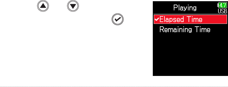
Setting the playback time display
1. Press .
2. Use and to select
SYSTEM, and press
.
3. Use and to select
Settings, and press
.
4. Use and to select
Display, and press
.
5. Use and to select
Time Display, and press
.
6. Use and to select
Playing, and press
.
During playback, either the elapsed playback time or the remaining playback time can be shown.
42
7. Use and to select the
time to show, and press
.

43
Folder and le structure
When recording with the , folders and les are created on the SD card in the following manner.
folders and les are used to manage scenes and takes as a rule.
190101_001.WAV
190101_003.TAKE
190101_003_Tr1.WAV
190101_003_Tr2.WAV
190101_003_Tr3.WAV
190101_003_Tr4.WAV
Scene 190101 (3rd take)
WAV format
Mono files (tracks 1–4)
Stereo file (tracks 5, 6)
Stereo file (tracks L, R)
Scene001 (3rd take)
WAV format
Mono files (tracks 1–4)
Stereo file (tracks 5, 6)
Stereo file (tracks L, R)
Scene 190101
(1st take)
WAV format
polyphonic file
Scene 190101
(2nd take)
MP3 format
stereo file
Scene001
(1st take)
WAV format
polyphonic file
Scene001
(2nd take)
MP3 format
stereo file
Scene001
190101_003_Tr5_6.WAV
190101_003_TL_R.WAV
Scene001_001.WAV Scene001_002.MP3
Scene001_003.TAKE
Scene001_003_Tr1.WAV
Scene001_003_Tr2.WAV
Scene001_003_Tr3.WAV
Scene001_003_Tr4.WAV
Scene001_003_Tr5_6.WAV
Scene001_003_TL_R.WAV
Scene002
Scene 1
(Folder created by user)
Scene 2
(Folder created by user)
Root
Recording order
→
Recording when scene naming is set to “Date”
Recording when scene naming is set to “Current Folder”
190101_002.MP3
Scene00 (3rd take)
WAV format
Mono files (tracks 1–4)
Stereo file (tracks 5, 6)
Stereo file (tracks L, R)
Scene002
(1st take)
WAV format
polyphonic file
Scene002
(2nd take)
MP3 format
stereo file
Scene002_001.WAV Scene002_002.MP3
Scene002_003.TAKE
Scene002_003_Tr1.WAV
Scene002_003_Tr2.WAV
Scene002_003_Tr3.WAV
Scene002_003_Tr4.WAV
Scene002_003_Tr5_6.WAV
Scene002_003_TL_R.WAV
Folder and le structure
The folder and le structure differs according to the recording le for-
mat. In addition, the names of folders and les depend on how scenes
are named.
NOTE
• Setting the recording le format ( →P.26)
• Setting how scenes are named (mode) ( →P.48)
HINT
Take: This is a unit of data created for a single recording.
Scene: This is a unit containing multiple files and takes that comprise a
single scene.

44
■ Take names
Structure Explanation
Scene001-001
Take number
(001–999)
Scene number
(1-9999)
Scene
Name
Scene name: Select none, the folder
name, the date or a name input by the
user ( →P.48).
Scene number: Press
+ to
increase the number by one.
Take number: This number increases
by 1 with each recording made with
the same scene name and scene
number.
■ Audio le names
File names given by the differ according to polyphonic, mono and
stereo file formats. Track numbers and other data are added to file
names.
File names
File names are given according in the following formats.
Type Structure Explanation
Poly le
Scene001-001.wav
Take name
This is a le created by
polyphonic recording.
Audio for multiple tracks
is recorded to a single
le.
Mono le
Scene001-001_Tr1.wav
Take name
Track number
This is a le created by
monophonic recording.
Stereo le
Scene001-001_Tr1_2.wav
Take name
Track number
This is a le created by
stereophonic recording.
Float le
in Dual
mode
Scene001_001_32FP.wav
Float le characters
This is a 32bit Float
WAV le created when
in Dual recording mode.
Long
recording
le
Scene001_001_0002.wav
Long recording le number
This is a le created
automatically when the
le size exceeded 2 GB
during recording. The
long recording le num-
ber increases one each
time the le changes.
HINT
When recording with a Mono/Stereo setting, the audio les are saved in a
take folder that is created.

45
Move the previously recorded take to the FALSE TAKE folder.
1. Open the Home Screen.
2. While pressing , press .
HINT
• Moving a take to the FALSE TAKE folder reduces the take number by one.
• Even during recording, the previously recorded take can be moved to the
FALSE TAKE folder.
3. Use and to select
Execute, and press
.
If the just recorded take was a failure, a shortcut can be used to move the recording to the FALSE TAKE folder.

46
1. Press .
2. Use and to select
REC, and press
.
3. Use and to select
Metadata, and press
.
▶ Continue to one of the following procedures.
Editing notes …………………………………………………………………………… P.46
Selecting notes from the history list …………………………………… P.47
■ Editing notes
4. Use and to select
Note, and press
.
5. Use and to select
Edit, and press
.
Recorded take settings
Changing the note for the next take recorded
Characters can be input, for example, as a note to use as metadata in les.

47
6. Edit the note.
See "Character input screen"
( →P.14) for how to input
characters.
NOTE
This note is written to the <NOTE> metadata.
■ Selecting notes from the history list
5. Use and to select
History, and press
.
6. Use and to select
the desired history
item, and press
.
NOTE
The history list will be erased if the Factory Reset function is used.
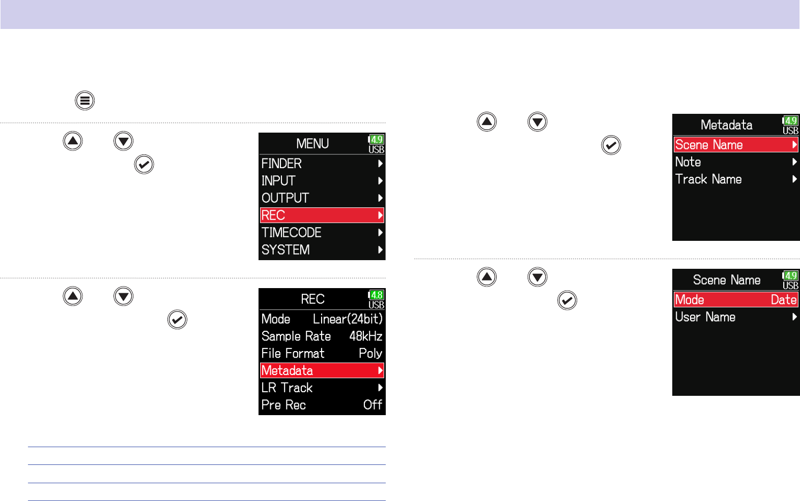
48
1. Press .
2. Use and to select
REC, and press
.
3. Use and to select
Metadata, and press
.
▶ Continue to one of the following procedures.
Setting how scenes are named (mode) ……………………………… P.48
Changing scene names ………………………………………………………… P.49
Selecting a scene name from the history list …………………… P.50
■ Setting how scenes are named (mode)
4. Use and to select
Scene Name, and press
.
5. Use and to select
Mode, and press
.
Setting and managing recorded scene names
The way scenes are named (name mode) can be set.

49
■ Changing scene names
If Scene Name Mode is set to User Name, set the scene name used like
this.
4. Use and to select
User Name, and press
.
5. Use and to select
Edit, and press
.
6. Edit the scene name.
See "Character input screen"
( →P.14) for how to input
characters.
Setting Explanation
Current
Folder
The name of the currently selected folder is used as the scene
name.
+
can be used to advance the scene number by 1. After
advancing the scene number by 1, the corresponding folder will
be used as the recording destination. If that folder does not
already exist, it will be created.
Example: FOLDER001-001.wav
Date
The date is used as the scene name.
+
cannot be used to advance the scene number by 1.
Example: 20190101-001.wav
User Name
A scene name input by the user is used.
+
can be used to advance the scene number by 1.
Example: MYSCENE001-001.wav

50
6. Use and to select
the desired history
item, and press
.
NOTE
The history list will be erased if the Factory Reset function is used.
NOTE
• The scene name is written to the <SCENE> metadata.
• Spaces and @ marks cannot be input at name beginnings.
■ Selecting a scene name from the history list
4. Use and to select
User Name, and press
.
5. Use and to select
History, and press
.

51
1. Press .
2. Use and to select
REC, and press
.
3. Use and to select
Metadata, and press
.
4. Use and to select
Track Name, and press
.
5. Use and to select
a track, and press
.
▶ Continue to one of the following procedures.
Editing the track name …………………………………………………………… P.52
Selecting a track name from the history list ……………………… P.52
Changing the track name of the next take recorded (Track Name)
The track name set with the following procedure will be given to the next recorded track.

52
■ Editing the track name.
6. Use and to select
Edit, and press
.
7. Edit the track name.
See "Character input screen"
( →P.14) for how to input
characters.
NOTE
The track name is written to the <TRACK> <NAME> metadata.
■ Selecting a track name from the history list
6. Use and to select
History, and press
.
7. Use and to select
the desired history
item, and press
.
NOTE
The history list will be erased if the Factory Reset function is used.

53
The number given to the next recorded take can be changed when the Home Screen is open.
1. While pressing , press .
2. Use or to increase
or decrease the take num-
ber, and press
.
Changing the number of the next take recorded

54
1. Press .
■ Playback operations
Select take/Jump to mark: Press /
Search backward/forward: Press and hold /
Pause/resume playback: Press
NOTE
Track backgrounds will appear black.
HINT
•
The longer / is pressed and held, the faster the speed of searching
backward/forward.
• An "Invalid Take!" message will appear if the selected take is not valid.
• A "No Take!" message will appear if no playable take exists.
•
During playback, press
to add marks that can be used for skipping.
(
→
P.170)
2. Press to return to the Home Screen.
Playback
Playing recordings

55
Mixing takes
The volume and panning of each track during playback can be changed.
■ Setting faders
1. Touch on the Home
Screen ( →P.13).
2. Turn to adjust the
input signal level.
NOTE
Turn left until it clicks to mute the input.
■ Setting the panning
1. Press .
2. Use and to select
INPUT, and press
.
3. Use and to select
PFL, and press
.

56
5. Use and to select the
desired track, and press
.
6. Use and to select
Pan, and press
.
7. Adjust the panning.
Parameter Setting range Explanation
Fader
(in Float mode)
Mute, −60.0 – +60.0 dB
Adjusts the input signal level.
Fader
(in Linear mode)
Mute, −48.0 – +24.0 dB
Pan L100 – Center – R100
Adjusts the stereo balance of
the sound.
NOTE
• Settings are saved separately for each take and are used during playback.
• Mix settings are not saved with the take when the recorded le format is
MP3.

57
Monitoring the playback signals of specic tracks during playback
The playback signals of specic tracks can be monitored using SOLO mode.
1. Open the Home Screen.
2. Press to start playback.
3. Press during playback.
4. Use and to select
INPUT, and press
.
NOTE
SOLO mode can only be used with tracks that can be played back (indica-
tors lit green).
5. Use and to select
PFL, and press
.
58
6. Use and to select the
track to monitor, and press
.

59
Changing the repeat playback setting
1. Press .
2. Use and to select
PLAY, and press
.
3. Use and to select
Repeat, and press
.
4. Use and to select the
repeat mode, and press
.
Setting Explanation
Play One
(single playback)
Only the selected take will be played.
Play All
(all playback)
Takes will be played back continuously from the
selected one until the last one.
Repeat One
(single repeat playback)
The selected take will be played repeatedly.
Repeat All
(all repeat playback)
All takes in the selected folder will be played
repeatedly.
HINT
The PLAY menu only appears during playback.
The repeat setting used during playback can be changed.

60
Take and folder operations
Working with takes and folders
The Finder allows the viewing of the contents of SD cards, takes and folders and the creation of project/scene folders. It also allows the setting and
deletion of recording/playback folders along with viewing their information, for example.
1. Press .
2. Use and to select
FINDER, and press
.
3. Use and to select the
SD card, and press
.
■ Editing operations
Cursor: Press /
Move down a level (next): Press
Move up a level (previous): Press
Show Option screen: Press and hold
NOTE
•
When the cursor is on a take, pressing
will play the selected take.
, and can also be used.
• A check mark appears on the playback take and recording/playback
folder.
▶ Continue to one of the following procedures.
Creating folders ……………………………………………………………………… P.61
Selecting the take recording/playback folder …………………… P.61
Checking take marks and using them for playback ………… P.62
Changing folder and take names ………………………………………… P.62
Deleting folders and takes …………………………………………………… P.63
Emptying the TRASH/FALSE TAKE folders ………………………… P.64

61
■ Creating folders
Folders can be created inside the currently selected SD card/folder.
4. Use and to select
New Folder, and press
.
5. Edit the folder name.
See "Character input screen"
( →P.14) for how to input
characters.
NOTE
• The folder created will be set as the recording folder.
• The name of the folder created is written to the <PROJECT> or <SCENE>
metadata of the recorded take.
• Spaces and @ marks cannot be input at name beginnings.
■ Selecting the take recording/playback folder
Use this procedure to select the folder that contains the take to be
played back or the folder to use for recording takes and return to the
Home Screen.
4. Press and hold to open the Option screen.
5. Use and to select
Select, and press
.
NOTE
•
Select a folder or take before pressing and holding
to open the Option
screen.
• The rst take inside the selected SD card or folder will be set as the play-
back take.

62
■ Changing folder and take names
4. Press and hold to open the Option screen.
5. Use and to select
Rename, and press
.
6. Edit the folder/take name.
See "Character input screen"
( →P.14) for how to input
characters.
NOTE
• The edited name of the folder/take is written to the <PROJECT> or
<SCENE> metadata.
• Spaces and @ marks cannot be input at name beginnings.
■ Checking take marks and using them for playback
A list of the marks in a recorded take can be shown.
4. Press and hold to open the Option screen.
5. Use and to select
Mark List, and press
.
6. Use and to select a mark, and press .
The Home Screen will reopen, and playback will start from the
mark.
Added mark
Mark added when
skipping occurred
during recording and
its time

63
■ Deleting folders and takes
4. Press and hold to open the Option screen.
5. Use and to select
Delete, and press
.
6. Use and to select
the folder/take to delete,
and press
.
Press to cancel deletion.
NOTE
Press to select/deselect all the folders and takes that are currently
shown.
7. Press and hold .
8. Use and to select
Execute, and press
.
NOTE
• Deleted folders and takes are not immediately erased from the SD card.
They are moved to the TRASH folder.
• Deleting folders and takes in the TRASH folder will completely erase their
data.

64
■ Checking folder and take information
4. Press and hold to open the Option screen.
5. Use and to select
Info, and press
.
■ SD card selected
Free: Open space
Size: Card capacity
Remain: Remaining recording time
■ Folder selected
Date: Date
Time: Time
■ Take selected
TC: Timecode
FPS: Timecode frame rate
Len: Take recording length
Fmt: Take sample format
Date: Date
Time: Time
Size: Take size

65
■ Emptying the TRASH/FALSE TAKE folders
4. Use and to select
TRASH or FALSE TAKE.
5. Press and hold .
TRASH folder
FALSE TAKE folder
6. Use and to select
Empty, and press
.
7. Use and to select
Execute, and press
.
NOTE
• Emptying the TRASH folder will completely erase the data in it.
• Emptying the FALSE TAKE folder does not immediately erase its data
from the SD card. The data is moved to the TRASH folder.

66
Overview of metadata (take information) stored in les
The writes a variety of information (metadata) to les during record-
ing.
When these les are read by an application that supports metadata, the
saved information can be checked and used.
HINT
•
Metadata is data that contains information related to other data. The
saves scene names and take numbers, for example, as metadata in audio
les.
• A chunk is a unit that contains multiple data in a single block.
• To use BEXT and iXML chunk metadata, an application that supports
both data formats is necessary.
■ WAV le metadata
The metadata saved in les recorded by the in WAV format is col-
lected in BEXT (Broadcast Audio Extension) and iXML chunks.
For details about the metadata saved in these chunks, see "Metadata
contained in BEXT chunks in WAV files" ( →P.188), "Metadata con-
tained in iXML chunks in WAV les" ( →P.189).
■ MP3 le metadata
The metadata saved in les recorded by the in MP3 format is writ-
ten as ID3v1 tags.
For information about the ID3 fields and formats saved as metadata,
see "Metadata and ID3 elds contained in MP3 les" ( →P.191).
HINT
•
MP3 les conform to the MPEG-1 Layer III standard.
• MP3 metadata cannot be edited.

67
Checking and editing take metadata
1. Press .
2. Use and to select
FINDER, and press
.
3. Use and to select an
SD card, and press
.
4. Use and to select
a folder, and press
.
5. Use and to select
a take, and press
.
This opens the Option screen.
See "Take and folder operations" for
how to use the Finder ( →P.60).
6. Use and to select Meta-
data Edit, and press
.

68
▶ Continue to one of the following procedures.
Checking and editing notes ………………………………………………… P.68
Selecting notes from the history list …………………………………… P.69
Checking and editing scene names …………………………………… P.69
Selecting a scene name from the history list …………………… P.70
Checking and editing take names ……………………………………… P.71
Circling takes ………………………………………………………………………… P.72
Changing tape names …………………………………………………………… P.72
Changing project names ……………………………………………………… P.73
Checking and editing track names ……………………………………… P.73
Selecting a track name from the history list ……………………… P.74
■ Checking and editing notes
7. Use and to select
Note, and press
.
8. Use and to select
Edit, and press
.
9. Edit the note.
See "Character input screen"
( →P.14) for how to input
characters.
NOTE
The contents of this note is written to the <NOTE> metadata.

69
■ Checking and editing scene names
7. Use and to select
Scene/Take, and press
.
8. Use and to select
Scene, and press
.
9. Use and to select
Edit, and press
.
■ Selecting notes from the history list
7. Use and to select
Note, and press
.
8. Use and to select
History, and press
.
9. Use and to select
the desired history
item, and press
.
NOTE
The history list will be erased if the Factory Reset function is used.

70
10. Edit the scene name.
See "Character input screen"
( →P.14) for how to input
characters.
NOTE
The scene name is written to the <SCENE> metadata.
■ Selecting a scene name from the history list
7. Use and to select
Scene/Take, and press
.
8. Use and to select
Scene, and press
.
9. Use and to select
History, and press
.
10. Use and to select
the History item to use,
and press
.
NOTE
The history list will be erased if the Factory Reset function is used.

71
■ Checking and editing take numbers
7. Use and to select
Scene/Take, and press
.
8. Use and to select
Take, and press
.
9. Change the take number.
■ Editing operations
Move cursor or change value: Press /
Select parameter to change: Press
HINT
This can be set from 1 to 999.
NOTE
The take number is written to the <TAKE> metadata.
10. When done changing,
use
and to select
Enter, and press
.

72
■ Circling takes
An @ mark can be added to the beginning of the name of the best take
to make it stand out. This is called a "circled take".
7. Use and to select
Circle, and press
.
8. Use and to select
Circled, and press
.
NOTE
•
To clear a circle, select Not Circled and press
.
• This circled status is written to the <CIRCLE> metadata.
■ Changing tape names
7. Use and to select
Tape Name, and press
.
8. Edit the folder (tape) name.
See "Character input screen"
( →P.14) for how to input
characters.
NOTE
• The folder (tape) name is written to the <TAPE> metadata.
• The folder (tape) name used immediately after recording is the name of
the folder in which the take was recorded.

73
■ Changing project names
7. Use and to select Proj-
ect Name, and press
.
8. Edit the project name.
See "Character input screen"
( →P.14) for how to input
characters.
NOTE
• The project name is written to the <PROJECT> metadata.
• The project name used immediately after recording is the name of the
highest level folder (inside the SD card root directory) that contains the
folder in which the take was recorded.
■ Checking and editing the track names
7. Use and to select
Track Name
, and press
.
8. Use and to select
a track, and press
.
9. Use and to select
Edit, and press
.

74
10. Edit the track name.
See "Character input screen"
( →P.14) for how to input
characters.
NOTE
The track name is written to the <TRACK> <NAME> metadata.
■ Selecting a track name from the history list
7. Use and to select
Track Name, and press
.
8. Use and to select
a track, and press
.
9. Use and to select
History, and press
.

75
10. Use and to select the
desired history, and press
.
NOTE
The history list will be erased if the Factory Reset function is used.

76
4. Use and to select
Sound Report, and press
.
▶ Continue to one of the following procedures.
Writing sound reports …………………………………………………………… P.77
Editing comments ………………………………………………………………… P.77
Selecting comments from the history list …………………………… P.78
1. Press .
2. Use and to select
FINDER, and press
.
3. Use and to select the
folder or SD card desired
for sound report creation,
and press and hold
.
Writing a sound report
A sound report includes information about recording times and takes.
Reports can be written as CSV format les (F6_[folder name].CSV).
Comments written in sound reports can also be edited.

77
■ Editing comments
5. Use and to select
Info, and press
.
6. Use and to select
Edit, and press
.
7. Edit the comment.
See "Character input screen"
( →P.14) for how to input
characters.
■ Writing sound reports
5. Use and to select
Create, and press
.
6. Use and to select
Execute, and press
.
This writes the sound report inside
the selected SD card or folder.
NOTE
• Only information about takes in the folder or SD card is written in the
sound report.
• Be careful because a sound report file with the same name will be
overwritten.

78
7. Use and to select
the desired history
item, and press
.
NOTE
The history list will be erased if the Factory Reset function is used.
■ Selecting comments from the history list
5. Use and to select
Info, and press
.
6. Use and to select
History, and press
.

79
Adjusting the input signal monitoring balance
1. Open the Home Screen
( →P.13).
2. Use to adjust the faders.
HINT
The fader setting range depends on the recording mode. In Float mode, it
is muted and −60.0 to +60.0 dB. In Linear mode, it is muted and −48.0 to
+24.0 dB.
NOTE
• Mix settings are saved separately for each recorded take and can be
changed during playback ( →P.55).
• Mix settings are not saved with the take when the recorded le format is
MP3.
The volume of each track can be adjusted when monitoring input signals.
Input settings

80
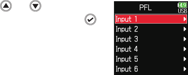
Monitoring the input signals of specied tracks
1. Press when the Home Screen is open.
The PFL screen for the track that was last opened opens, and the
status indicator lights orange.
Only the input sound of the track show can be monitored through
headphones.
Level meter
(pre-fader input
signal level)
Parameter name
Parameter Explanation
Source This sets the input source.
Trim This sets the input level.
HPF/Limiter This sets the high pass lter and limiter.
Phase/Delay This sets the phase reversal and delay.
Pan This sets the panning.
Monitor This sets the monitoring volume on the PFL screen.
NOTE
This does not change the signals output from line outputs.
HINT
•
Use
and to select parameters and change setting values.
• When the cursor is on the topmost track number, press
to show the
next track.
2. Press .
This opens the Home Screen.
The input signals of specied tracks can be monitored.
Even tracks that have not been set to record can be input to the PFL screen and their input sounds monitored.
This is convenient when using tracks as return inputs.
Carious settings can be made for selected tracks.

81
Setting the input source
The input source and phantom power on/off status can be set for each track.
1. Press .
2. Use and to select
INPUT, and press
.
3. Use and to select
PFL, and press
.
4. Use and to select
a track, and press
.
5. Use and to select
Source, and press
.
6. Use and to select the
input source, and press
.

82
Setting Explanation
Mic
Use when connecting a mic or other equipment with a
low input level.
Mic (PH) Use for mic level with phantom power.
Line
Use when connecting line level equipment.
The input level will be reduced 20 dB compared to when
Mic is selected.
Line (PH) Use this setting for line level with phantom power.
USB 1–4
When AIF with Rec ( → P.143) is set to On, computer
output signals are treated as input signals
HINT
For phantom power voltage, see “Changing the phantom power settings”
( →P.95).

83
1. Press .
2. Use and to select
INPUT, and press
.
3. Use and to select
PFL, and press
.
4. Use and to select
a track, and press
.
5. Use and to select
Monitor, and press
.
6. Use and to select
the mode, and press
.
Setting the monitoring volume on the PFL screen
On the PFL screen, the monitoring sound can be set to be either pre-fader listening (PFL) or fader solo (SOLO).

84
Setting Explanation
PFL On the PFL screen, monitor the pre-fader sound.
SOLO On the PFL screen, monitor the post-fader sound.
NOTE
• When the PFL screen is open during playback, the monitoring sound will
be post-fader (SOLO) regardless of the setting.
• The pre-fader and post-fader monitoring positions depend on the set
recording mode. See the block diagrams for details about the positions (→
“Block diagrams” on P.193).

85
Cutting low-frequency noise
1. Press .
2. Use and to select
INPUT, and press
.
3. Use and to select
PFL, and press
.
4. Use and to select
a track, and press
.
5. Use and to select
HPF/Limiter, and press
.
6. Use and to select
HPF, and press
.
The high pass lter can cut low frequencies to reduce the sound of wind, vocal pops and other noise.

86
7. Use and to select
the desired cutoff fre-
quency, and press
.
HINT
This can be set to Off or between 10 and 240 Hz.

87
Input limiter
The limiter can prevent distortion by reducing input signals that have
excessively high levels.
Attack
time
Threshold
Level
Input signal
Signal after
limiter
Release
time
Time
When the limiter is ON, if the input signal level exceeds the set thresh-
old value, the input signal level will be suppressed to prevent the sound
from distorting.
The amount of time after the input signal exceeds the threshold until
compression of the output signal is maximized is called the “attack
time”. The amount of time after the input signal goes below the thresh-
old until the limiter stops compressing the signal is called the “release
time”. Change these two to adjust the audio quality.
1. Press .
2. Use and to select
INPUT, and press
.
3. Use and to select
PFL, and press
.
4. Use and to select
a track, and press
.

88
5. Use and to select
HPF/Limiter, and press
.
6. Use and to select
Limiter, and press
.
▶ Continue to one of the following procedures.
Using the limiter ……………………………………………………………………… P.88
Setting the type ……………………………………………………………………… P.90
Setting the threshold ……………………………………………………………… P.90
Setting the attack time ………………………………………………………… P.91
Setting the release time ………………………………………………………… P.91
Setting the target level …………………………………………………………… P.92
Using the limiter
7. Use and to select
On/O
, and press
.
8. Use and to select
the setting, and press
.

89
On (Normal)
On (Advanced)
Before limiter use After limiter use
Sometimes peaks remain
Before limiter use After limiter use
Threshold
Target level
Sudden peaks are
prevented by looking
ahead for maximum levels
Setting Explanation
Off This disables the limiter.
On (Normal) This applies an ordinary limiter. The ratio is 20:1.
On
(Advanced)
By detecting the maximum level in advance, this optimized lim-
iter prevents distortion even more than ordinary limiter opera-
tion. The ratio is ∞:1, providing increased internal headroom.
NOTE
When set to On (Advanced), the input latency of the increases 1 ms.
When monitoring sounds being recorded with a mic in real-time, increased
latency can cause interference between the sound being recorded that
is transmitted through the air and the delayed monitored sound, possibly
making accurate monitoring dicult.
NOTE
• When set to On (Advanced), the Sample Rate cannot be set to 192 kHz.
• Moreover, when the Sample Rate is set to 192 kHz, the On (Advanced)
setting cannot be selected.

90
■ Setting the type
7. Use and to select
Type, and press
.
8. Use and to select
the type, and press
.
Setting Explanation
Hard Knee
Only peaks that exceed the threshold are attenuated. There is
no effect below the threshold.
Soft Knee
The limiter gradually affects the signal about 6 dB below the
threshold for a gentler effect.
NOTE
This setting becomes available when On/Off is set to On (Normal).
■ Setting the threshold
This sets the base level from which the limiter operates.
7. Use and to select
Threshold, and press
.
8. Use and to adjust
the setting, and press
.
HINT
This can be set from −16 to −2 dBFS.
NOTE
This setting becomes available when On/Off is set to On (Normal).

91
■ Setting the attack time
This sets the amount of time until compression starts after the input
signal exceeds the threshold.
7. Use and to select
Attack Time, and press
.
8. Use and to adjust
the time, and press
.
HINT
This can be set from 1 to 4 ms.
NOTE
This setting becomes available when On/Off is set to On (Normal).
■ Setting the release time
This sets the amount of time until compression stops after the input
signal goes below the threshold.
7. Use and to select
Release Time, and press
.
8. Use and to adjust
the time, and press
.
HINT
Limiter operation is linked for tracks that have stereo link or MS stereo link
enabled. If the signal for either linked channel reaches the threshold, the
limiter will operate on both tracks.
NOTE
This setting becomes available when On/Off is set to On (Normal).

92
■ Setting the target level
When the limiter On/Off setting is set to On (Advanced), use this to set
the target output level for the signal.
7. Use and to select Tar-
get Level, and press
.
8. Use and to adjust
the setting, and press
.
HINT
• This can be set from −16 to 0 dBFS.
• After a signal passes through the limiter, it will not exceed the set target
level value.
NOTE
This setting becomes available when On/Off is set to On (Advanced).

93
Inverting the input phase
1. Press .
2. Use and to select
INPUT, and press
.
3. Use and to select
PFL, and press
.
4. Use and to select
a track, and press
.
5. Use and to select
Phase/Delay, and press
.
The phase of the input signal can be inverted.
This is useful when sounds cancel each other out due to mic settings.

94
6. Use and to select
Phase Invert, and press
.
7. Use and to select
On, and press
.

95
Changing the phantom power settings
HINT
Phantom power is a function that supplies power to devices that require an
external power supply, including some condenser mics.
The standard power is +48 V, but some devices can operate with lower
voltages.
NOTE
Do not use this function with devices that are not compatible with phan-
tom power. Doing so could damage the device.
The can provide phantom power. The voltage can be set to +24V or +48 V and it can be turned on/off for each input separately.
1. Press .
2. Use and to select
INPUT, and press
.
3. Use and to select Phan-
tom Settings, and press
.
▶ Continue to one of the following procedures.
Setting the voltage ………………………………………………………………… P.96
Disabling phantom power during playback …………………………P.96
Using phantom power …………………………………………………………… P.81

96
■ Setting the voltage
4. Use and to select
Voltage, and press
.
5. Use and to select the
voltage, and press
.
HINT
When using mics and other equipment that can operate with voltages
less than +48 V, selecting the lower voltage can reduce the
power
consumption.
■ Disabling phantom power during playback
4. Use and to select
Power Saving, and press
.
5. Use and to select
On (PH off during play-
back), and press
.
Setting Explanation
Off Phantom power is supplied even during playback.
On (PH off during
playback)
Phantom power is not supplied during playback.
This can reduce the
power consumption.
HINT
If mics do not need phantom power during playback, disabling it can
reduce
power consumption.
NOTE
This setting affects all tracks.

97
Applying delay to input signals
1. Press .
2. Use and to select
INPUT, and press
.
3. Use and to select
PFL, and press
.
4. Use and to select
a track, and press
.
5. Use and to select
Phase/Delay, and press
.
6. Use and to select
Delay, and press
.
If there are differences in the timing of input sounds, use this function to correct them when recording.

98
7. Use and to adjust the
delay time, and press
.
HINT
This can be set from 0 to 30.0 ms.
NOTE
When Sample Rate is set to 192 kHz, Delay is disabled.

99
Linking inputs as a stereo pair
■ MS stereo format overview
This method takes input from a direction-
al mid mic, which captures sound in the
center, and a bidirectional side mic, which
captures sounds from the left and right,
and converts it to stereo.
The stereo width can be changed as de-
sired by adjusting the side mic level.
Since this method can capture a wide
stereo image, it is ideal for recording
large open spaces with numerous sound
sources, including orchestras, live con-
certs and soundscapes.
This technique is also extremely effective
when you want to adjust room ambience.
Since it offers a high degree of freedom, it is used not only in studios
but also for a wide range of recording, even for rehearsals and live per-
formances.
Mid mic
Side mic
Phase
S+
Master
Pan
Phase
S-
Pan
Phase
M
Pan L R
1. Press .
2. Use and to select
INPUT, and press
.
3. Use and to select Link
Settings, and press
.
By enabling the stereo link for tracks 1/2, 3/4 or 5/6, the corresponding Inputs (1/2, 3/4 or 5/6) can be handled as a stereo pair.
When linked, Input 1, 3 or 5 will be the left channel and Input 2, 4 or 6 will be the right channel.

100
4. Use and to select
Input Link, and press
.
■ Setting stereo links
Stereo
Use and to select Stereo, and
press
.
MS
Use and to select MS, and
press
.
Setting Explanation
Stereo When stereo-linked, inputs are handled normally.
MS
When stereo-linked, signals from mid-side mics are converted to
ordinary stereo.
NOTE
• When stereo-linked, odd tracks are handled as left and even tracks as
right channels.
• When MS stereo-linked, odd tracks are handled as mid signals and even
tracks as side signals.
HINT
When MS stereo-linked, the method to balance mid and side is according
to the recording mode as follows.
•
Float (32bit): Use
for each track to adjust the mid/side balance.
• Not Float (32bit): Use the input level for each track to adjust the mid/side
balance. (See “Adjusting input levels → P.28.)

101
Adjusting multiple track input levels together
1. Press .
2. Use and to select
INPUT, and press
.
3. Use and to select Link
Settings, and press
.
4. Use and to select
Trim Link, and press
.
5. Use and to select a track to link, and press .
Clear all
settings
Linked
Not linked
NOTE
• A track cannot be in more than one group at a time.
• The input levels of tracks set to MS stereo link will also be linked if those
tracks are put into groups.
The input levels of multiple tracks can be linked and adjusted at the same time.

102
Changing the automatic mixing setting
1. Press .
2. Use and to select
INPUT, and press
.
3. Use and to select
Auto Mix, and press
.
4. Use and to select
a track, and press
.
5. Use and to select
On, and press
.
When using multiple mics to capture audio during a meeting, for example, automatically attenuating the inputs of mics that are not in active use pro-
vides the following benets.
· The likelihood of feedback is reduced.
· Background noise, including fans and crowds, is suppressed to a certain level regardless of the number of people.
· Sound quality degradation due to phase differences caused by variations in the distances of multiple mics is reduced.

103
NOTE
• The following functions and settings cannot be used with this function.
− The sampling rate cannot be set to 192 kHz.
− The Ambisonic format cannot be set to any value other than Off.
• When monitoring sounds being recorded with a mic in real-time, increased
latency can cause interference between the sound being recorded that
is transmitted through the air and the delayed monitored sound, possibly
making accurate monitoring dicult.

104
Setting the Ambisonic format
By connecting mics that can output Ambisonic A-format signals to Inputs 1–4, audio can be converted to Ambisonic B-format and recorded.
1. Press .
2. Use and to select
INPUT, and press
.
3. Use and to select Link
Settings, and press
.
4. Use and to select
Input Link, and press
.
5. Use and to move
the cursor to Ambison-
ics, and press
.

105
6. Use and to select
Settings, and press
.
7. Use and to select
Format, and press
.
8. Use and to select
the format, and press
.
FuMa
This converts the signals from Inputs 1–4 to the Ambisonic FuMa
B-format, and saves them as a 4-channel polyphonic le.
AmbiX
This converts the signals from Inputs 1–4 to the Ambisonic AmbiX
B-format, and saves them as a 4-channel polyphonic le.
Trim
Ambisonics
B-format converter
(FuMa or AmbiX)
Ambisonics Stereo
Monitor converter
Input
1-4
Track
1-4
Track
L/R
Format: FuMa, AmbiX

106
Ambisonics A
This saves the signals from Inputs 1–4 as a 4-channel polyphonic le
without converting them to an Ambisonic B-format. The monitoring sig-
nal is converted to Ambisonic B-format and then to an ordinary stereo
signal.
Trim
Ambisonics
B-format
converter
Ambisonics
Stereo monitor
converter
Input
1-4
Track
1-4
Track
L/R
Format: Ambisonics A
NOTE
• The sampling rate can only be set to 192 kHz when Ambisonic Mode is
Off.
• Ambisonic les are saved as 4-channel polyphonic les, not as mono or
stereo les.
• The following parameters cannot be set for tracks using Ambisonic Mode
input.
– Phase Invert
– Delay
– Pan
– Input Link
– Trim Link
• Files recorded when Ambisonic format is not off will play back as Ambi-
sonic audio sources rather than ordinary 4-channel polyphonic les. For
this reason, these tracks cannot the panned or muted during playback
• This cannot be used with the Auto Mix function.
HINT
• Ambisonic can also be set during use as an audio interface (Multi Track).
• Even when Ambisonic format is not Off, PFL buttons can be selected to
monitor their track input sounds. When Monitor is set to PFL, sounds can
be monitored before they are converted to Ambisonic B-format. When
PFL mode is set to SOLO, sounds can be monitored after they are con-
verted to Ambisonic B-format.
• The following parameters that can be set on the PFL screen are linked for
Ambisonic input tracks.
– Source
– Trim
– HPF
– Limiter
– Phantom
– Fader
– PFL Monitor

107
Setting the mic position used for Ambisonic recording
By setting the mic orientation used during Ambisonic recording as an parameter, proper positioning can be maintained when converting to Am-
bisonic B format if the mic orientation is changed from upright, upside down or horizontal.
4. Use and to select
Input Link, and press
.
5. Use and to select Ambi-
sonics Settings, and press
.
1. Press .
2. Use and to select
INPUT, and press
.
3. Use and to select Link
Settings, and press
.

108
Front
Upright
Upside Down
HINT
• Using the mic upright is recommended for Ambisonic recording in order
to minimize reections from the oor and the mic itself.
• When it is dicult to use the mic in an upright orientation, you can place
it upside down or pointing forward and change the Mic Position setting
accordingly.
NOTE
If this setting and the mic position do not match, sound positioning will not
be properly re-created during conversion to Ambisonic B format.
6. Use and to select Mic
Position, and press
.
7. Use and to select the
mic orientation, and press
.
Setting Explanation
Upright Use this setting to record with the mic upright.
Upside Down Use this setting to record with the mic upside down.
Endre Use this setting to record with the mic oriented horizontally.

109
Output settings
Setting signals sent to the headphone output
Signals sent to the headphone output can be set to either prefader or postfader for each track.
Saving 10 setting combinations (Setting 1–Setting 10) it is possible.
1. Press .
2. Use and to select
OUTPUT, and press
.
3. Use and to select Head-
phone Out, and press
.
4. Use and to select
Routing, and press
.
5. Use to select
the desired setting.
NOTE
Use on any screen to cycle through Settings 1–10.

110
▶ Continue to one of the following procedures.
Setting the routing ……………………………………………………………… P.110
Using mono headphone output ………………………………………… P.110
Monitoring mid-side stereo signals…………………………………… P.111
■ Setting the routing
6. Use and to select the tracks/outputs for head-
phone routing and press
.
Mid-side stereo
monitoring
Mono mix
Clear all settings
Set to post-fader
Set to pre-fader
Off
Tracks routed to left
headphone channel
Tracks routed to right
headphone channel
Press to cycle through
settings
• Change tracks 1–6 to
post-fader (cancel others)
• Change L/R to post-fader
(cancel others)
• Change Line to post-fader
(cancel others)
• Change U1–U4 to post-fader
(cancel others)
Set all tracks 1–6 to
pre-fader (cancel MS)
HINT
Press ENTER to cycle through the options: prefader → postfader → off.
NOTE
• L/R and line outputs cannot be set to prefader.
• When AIF with Rec is set to On, USB track 1–4 can be assigned.
• The 1–6, L/R, line outputs and USB track 1–4 cannot be selected at the
same time. Selecting one type will deselect any other.
7. Press .
■ Using mono headphone output
6. Use and to select
Mono
, and press
.
7. Press .

111
■ Monitoring mid-side stereo signals
Signals from a mid-side stereo mic can be converted to an ordinary ste-
reo signal for monitoring.
6. Use and to select
MS, and press
.
7. Press .
NOTE
• This is disabled for tracks that have input linking set to MS.
• When mid-side stereo monitoring is enabled, the pre-fader tracks will be
routed automatically to the headphone channels, with odd to the left and
even to the right. In this case, the routing cannot be changed manually.

11 2
Outputting alerts through headphones
1. Press .
2. Use and to select
OUTPUT, and press
.
3. Use and to select Head-
phone Out, and press
.
4. Use and to select
Alert Vol, and press
.
5. Use and to adjust
the volume, and press
.
HINT
• This can be set to Off or between −48 and −12 dBFs.
• When set to Off, no alerts will be output.
When alerts sound Sound type
Remaining battery low 880Hz tone 4 times every 30 seconds
Recording starts 1000Hz tone 1 time
Recording stops 880Hz tone 2 times
Recording not possible 880Hz tone 3 times
The volume can be adjusted for alerts output from headphones when, for example, recording starts and stops.

11 3
Setting the headphone output volume curve
The volume curve used when adjusting the headphone volume knob can be set.
1. Press .
2. Use and to select
OUTPUT, and press
.
3. Use and to select Head-
phone Out, and press
.
4. Use and to select
Vol Curve, and press
.
5. Use and to select
a curve, and press
.
Setting Explanation
Linear
The volume will change evenly from the minimum value to the
maximum value.
A Curve
The closer the volume is to its minimum position, the more rap-
idly it will change.
S Curve
The closer the volume is to its middle position, the more rapidly
it will change.

114
Boosting headphone output to alleviate interference from recorded sound
Boosting the headphone output alleviates the interference of sound waves traveling through the air with the headphone monitoring signal, enabling
more accurate monitoring of the sound being recorded.
4. Use and to select Dig-
ital Boost, and press
.
5. Use and to adjust the
boost amount, and press
.
HINT
The amount of boost can be set from 0 to +24 dB.
1. Press .
2. Use and to select
OUTPUT, and press
.
3. Use and to select Head-
phone Out, and press
.

11 5
NOTE
In situations where the sound being recorded can be heard at the head-
phone monitoring position, sound waves traveling through the air can inter-
fere with the sound heard from the headphones, altering the monitored
sound. The more the sound heard through the headphones is delayed and
the lower its volume, the greater the impact of the sound waves.
Digital Boost adds a set boost volume to the adjusted headphone volume
level, reducing the impact of the sound waves that travel through the air.

11 6
1. Press .
2. Use and to select
OUTPUT, and press
.
3. Use and to select
Line Out, and press
.
4. Use and to select
Level, and press
.
5. Use and to select
Line Out, and press
.
6. Use and to adjust the
output level, and press
.
Setting the output level
The Line Out output level can be changed.

11 7
HINT
This can be set to Mute or from −48.0 to +12.0 dB
■ Adjusting connected equipment levels
(playing test tones)
5. Use and to select the
line output sine wave icon, and
press
to play a test tone.
6. Press to stop test
tone playback.
HINT
• While checking the audio level meter of the connected device, make
adjustments to the input gain of that device until the audio signal level is
about −6 dB.
• The test tone is a 1kHz sine wave at −6 dBFS.
NOTE
• See the manual of the connected device for information about its
operation.
• If the automatic gain control function on the other device is on, turn it off.
• The test tone is output from both the LINE OUT and HEADPHONE jacks.
• Be careful with the volume if you are monitoring the sound with head-
phones, for example.

11 8
Applying delay to the output
1. Press .
2. Use and to select
OUTPUT, and press
.
3. Use and to select
Line Out, and press
.
4. Use and to select
Delay, and press
.
5. Use and to adjust the
delay in frames, and press
.
HINT
This can be set from 0.0 to 10.0 frames.
NOTE
• Delays in milliseconds differ according to the frame rate of the selected
timecode.
• When Sample Rate is set to 192 kHz, Output Delay is disabled.
By delaying output, timing differences for audio input into another device can be corrected.

119
Using a limiter on the output can protect devices connected to the output jacks.
Output Limiter
HINT
For details about the limiter, see “Input limiter” ( →P.87).
1. Press .
2. Use and to select
OUTPUT, and press
.
3. Use and to select
Line Out, and press
.
4. Use and to select
Limiter, and press
.
▶ Continue to one of the following procedures.
Using the limiter …………………………………………………………………… P.120
Setting the type …………………………………………………………………… P.120
Setting the threshold …………………………………………………………… P.121
Setting the attack time ……………………………………………………… P.121
Setting the release time ……………………………………………………… P.122
Linking the limiter ………………………………………………………………… P.122

120
■ Using the limiter
5. Use and to select
On/Off, and press
.
6. Use and to select
On, and press
.
■ Setting the type
5. Use and to select
Type, and press
.
6. Use and to select
the type, and press
.
Setting Explanation
Hard Knee
Only peaks that exceed the threshold are attenuated. There is
no effect below the threshold.
Soft Knee
The limiter gradually affects the signal about 6 dB below the
threshold for a gentler effect.

121
■ Setting the threshold
This sets the base level from which the limiter operates.
5. Use and to select
Threshold, and press
.
6. Use and to adjust
the setting, and press
.
HINT
This can be set from −16 to −2 dBFS.
■ Setting the attack time
This sets the amount of time until compression starts after the input
signal exceeds the threshold.
5. Use and to select
Attack Time, and press
.
6. Use and to adjust
the time, and press
.
HINT
This can be set from 1 to 4 ms.

122
■ Setting the release time
This sets the amount of time until compression stops after the input
signal goes below the threshold.
5. Use and to select
Release Time, and press
.
6. Use and to adjust
the time, and press
.
HINT
This can be set from 1 to 500 ms.
■ Linking the limiter
The line output limiters can be linked or applied independently.
5. Use and to select
Link, and press
.
6. Use and to select
Off, and press
.
Setting Explanation
Off Separate limiter operation.
On
Link limiter operation. If the signal for either linked signal reaches
the threshold, the limiter will operate on both channels.

123
1. Press .
2. Use and to select
OUTPUT, and press
.
3. Use and to select
Line Out, and press
.
4. Use and to select
Routing, and press
.
Clear all settings
Set to pre-fader
Set to post-fader
Off
Press to cycle
through settings
• Change tracks 1–6 to
post-fader
• Change L/R tracks to
post-fader
• Change U1–U4 tracks 1–6
to post-fader
Convert input track
stereo signals to
mid-side stereo
signals for output
Tracks routed to
left line output
Tracks routed to
right line output
Change tracks 1–6 to
pre-fader
HINT
Press to cycle through the options: prefader → postfader → off.
The type of signal sent to the line outputs can be set to either prefader or postfader for each track.
Selecting signals sent to the line outputs

124
NOTE
• When AIF with Rec is set to On, USB track 1–4 can be assigned.
• Tracks 1–6 can be set to prefader or postfader.
• The L/R tracks can only be set to postfader.
• Tracks 1–6, L/R, and USB 1–4 cannot be set at the same time. Selecting
one type will deselect the other.
• When mid-side stereo monitoring is enabled, the pre-fader tracks will
be routed automatically to the line output channels, with odd tracks to
the left and even tracks to the right. In this case, the routing cannot be
changed manually.
5. Press .

125
Timecode
Timecode overview
The can input and output SMPTE timecode.
Timecode is time information written to data when recording video and audio. It is used for video editing, control of other devices, and synchroniza-
tion of audio and video, for example.
■ Using timecode for editing
If video and audio data both have recorded timecode, aligning them to
a timeline and synchronizing them together is easy when using nonlin-
ear editing software for editing.
HINT
The uses a high-precision oscillator that enables the generation of
accurate timecode with a discrepancy of less than 0.5 frames per 24
hours.
Nonlinear editing software
00:10:00:00
00:10:03:00
Audio file
Timecode
00:10:03:00
Video file
Timecode
00:10:00:00

126
■ Connection example
Connections like the following are possible according to application.
Synchronizing with a video camera
The records with a mic input and transmits timecode.
The records the timecode that it generates itself with the audio
data. The timecode received by the video camera is recorded with the
video data.
Video camera
Timecode
Audio
Mic
■ Inputting timecode
Timecode is transmitted from the timecode generator.
Both the and the video camera receive timecode and record it with
their audio and video data.
The input timecode can also be used to synchronize the audio clock of
the .
Video camera
Timecode generator
Timecode
Audio
Mic

127
Setting timecode
1. Press .
2. Use and to select
TIMECODE, and press
.
▶ Continue to one of the following procedures.
Setting the mode ………………………………………………………………… P.128
Synchronizing audio clock with external timecode ………… P.130
Automatically enabling internal timecode when no
external timecode is input ……………………………………………… P.130
Setting the user bits for internal timecode ……………………… P.131
Setting the frame rate for internal timecode …………………… P.133
Jamming internal timecode ……………………………………………… P.134
Restarting internal timecode with a specied value ……… P.134
Mode
Use to set the timecode mode, timecode output when record-
ing is stopped, synchronization with audio clock, and internal
timecode operation when there is no external timecode input.
FPS Use to set the frame rate of the internal timecode.
Jam
Use to set jamming of the timecode input through the TIME-
CODE IN/OUT jack by the internal timecode. This can be used
to restart the internal timecode at a chosen set value.
Ubits
Use to set the mode and content of user bits that can be
included in timecode.
Auto Rec
Delay
Use to set the amount of time until recording starts after time-
code is received.
Start TC
Use to set the value used when jamming timecode starts and
for calibration to increase the precision when jamming to RTC.

128
■ Setting the mode
The following types of settings can be made.
• Whether the generates timecode or receives external timecode
• Whether timecode continues running or not when not recording
3. Use and to select
Mode, and press
.
4. Use and to select
Mode, and press
.
5. Use and to select
the mode, and press
.
Setting Explanation
Off
No timecode will be written to the recording le.
Timecode will not be output from the TIMECODE IN/OUT jack.
Int Free Run
Internal timecode will be generated regardless of the recording
mode.
The internal timecode can be set manually using the following
menu items.
• MENU > TIMECODE > Jam
• MENU > TIMECODE > Restart
Timecode will always be output from the TIMECODE IN/OUT
jack.
Int Rec Run
Internal timecode will be generated only when recording.
The internal timecode can be set manually using the following
menu items.
• MENU > TIMECODE > Jam
•MENU > TIMECODE > Restart
When switching from another mode, the internal timecode will
stop at the last value.
Int RTC Run
Internal timecode will be generated regardless of the recording
mode.
In the following situations, the internal timecode will be syn-
chronized (jammed) with the RTC (internal clock).
• At startup
• When Date/Time (RTC) changed ( →P.21)
• When switching to this timecode mode
Timecode will always be output from the TIMECODE IN/OUT
jack.
Ext
The internal timecode will chase the external timecode.
When there is no external timecode, automatic generation of
internal timecode can also be enabled. ( →P.130)
Ext Auto Rec
The internal timecode will chase the external timecode.
When there is no external timecode, automatic generation of
internal timecode can also be enabled. ( →P.130)
Recording starts automatically when external timecode input
is detected. Recording stops automatically when external time-
code stops.

129
■ Outputting timecode only when recording
Whether or not timecode is output from the TIMECODE IN/OUT jack
when recording is stopped can be set.
3. Use and to select
Mode, and press
.
4. Use and to select
TC Out, and press
.
5. Use and to select
Rec Only, and press
.
NOTE
• Timecode will continue to be output when recording/playback is paused.
• This cannot be set when Mode is set to Off, Ext or Ext Auto Rec.
HINT
Always: Timecode is always output regardless of the recorder status.
Rec Only: Timecode is output only when recording.

130
■ Synchronizing audio clock with external timecode
3. Use and to select
Mode, and press
.
4. Use and to select Ext
Audio Sync, and press
.
5. Use and to select
On, and press
.
NOTE
• When there is no external timecode, the internal audio clock is enabled to
preserve continuity.
• This cannot be set when Mode is set to Off, Int Free Run, Int Rec Run or
Int RTC Run.
■ Automatically enabling internal timecode when no
external timecode is input
The automatic generation of internal timecode can be enabled to pre-
serve continuity when there is no external timecode.
3. Use and to select
Mode, and press
.
4. Use and to select Ext
Continuous, and press
.

131
5. Use and to select
On, and press
.
NOTE
This cannot be set when Mode is set to Off, Int Free Run, Int Rec Run or Int
RTC Run.
■ Setting the user bits for internal timecode
User bits are data that can be set for inclusion in the timecode. Up to 8
numbers (0–9) and letters (A–F) can be included. Recording date infor-
mation, for example, can be useful when editing later.
Setting the user bits (Ubits) mode
3. Use and to select
Ubits, and press
.
4. Use and to select
Mode, and press
.

132
■ Setting the user bits (Ubits)
3. Use and to select
Ubits, and press
.
4. Use and to select
Edit, and press
.
5. Edit the value.
Move cursor or change value:
Use
and
Select parameter to edit:
Press
HINT
This can be set using numbers from 0 to 9 and letters from A to F.
5. Use and to select
the mode, and press
.
Setting Explanation
uu uu uu uu These values can be set as desired on the Edit screen.
mm dd yy uu
The month, day and year are entered automatically in that
order using the RTC setting. The "uu" value can be set as
desired on the Edit screen.
dd mm yy uu
The day, month and year are entered automatically in that
order using the RTC setting. The "uu" value can be set as
desired on the Edit screen.
yy mm dd uu
The year, month and day are entered automatically in that
order using the RTC setting. The "uu" value can be set as
desired on the Edit screen.
HINT
Only "uu" items can be changed.
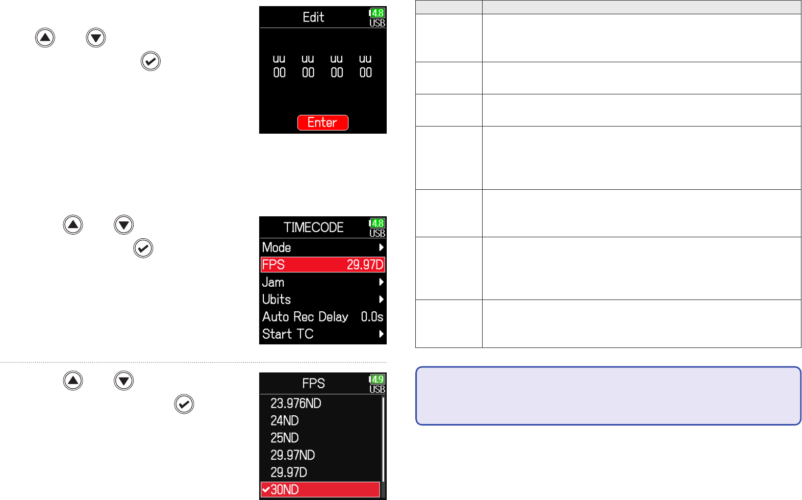
133
Setting Explanation
23.976ND
This is the most common frame rate used with HD cameras
and other high-denition video recording. The count is slower
than the actual time by 0.1%.
24ND
This is the standard frame rate used for recording lm. This is
also used with HD cameras.
25ND
This is the frame rate for PAL video. This is used for PAL video,
which is used in Europe and other regions.
29.97ND
This is a frame rate used for NTSC color video and HD cam-
eras. The count is slower than the actual time by 0.1%. This is
used for NTSC video, which is used in Japan, the United States
and other countries.
29.97D
This is an adjusted frame rate that uses a drop frame to make
NTSC match the actual time. This is used with video for broad-
cast that requires the actual time frame to be matched.
30ND
This is used to synchronize sound with lm that is being trans-
fered to NTSC video. This is the standard frame rate used for
black-and-white television in Japan, the United States and other
countries.
30D
This rate is used for special applications. This synchronizes
at 29.97 fps drop frame with lm sound to be transferred to
NTSC. The count is faster than the actual time by 0.1%.
NOTE
Frame rates must be set in advance to match on devices used for all video
and audio data.
6. When done setting, use
and to select
Enter, and press
.
■ Setting the frame rate for internal timecode
3. Use and to select
FPS, and press
.
4. Use and to select the
frame rate, and press
.

134
■ Jamming internal timecode
Timecode input through the TIMECODE IN jack is used to set internal
timecode
3. Use and to select
Jam, and press
.
4. Use and to select
Jam, and press
.
■ Restarting internal timecode with a specied value
3. Use and to select
Jam, and press
.
4. Use and to select
Restart, and press
.
5. Set the restart value.
Move cursor or change value:
Use and
Select parameter to edit:
Press

135
6. Use and to select
Restart, and press
.
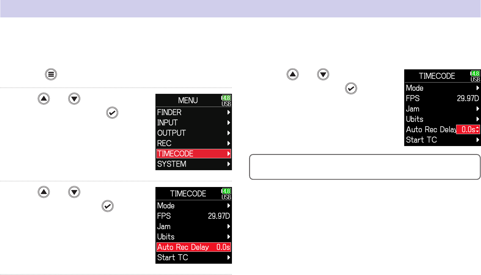
136
Setting the automatic timecode recording delay
1. Press .
2. Use and to select
TIMECODE, and press
.
3. Use and to select Auto
Rec Delay, and press
.
4. Use and to adjust
the time, and press
.
HINT
This can be set from 0.0 to 8.0 s.
If set to record automatically when external timecode is received, unnecessary recording could occur if timecode is received for a brief amount time.
In order to prevent this, the amount of time until recording starts after timecode is received can be set.

137
Setting timecode initialization used at startup
1. Press .
2. Use and to select
TIMECODE, and press
.
3. Use and to select
Start TC, and press
.
▶ Continue to one of the following procedures.
Setting how timecode is initialized at startup
(Start Timecode) ……………………………………………………………… P.137
Correcting timecode errors after the power has been
turned off…………………………………………………………………………… P.138
■ Setting how timecode is initialized at startup
4. Use and to select
Mode, and press
.
5. Use and to set
how timecode is initial-
ized, and press
.
Setting Explanation
Restart Time
When the
starts, the value set by Restart ( → P.134) is
used to jam the internal timecode.
RTC
When the
starts, its timecode is restored from the time-
code when the power was turned off and advanced by the
elapsed time using the Date/Time (RTC) setting ( →P.21).
Since RTC is less precise than internal timecode, discrepan-
cies will occur.
When the is turned off, the internal timecode stops, so the timecode is automatically initialized (jammed) during startup. The value that is used
for jamming at that time can be set.

138
■ Correcting timecode errors after the power has been
turned off
When the Start TC Mode is set to RTC, timecode precision will decrease
if the power is turned off. This function can be used to improve preci-
sion to almost 0.2 ppm even if the power is turned off.
4. Use and to select RTC
TC Calib, and press
.
5. Use and to select
Execute, and press
.
6. Calibration completes.
7. To cancel calibration, press
. Then, use and to
select Exit, and press
.
NOTE
• The
is calibrated before being shipped new from the factory.
• After calibrating once, the result will be retained.
• If the
is moved to and used in an extremely hot or cold location, time-
code precision could change slightly when the power is turned off. In such
cases, we recommend calibrating it again.
• Calibration is not possible when AIF with Rec is set to On.
• Calibration is only possible when Start TC Mode is set to RTC.
•
Calibration is not possible when the
is connected.

139
Using USB functions
Exchanging data with a computer
By connecting with a computer, data on the cards can be checked and copied.
■ Connecting
1. Press .
2. Use and to select
SYSTEM, and press
.
3. Use and to select
USB, and press
.
4. Use and to select SD
Card Reader, and press
.
5. Use a USB cable to connect the and the computer.
USB (Type-C)
NOTE
Use a USB cable that supports data transfer.

140
■ Disconnecting
1. Disconnect on the computer.
Windows:
Select with "Safely Remove Hardware”.
macOS:
Drag the icon to the Trash and drop it.
NOTE
Always conduct computer disconnection procedures before removing the
USB cable.
2. Disconnect the cable from the computer and the ,
and press
.

141
Using as an audio interface
■ Connecting
1. Press .
2. Use and to select
SYSTEM, and press
.
3. Use and to select
USB, and press
.
4. Use and to select Audio
Interface, and press
.
5. Use and to select
the mode and connected
device, and press
.
Setting Explanation
Stereo Mix
(PC/Mac)
This is a 2-in/2-out connection mode for Mac/Windows and
sends tracks 1–6 as a stereo mix.
Stereo Mix
(iPad)
This is a 2-in/2-out connection mode for iOS devices and sends
tracks 1–6 as a stereo mix.
Multi Track
(PC/Mac)
This is a 6-in/4-out connection mode for Mac/Windows and
sends tracks 1–6 as separate signals (cannot be used with
iOS devices).
A driver is necessary for use with Windows. Download the
driver from the ZOOM website (zoomcorp.com).
input signals can be input directly to a computer or iOS device, and playback signals on a computer or iOS device can be output from the .

142
6. Use a USB cable to connect the with the computer
or iOS device.
USB (Type-C)
NOTE
Use a USB cable that supports data transfer.
■ Disconnecting
1. Press .
2. Use and to select
Exit, and press
.
3. Use and to select
Exit, and press
.
4. Disconnect the cable from the computer or iOS device
and the
.

143
Using SD card recording and audio interface functions at the same time
In addition to SD card recording, a computer can also be used to record a backup.
4. Use and to select AIF
with Rec, and press
.
5. Use and to select
On, and press
.
6. Use a USB cable to connect the and the computer.
■ Connecting
1. Press .
2. Use and to select
SYSTEM, and press
.
3. Use and to select
USB, and press
.

144
NOTE
• AIF with Rec cannot be used with the following settings and functions.
- Sample rate settings other than 44.1/48 kHz
- SD card reader ( →P.139)
- Audio interface ( →P.141)
-
( →P.146)
• A driver is necessary for use with Windows. Download the driver from the
ZOOM website (zoomcorp.com).
• When AIF with Rec is set to On, the sample rate cannot be changed.
• When AIF with Rec is set to On, les with sample rates that differ from the
setting cannot be played.
• Set the input source to USB1–4 to monitor sound played back from the
computer ( →P.81) or select USB1–4 in the output routing ( →P.109,
P.112, P.113).
■ Disconnecting
1. Press .
2. Use and to select
Off, and press
.
3. Disconnect the cable from the computer and the .
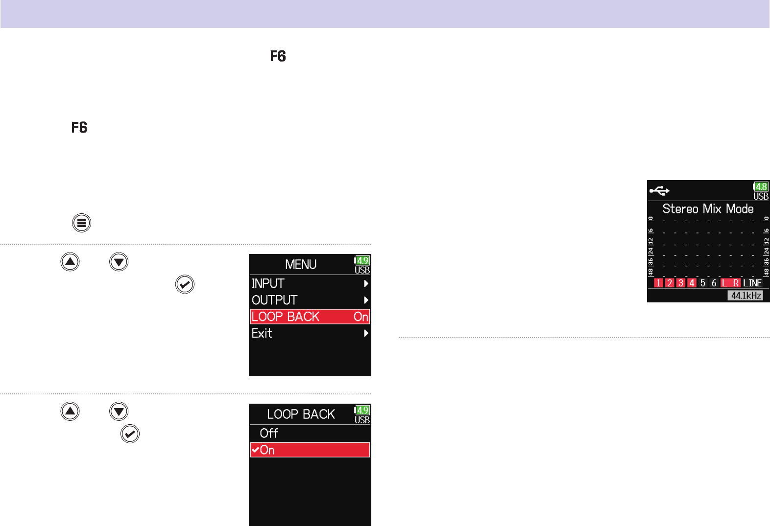
145
Audio interface settings
■ Setting loop back (Stereo Mix only)
This function mixes the playback sound from the computer or iOS de-
vice with the input and sends the mix back to the computer or iOS
device (loop back).
This function can be used to add narration to music played back from
the computer and to record the mix or stream it on the computer, for
example.
1. Press .
2. Use and to select
LOOP BACK, and press
.
3. Use and to select
On, and press
.
■ Mixing inputs
The mix balance of the inputs can be adjusted. Input signals will be
sent to the computer or iOS device using the balance settings made
here. When using a Stereo Mix setting, the mixed stereo signal will be
sent.
1. Open the mixer on the Home
Screen ( → P.13).
2. Adjust the parameter settings.
See "Adjusting the input signal monitoring balance" ( →P.79)
for how to change settings.
The following settings can be made when using the as an audio interface.

146
Using an FRC-8 as a controller
NOTE
An cannot be used when operating with AA batteries. When mul-
tiple power supplies are connected to an
, the power supply being used
will automatically change according to the remaining battery charge. When
it switches to AA batteries, connection with an
will be interrupted.
1. Press .
2. Use and to select
SYSTEM, and press
.
3. Use and to select
USB, and press
.
4. Use and to select
FRC-8, and press
.
5. Use and to select
Connect, and press
.
6. Use a USB cable to connect the and the .
7. Turn the power on.
When an is connected to the , it can be used to adjust settings, including trim, fader and pan.
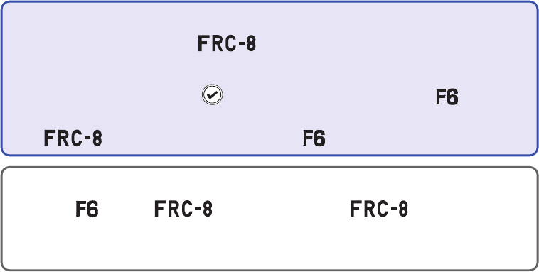
147
NOTE
•
When disconnecting the
, select Disconnect before unplugging
the USB cable
•
Select Connect and press
to supply bus power from the USB port.
When bus power is being supplied, do not connect any device other than
the
. Doing so could damage the or a connected device.
HINT
When an and an are connected, the will always oper-
ate on USB bus power. AA batteries and DC power supply connected to the
it are disabled.

148
Setting the type of keyboard connected to the FRC-8
A PC keyboard can be connected to the and used to input characters.
Set the type to use the PC keyboard connected to the .
1. Press .
2. Use and to select
SYSTEM, and press
.
3. Use and to select
USB, and press
.
4. Use and to select
FRC-8, and press
.
5. Use and to select Key-
board Type, and press
.

149
6. Use and to select
the type, and press
.
Setting Explanation
US This setting is for English-language keyboards.
JP This setting is for Japanese keyboards.

150
Setting user keys for the FRC-8
Functions can be assigned to the user keys.
4. Use and to select
FRC-8, and press
.
5. Use and to select
User Key, and press
.
1. Press .
2. Use and to select
SYSTEM, and press
.
3. Use and to select
USB, and press
.
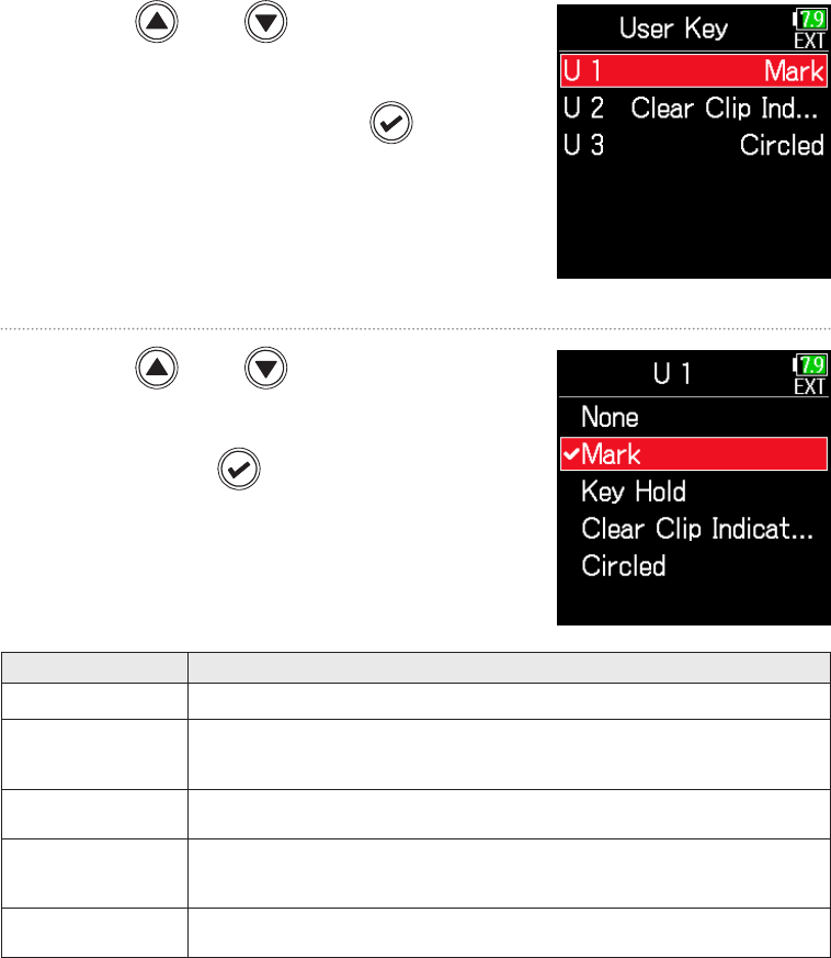
151
6. Use and to select
the key to which to assign
a function, and press
.
7. Use and to select
the function to assign,
and press
.
Setting Explanation
None No function is assigned.
Mark
Add marks to WAV format takes during recording and
playback.
Key Hold Use to disable the controls set with Key Hold Target.
Clear Clip
Indicator
Clear the level meter clipping indicators.
Circled Circle the currently selected take.

152
Setting the FRC-8 LED brightness
1. Press .
2. Use and to select
SYSTEM, and press
.
3. Use and to select
USB, and press
.
4. Use and to select
FRC-8, and press
.
5. Use and to select LED
Brightness, and press
.
The brightness of the LEDs on the front of the can be adjusted.

153
6. Use and to adjust the
brightness, and press
.
HINT
This can be set from 5 to 100.

154
Updating the FRC-8 rmware
1. See "Using an as a controller" ( → P.146), and
connect the
and the .
NOTE
Updating is not possible if the remaining power of the L battery is low. In
this case, use a charged L battery.
2. Copy the update le to the root directory on an SD card.
3. Load the SD card into the SD slot.
4. Press .
5. Use and to select
SYSTEM, and press
.
6. Use and to select
USB, and press
.
7. Use and to select
FRC-8, and press
.
▶ Continue to one of the following procedures.
Checking the rmware versions ………………………………………… P.155
Updating the rmware ………………………………………………………… P.155
The rmware version can be checked and updated to the latest version.
The latest update le can be downloaded from the ZOOM website (zoomcorp.com).

155
■ Updating the rmware
8. Use and to select
Firmware, and press
.
9. Use and to select
Update, and press
.
10. Use and to select
Update, and press
.
■ Checking the rmware versions
8. Use and to select
Firmware
, and press
.
9. Use and to select
Version, and press
.

156
NOTE
Do not turn the power off, remove an SD card or disconnect the USB
cable during an update. Doing so could cause the
to become
unstartable.
11. After the update completes,
turn the
power off.

157
Operating with an iOS device
■ Connecting with an iOS device
By connecting a ZOOM wireless adapter (e.g. BTA-1) and using the ded-
icated controller app, the can be operated from an iOS device.
NOTE
• The dedicated app must be installed on the iOS device beforehand. The
dedicated app can be downloaded from the App Store.
• See the manual for the app for procedures to set and operate it.
1. Remove the wireless adapter connector cover and con-
nect the wireless adapter.
2. Press .
3. Use and to select
SYSTEM, and press
.

158
4. Use and to select
Bluetooth, and press
.
5. Use and to select
F6 Control(iOS 9-12) or F6
Control, and press
.
Select this according to the version
used by the connected iOS device.
• Use F6 Control(iOS 9-12) with iOS
9 – 12
• Use F6 Control with iOS/iPadOS 13
or later
6. Use and to select
Connect, and press
.
7. Launch the dedicated
app on the iOS device.
If a list of Bluetooth devices appears
on F6 Control, connection will start
when you tap Device Name/ID.
When connection completes, “Con-
nected” will appear on the display.
HINT
• If a request for pairing appears from F6 Control, input the password
shown on the recorder.
• If connection is not successful, move the iOS device closer to the recorder
or move both to a place where nothing interferes with radio waves and
start F6 Control again. Conrm also that the Bluetooth function of the iOS
device can be used. If connection is still not possible, follow the instruc-
tions in the iOS device operation manual to unregister the
as a Blue-
tooth device on it. Then, repeat the procedures from the beginning.

159
■ Disconnecting from an iOS device
1. Press .
2. Use and to select
SYSTEM, and press
.
3. Use and to select
Bluetooth, and press
.
4. Use and to select
F6 Control(iOS 9-12) or F6
Control, and press
.
5. Use and to select Dis-
connect, and press
.
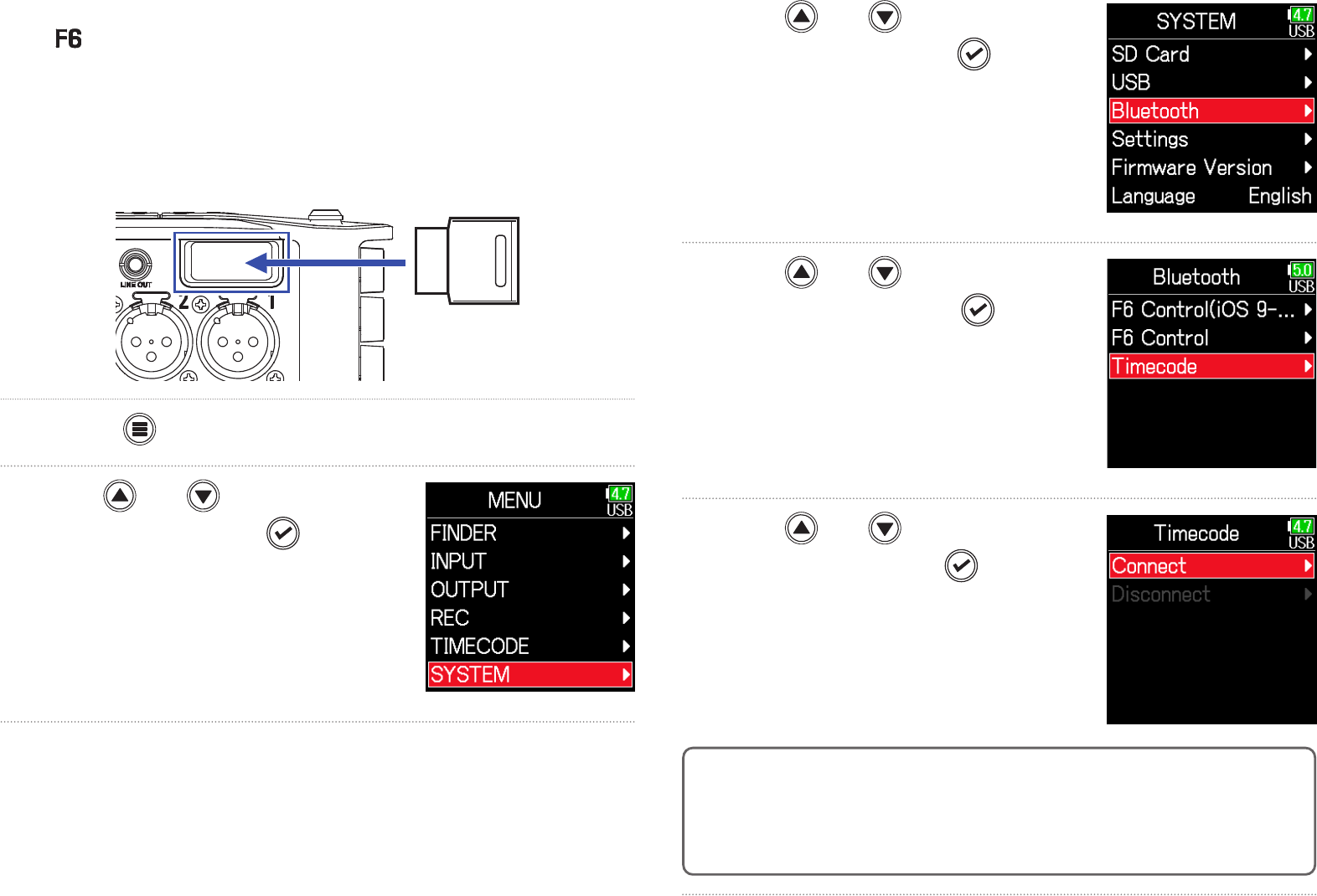
160
■ Connecting with an UltraSync BLUE
If the is connected to an UltraSync BLUE, it can receive timecode
from the UltraSync BLUE and add it to recording les.
1. Remove the wireless adapter connector cover and con-
nect the wireless adapter.
2. Press .
3. Use and to select
SYSTEM, and press
.
4. Use and to select
Bluetooth, and press
.
5. Use and to select
Timecode, and press
.
6. Use and to select
Connect, and press
.
Searching for the connected device
will begin and “Searching” will appear
on the display.
HINT
• Searching can be canceled by pressing any button.
• After canceling searching, it can be restarted by selecting Menu > Time-
code > Pair/Forget > Pair again.
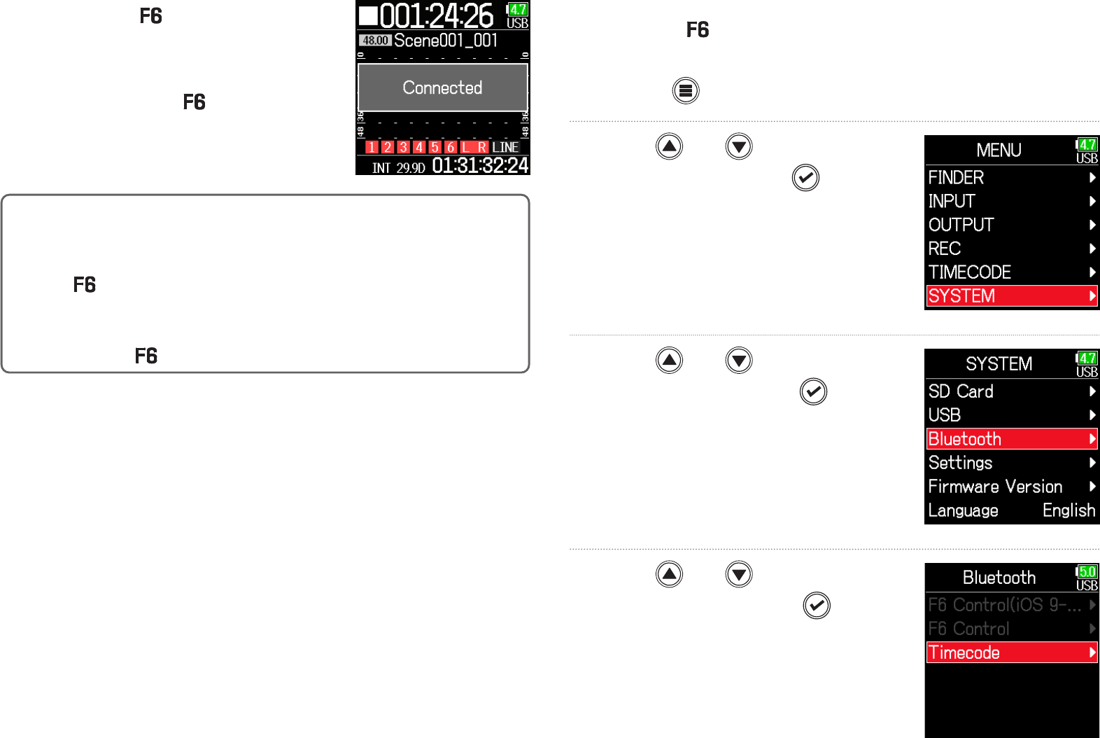
161
7. Select the as a connected
device on the UltraSync BLUE.
When pairing completes, “Connected”
will appear on the display.
HINT
• See the UltraSync BLUE manual for the procedures to select connected
devices.
•
Use the
and the UltraSync BLUE as close together as possible to make
communication more reliable.
• Even if communication with the UltraSync BLUE is interrupted, timecode
generated by the
will be added to recording les.
■ Disconnecting from an UltraSync BLUE
Disconnect the and the UltraSync BLUE to stop recording timecode
from it. Pairing information will be retained even when disconnected.
1. Press .
2. Use and to select
SYSTEM, and press
.
3. Use and to select
Bluetooth, and press
.
4. Use and to select
Timecode, and press
.

162
5. Use and to select Dis-
connect, and press
.
■ Connecting to a different UltraSync BLUE
To receive timecode from an UltraSync BLUE other than the one con-
nected to the , the pairing with the current UltraSync BLUE must be
removed, and pairing with the other UltraSync BLUE must be conduct-
ed.
1. Press .
2. Use and to select
TIMECODE, and press
.
3. Use and to select
Pair/Forget and press
.

163
4. Use and to select
Forget, and press
.
5. Use and to select
Pair, and press
.
Searching for the connected device
will begin and “Searching” will appear
on the display.
HINT
• Searching can be canceled by pressing any button.
• After canceling searching, it can be restarted by selecting Menu > Time-
code > Pair/Forget > Pair again.
6. Select as the connected device
on the other UltraSync BLUE.
When pairing completes, “Connected”
will appear on the display.
HINT
• See the UltraSync BLUE manual for the procedures to select connected
devices.
•
Use the
and the UltraSync BLUE as close together as possible to make
communication more reliable.
• Even if communication with the UltraSync BLUE is interrupted, timecode
generated by the
will be added to recording les.

164
Other settings
Setting the level meter peak hold time
1. Press .
2. Use and to select
SYSTEM, and press
.
3. Use and to select
Settings, and press
.
4. Use and to select
Display, and press
.
5. Use and to select Peak
Hold Time, and press
.
6. Use and to adjust the
peak hold time, and press
.

165
Setting the LED brightness
1. Press .
2. Use and to select
SYSTEM, and press
.
3. Use and to select
Settings, and press
.
4. Use and to select
Power Saving, and press
.
5. Use and to select LED
Brightness, and press
.
6. Use and to adjust the
brightness, and press
.
The brightness of the LEDs on the front of the can be set.

166
HINT
This can be set from 5 to 100.
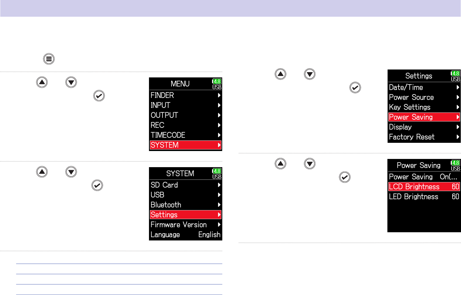
167
Making display settings
1. Press .
2. Use and to select
SYSTEM, and press
.
3. Use and to select
Settings, and press
.
▶ Continue to one of the following procedures.
Setting the display brightness …………………………………………… P.167
Changing the display backlight setting …………………………… P.168
Making the display easier to read under bright light ……… P.169
■ Setting the display brightness
4. Use and to select
Power Saving, and press
.
5. Use and to select LCD
Brightness, and press
.
Settings related to the display can be made.

168
5. Use and to select
Power Saving, and press
.
6. Use and to select
the setting, and press
.
Setting Explanation
Off
The backlight brightness does not change even after
time passes without use.
On (Low-Backlight) The backlight dims after time without use.
On (Backlight-Off) The backlight turns off after time without use.
6. Use and to adjust the
brightness, and press
.
HINT
This can be set from 5 to 100.
■ Changing the display backlight setting
The display backlight can be set to dim when 30 seconds pass without
use.
4. Use and to select
Power Saving, and press
.

169
■ Making the display easier to read under bright light
The display can be set to be easier to read in bright environments in-
cluding in sunlight.
4. Use and to select
Display, and press
.
5. Use and to select Out-
door Mode, and press
.
6. Use and to select
On, and press
.

170
Setting how marks are added manually
1. Press .
2. Use and to select
SYSTEM, and press
.
3. Use and to select
Settings, and press
.
4. Use and to select Key
Settings, and press
.
5. Use and to select PLAY
Key Option, and press
.
▶ Continue to one of the following procedures.
Setting how marks are added when recording ………………… P.171
Setting how marks are added when playing …………………… P.171
How marks are added when is pressed while recording or playing back a WAV format le can be set.

171
■ Setting how marks are added when playing
6. Use and to select
Playing, and press
.
7. Use and to select how
marks are added, and press
.
Setting Explanation
Pause Only
Pressing
will pause without adding a mark.
Pause & Mark
Pressing
will pause and add a mark.
Mark Only
Pressing
will add a mark without pausing.
■ Setting how marks are added when recording
6. Use and to select
Recording, and press
.
7. Use and to select how
marks are added, and press
.
Setting Explanation
Pause Only
Pressing
will pause without adding a mark.
Pause & Mark
Pressing
will pause and add a mark.
Mark Only
Pressing
will add a mark without pausing.

172
Setting the buttons held
1. Press .
2. Use and to select
SYSTEM, and press
.
3. Use and to select
Settings, and press
.
4. Use and to select Key
Settings, and press
.
5. Use and to select Key
Hold Target, and press
.
6. Use and to select the
keys to be held, and press
.
Use the hold function to prevent misoperation during recording. Press and hold to enable and disable the hold function.
Follow these instructions to set which keys are disabled by the hold function.

173
HINT
Track Knobs 1–6, MENU, ENTER, UP, DOWN, PLAY, REC, STOP, HP Volume
Push and HP Volume Turn can be selected.
7. Press .
HINT
•
Even when hold is on for HP Volume Push, pressing and holding
will turn the hold function off.
• Operation using the
and F6 Control is possible even when the hold
function is on.

174
Other functions
Checking SD card information
The size and open space of SD cards can be checked.
1. Press .
2. Use and to select
SYSTEM, and press
.
3. Use and to select
SD Card, and press
.
4. Use and to select
Information, and press
.
■ SD card information
Open space
Size
Remaining
recording time

175
Testing SD card performance
SD cards can be tested to conrm whether they can be used with the . A basic test can be done quickly, while a full test examines the entire SD
card.
1. Press .
2. Use and to select
SYSTEM, and press
.
3. Use and to select
SD Card, and press
.
4. Use and to select Per-
formance Test, and press
.
▶ Continue to one of the following procedures.
Conducting a quick test ……………………………………………………… P.176
Conducting a full test ………………………………………………………… P.177
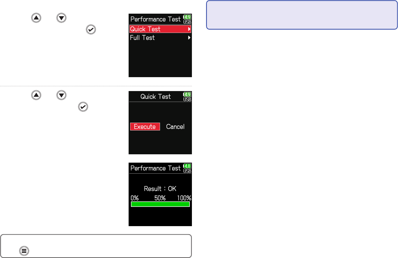
176
■ Conducting a quick test
5. Use and to select
Quick Test, and press
.
6. Use and to select
Execute, and press
.
The card performance test will start.
The test should take about 30 seconds.
The test completes.
The result of the evaluation will be
shown.
HINT
Press to stop the test.
NOTE
Even if a performance test result is "OK", there is no guarantee that writing
errors will not occur. This information is just to provide guidance.

177
■ Conducting a full test
5. Use and to select
Full Test, and press
.
The amount of time required for the
full test will be shown.
6. Use and to select
Execute, and press
.
The test completes.
The result of the evaluation will be
shown. If the access rate MAX reach-
es 100%, the card will fail (NG).
HINT
Press to stop the test.
NOTE
Even if a performance test result is "OK", there is no guarantee that writing
errors will not occur. This information is just to provide guidance.
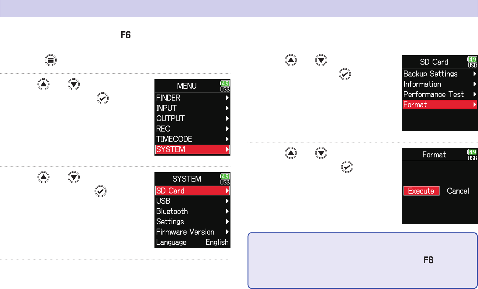
178
Formatting SD cards
1. Press .
2. Use and to select
SYSTEM, and press
.
3. Use and to select
SD Card, and press
.
4. Use and to select
Format, and press
.
5. Use and to select
Execute, and press
.
NOTE
• Before using SD cards that have just been purchased or that have been
formatted on a computer, they must be formatted by the
.
• Be aware that all data previously saved on the SD card will be deleted
when it is formatted.
Formatting SD cards for use with the .

179
Checking the F6 Shortcut List
1. Press .
2. Use and to select
SYSTEM, and press
.
3. Use and to select
Settings, and press
.
4. Use and to select Key
Settings, and press
.
5. Use and to select
Shortcut List, and press
.
The has a shortcut feature that allows quick access to various functions.
See the "List of shortcuts" ( →P.192) to check the shortcut functions.

180
Backing up and loading F6 settings
settings can be backed up to and loaded from SD cards.
1. Press .
2. Use and to select
SYSTEM, and press
.
3. Use and to select
SD Card, and press
.
4. Use and to select
Backup Settings, and press
.
▶ Continue to one of the following procedures.
Backing up …………………………………………………………………………… P.181
Loading ………………………………………………………………………………… P.181

181
■ Backing up
This saves a backup le to the "F6_SETTINGS" folder in the root direc-
tory of the SD card.
5. Use and to select
Backup, and press
.
6. Edit the name of the le saved.
See "Character input screen"
( →P.14) for how to input
characters.
HINT
The extension of the saved backup le is ".ZSF".
■ Loading
Backup les that are saved in the "F6_SETTINGS" folder in the root di-
rectory of the SD card can be loaded.
5. Use and to select
Load/Delete, and press
.
6. Use and to select the
le to load, and press
.
HINT
•
Press and hold
to delete a le.
• Deleting a le will completely erase its data.

182
7. Use and to select
Execute, and press
.
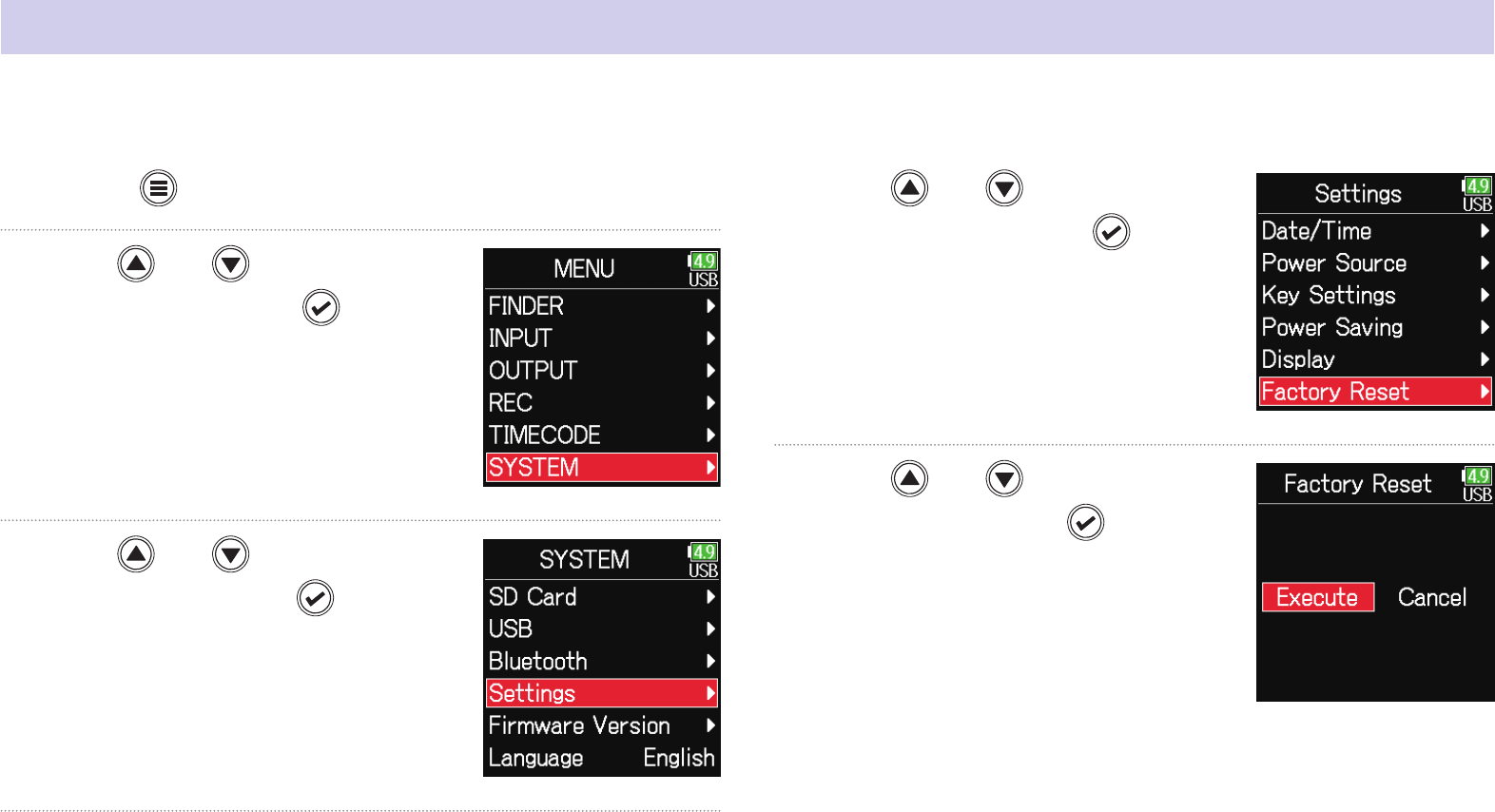
183
Restoring default setting values
1. Press .
2. Use and to select
SYSTEM, and press
.
3. Use and to select
Settings, and press
.
4. Use and to select Fac-
tory Reset, and press
.
5. Use and to select
Execute, and press
.
The settings will be reset and the
power will automatically turn off.
The factory default settings can be restored.

184
Checking the rmware version
1. Press .
2. Use and to select
SYSTEM, and press
.
3. Use and to select Firm-
ware Version, and press
.
Firmware versions can be checked.

185
Updating the rmware
1. Install new batteries in the or connect the dedicated
AC adapter to the USB connector.
NOTE
Upgrading is not possible if the remaining battery power is low. In this
case, replace the batteries with new ones or use the dedicated adapter.
2. Copy the update le to the root directory on an SD card.
3. Load the SD card into the card slot, and turn the power
on while pressing
.
4. Use and to select
Update, and press
.
NOTE
Do not turn the power off or remove the SD card during the update. Doing
so could cause the
to become unstartable.
5. After the update com-
pletes, turn the power off.
NOTE
In the unlikely event that a rmware update should fail while in progress,
conduct the procedures from the beginning to update the rmware again.
The rmware can be updated to the latest versions.
The latest update le can be downloaded from the ZOOM website (zoomcorp.com).

186
■ Recording/playback trouble
◆
There is no sound or output is very quiet
• Check the connections to the monitoring system and its volume setting.
• Conrm that the volume of the
is not too low. (
→
P.36)
◆
Sound from connected equipment or inputs cannot be
heard or is very quiet
• Check the input level settings. (
→
P.28)
• If a CD player or other device is connected to an input jack, raise the out-
put level of that device.
• Check the input signal monitoring settings. (
→
P.79)
• Check the phantom power and plug-in power settings. (
→ P. 81,
P.95)
• Check the headphone and line output routing settings. (
→
P.109,
P.112, P.113)
◆
Recording is not possible
• Conrm that the status indicators are lit red.
• Conrm that the SD card has open space. (
→
P.174)
• Conrm that an SD card is loaded properly in a card slot.
• If “Card Protected!” appears on the display, the SD card write-protection
is enabled. Slide the lock switch on the SD card to disable write-protec-
tion.
◆
The recorded sound cannot be heard or is very quiet
• Conrm that the volume levels of the tracks are not too low. (
→
P.55)
• Conrm that the status indicators are lit green during playback.
■ Other trouble
◆
Computer does not recognize it even though it is connect-
ed to the USB port.
• Conrm that the operating system is compatible. (
→
P.139)
• The operation mode must be set on the
to allow the computer to rec-
ognize the
. (
→
P.141)
Appendix
Troubleshooting
If you think that the is operating strangely, check the following items rst.
187
◆
Battery operation time is short
Making the following settings could increase the battery operation time.
• Set the power supply used correctly. (
→
P.23)
• Turn unnecessary tracks off. (
→
P.27)
• Disconnect unneeded devices that are plugged into the HEADPHONE,
LINE OUT or TIMECODE IN/OUT jacks, for example.
• Set the phantom power voltage to 24V. (
→
P.96)
• Disable phantom power during playback. (
→
P.96)
• Turn timecode off if not using it. (
→
P.128)
• Reduce the LED brightness.(
→
P.165)
• Reduce the LCD brightness.(
→
P.167)
• Set the display to dim when not used for some time. (
→
P.168)
• Reduce the sampling rate used to record les. (
→
P.30).
• Due to their characteristics, using nickel metal hydride batteries (espe-
cially high-capacity ones) or lithium batteries should enable longer use
than alkaline batteries when power consumption is high.
◆
The date and time reset frequently
• Turn the power on to charge the built-in rechargeable battery used to re-
tain the date and time.

188
■ Metadata contained in WAV le BEXT chunks
Tag Explanation Remarks
zSPEED= Frame rate MENU > TIMECODE > FPS
zTAKE= Take number
zUBITS= Ubits MENU > TIMECODE > Ubits
zSCENE= Scene Name
MENU > REC > Metadata > Scene Name > Mode
MENU > REC > Metadata > Scene Name > User Name
MENU > FINDER > Option > Metadata Edit > Scene > Scene/Take
MENU > FINDER > Option > Rename
zTAPE=
Name of recording destination
folder
MENU > FINDER (recording destination folder name)
MENU > FINDER > Option > Metadata Edit > Tape Name
zCIRCLED= Circled take MENU > FINDER > Option > Metadata Edit > Circle
zTRK1= Left track name
Track names are written as follows.
TRK1=TrL, TRK2=TrR, TRK3=Tr1, TRK4=Tr2 … TRK8=Tr6
zTRK2= Right track name
zTRK3= Track 1 name
zTRK4= Track 2 name
zTRK5= Track 3 name
zTRK6= Track 4 name
zTRK7= Track 5 name
zTRK8= Track 6 name
zNOTE= Take note
MENU > Metadata > Note
MENU > FINDER > Option > Metadata Edit > Note
Metadata list

189
■ Metadata contained in WAV le iXML chunks
iXML master tag iXML sub tag Written
Read
Remarks
<PROJECT>
○ ○
MENU > FINDER (folder name at top SD card level)
MENU > FINDER > Option > Metadata Edit > Project Name
<SCENE>
○ ○
MENU > REC > Metadata > Scene Name > Mode
MENU > REC > Metadata > Scene Name > User Name
MENU > FINDER > Option > Metadata Edit > Scene >
Scene/Take
MENU > FINDER > Option > Rename
<TAKE>
○ ○
MENU > FINDER > Option > Metadata Edit > Take
MENU > FINDER > Option > Rename
<TAPE>
○ ○
MENU > FINDER (recording destination folder name)
MENU > FINDER > Option > Metadata Edit > Folder (Tape)
Name
<CIRCLED>
○ ○
MENU > FINDER > Option > Metadata Edit > Circle
<WILD TRACK> × ×
<FALSE START> × ×
<NO GOOD> × ×
<FILE_UID>
○
×
<UBITS>
○
× MENU > TIMECODE > Timecode > Ubits
<NOTE>
○ ○
MENU > REC > Metadata > Note
MENU > FINDER > Option > Metadata Edit > Note
<BEXT> × ×
<USER> × ×

190
iXML master tag iXML sub tag Written
Read
Remarks
<SPEED>
<SPEED> <NOTE>
○
×
<SPEED> <MASTER_SPEED>
○ ○
MENU > TIMECODE > FPS
<SPEED> <CURRENT_SPEED>
○
× MENU > TIMECODE > FPS
<SPEED> <TIMECODE_RATE>
○
× MENU > TIMECODE > FPS
<SPEED> <TIMECODE_FLAG>
○
× MENU > TIMECODE > FPS
<SPEED> <FILE_SAMPLE_RATE>
○
× MENU > REC > Sample Rate
<SPEED> <AUDIO_BIT_DEPTH>
○
× MENU > REC > Mode
<SPEED> <DIGITIZER_SAMPLE_RATE>
○
× MENU > REC > Sample Rate
<SPEED> <TIMESTAMP_SAMPLES_SINCE_MIDNIGHT_HI>
○
×
<SPEED> <TIMESTAMP_SAMPLES_SINCE_MIDNIGHT_LO>
○
×
<SPEED> <TIMESTAMP_SAMPLE_RATE>
○
× MENU > REC > Sample Rate
iXML master tag iXML sub tag Written
Read
Remarks
<SYNC_POINT_LIST>
<SYNC_POINT> <SYNC_POINT_TYPE> × ×
<SYNC_POINT> <SYNC_POINT_FUNCTION> × ×
<SYNC_POINT> <SYNC_POINT_COMMENT> × ×
<SYNC_POINT> <SYNC_POINT_LOW> × ×
<SYNC_POINT> <SYNC_POINT_HIGH> × ×
<SYNC_POINT> <SYNC_POINT_EVENT_DURATION> × ×
iXML master tag iXML sub tag Written
Read
Remarks
<HISTORY>
<HISTORY> <ORIGINAL_FILENAME>
○
×
<HISTORY> <PARENT_FILENAME> × ×
<HISTORY> <PARENT_UID> × ×

191
iXML master tag iXML sub tag Written
Read
Remarks
<FILE_SET>
<FILE_SET> <TOTAL_FILES>
○
×
<FILE_SET> <FAMILY_UID>
○
×
<FILE_SET> <FAMILY_NAME> × ×
<FILE_SET> <FILE_SET_START_TIME_HI> × ×
<FILE_SET> <FILE_SET_START_TIME_LO> × ×
<FILE_SET> <FILE_SET_INDEX>
○
×
iXML master tag iXML sub tag Written
Read
Remarks
<TRACK_LIST>
<TRACK_LIST> <TRACK_COUNT>
○
×
<TRACK> <CHANNEL_INDEX>
○
×
<TRACK> <INTERLEAVE_INDEX>
○
×
<TRACK> <NAME>
○ ○
MENU > REC > Metadata > Track Name
MENU > FINDER > Option > Metadata Edit > Track Name
<TRACK> <FUNCTION> × ×
○ = YES × = NO
■ Metadata and ID3 elds contained in MP3 les
Metadata ID3 eld Format
Timecode Artist Name TC=[HH:MM:SS:FF]
Scene name, take number Track Title SC=[scene name] TK=[take number]
Frame rate, le length (time) Album Title FR=[frame rate] D=[le length (time)]

192
■ Home Screen
Operation from
Operation from
Explanation
Press and hold
Press and hold MENU Show the name that will be given to the next take recorded. Example: Scene001_002
+
MENU + ENCODER press Advance the scene number by 1 (when the Home Screen is open).
+
MENU + FF
The number given to the next recorded take can be increased or decreased by one when the Home
Screen is open.
+
MENU + REW Move the previously recorded take to the FALSE TAKE folder (when the Home Screen is open).
+
ENCODER press + FF Open L/R track fader and line output level setting screen.
+
ENCODER press + REW Click the level meter clipping indicators.
Press and hold
Press and hold FF Circle the currently selected take.
■ Input link, trim link and routing screens
Operation from
Operation from
Explanation
+
− Move the cursor up.
+
− Move the cursor down.
■ All screens
Operation from
Operation from
Explanation
Press and hold
– Disable controls set with "Key Hold".
List of shortcuts

193
Block diagrams
■ Input and output signal ow (Linear and Dual modes)
The Input Limiter is disabled
when in Dual mode.

194
■ Input and output signal ow (Float mode)
The Input Limiter is disabled when in Dual mode.
Converter“Rec Level” adjusts the recording levels of each input,
and “ Tr1-6 Fader” adjusts the levels of each input sent to the
LR track. Both types of levels can be adjusted with . The
behavior of the “Rec Level” and “Tr1-6 Fader” when is
operated can be set to one of the following two options
usingMenu > INPUT > Track Knob.
■ Reference Level (default)
Operating when recording is stopped adjusts the “Rec
Level”. When recording starts, the “Rec Level” becomes fixed at
the levels set at the time recording started. During recording,
adjust the “Tr1-6 Faders”.
■ Rec Level
always adjust the “Rec Level” both during recording and
when recording is stopped.The “Tr1-6 Faders” are bypassed.

195
■ Input and output signal ow (Audio Interface Stereo Mix)
,QSXW
,QSXW
,QSXW
,QSXW
7ULP
+3)
,QSXW/LPLWHU
3KDVH , QYHUW
066WHUHR
,QSXW'HOD\
7U)DGHU
3&
$XWR0L[
/
5
/5)DGHU
3DQ
3&
&K
&K
/RRS%DFN
$PELVRQLFV
%IRUPDW
&RQYHUWHU
$PELVRQLFV
67HUHR
&RQYHUWHU
/,1(287
+($'3+21(
287
287387
2XWSXW'HOD\ +39ROXPH
6ODWH7RQH
2XWSXW/LPLWHU
/LQH2XW/HYHO
+3$OHUW7RQH
5R XWLQJ
/
5
/
5
3RVWIDGHU
3UHIDGHU
入出力信号ブロック図オーディオ,) ステレオミックス

■ Input and output signal ow (Audio Interface Multi Track)
,QSXW
,QSXW
,QSXW
,QSXW
7ULP
+3)
,QSXW/LPLWHU
3KDVH , QYHU W
066WHUHR
,QSXW'HOD\
7U)DGHU
3&
/,1(287
+($'3+21(
287
287387
$XWR0L[
/
5
2XWSXW'HOD\ +39R OXPH
6ODWH7RQH
2XWSXW/LPLWHU
/LQH2XW/HYHO
+3$OHUW7RQH
/5)DGHU
3DQ
5R XWLQJ
7UDFN
7UDFN
7UDFN
7UDFN
7UDFN/
7UDFN5
3RVWIDGHU
3UHIDGHU
$PELVRQLFV
%IRUPDW
&RQYHUWHU
/
5
/
5
$PELVRQLFV
6WHUHR
&RQYHUWHU
3&
&K
&K
入出力信号ブロック図オーディオ,) マルチトラック
196

197
L, R
Slate
Tone
φ
φ
φ
φ
φ
φ
■ Detailed block diagram (Linear & Dual modes)

198
L, R
Slate
Tone
φ
φ
φ
φ
φ
φ
■ Detailed block diagram (Float mode)
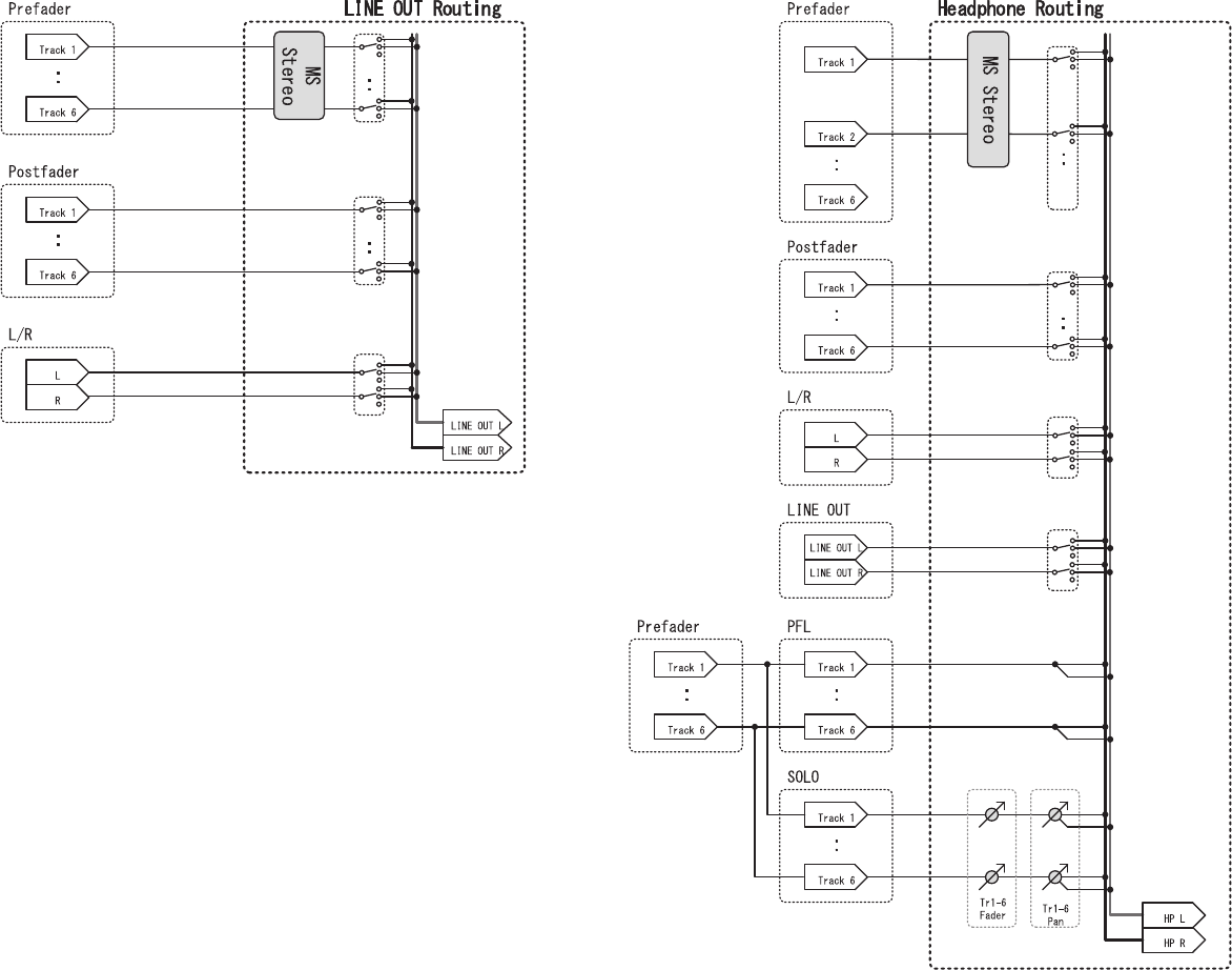
199
■ Detailed block diagram (Routing)

200
Recording media SD cards, SDHC cards, SDXC cards (that conform to standards)
Inputs Inputs 1–6 Connectors XLR jack (pin 2 hot)
Input (mic) Input gain +12 dB – +75 dB
Input impedance 3 kΩ
Maximum input level +4 dBu
Input (line) Input gain -8 dB – +55 dB
Input impedance 5 kΩ
Maximum input level +24 dBu
Phantom power +24/+48V 10mA maximum for each channel
Equivalent input noise −127 dBu or less (A-weighted, +75 dB input gain, 150Ω input)
Outputs Line output Connectors 3.5 mm stereo mini unbalanced output
Output impedance 100 Ω or less
Reference output level –10 dBV, 1 kHz, 10kΩ load
Maximum output level +10 dBV, 1 kHz, 10kΩ load
D/A dynamic range 95 dB typ (–60dBFS input, A-weighted)
Headphone output Connector 3.5 mm stereo mini unbalanced output
Output impedance 15 Ω or less
Maximum output level 100 mW + 100 mW (32Ω load)
D/A dynamic range 108 dB typ (−60dBFS input, A-weighted)
Recording formats When WAV selected
Supported formats 44.1/47.952/48/48.048/88.2/96/192 kHz, 16/24-bit/32-bit oat, mono/stereo/2-8ch poly, BWF/iXML supported
Maximum simultaneous recording tracks 14 (6 inputs x 2 (Liner and Floating) + LR mix)
6 (6 inputs (Liner or Floating) at 192kHz sampling rate)
When MP3 selected
Supported formats 128/192/320kbps, 44.1/48 kHz, ID3v1 tags supported
Maximum simultaneous recording tracks 2
Recording time Using a 32 GB card
30:46:00 (48 kHz/24-bit stereo WAV)
7:41:00 (192 kHz/24-bit stereo WAV)
Timecode Connector 3.5 mm stereo mini (Tip: IN, Ring: OUT)
Modes Off, Int Free Run, Int Record Run, Int RTC Run, Ext, Ext Auto Rec (audio clock can be synchronized to timecode)
Frame rates 23.976 ND, 24 ND, 25 ND, 29.97 ND, 29.97 D, 30 ND, 30 D
Precision ±0.2 ppm
Allowed input level 0.2 – 5.0 Vpp
Allowed input impedance 4.6 kΩ
Output level 3.3 Vpp
Output impedance 50 Ω or less
Power AC adapter (ZOOM AD-17): DC 5V/1A (supports USB bus power)
Sony® L-Series battery
4 AA batteries (alkaline, lithium or rechargeable NiMH batteries)
Specications

201
Continuous recording
time
48 kHz/16-bit 2ch recording to SD card
(LINE OUT off, TIMECODE off, LED/LCD Brightness 5, headphones into 32Ω load, PHANTOM off)
Alkaline batteries 7.5 hours or more
NiMH batteries
(2500 mAh)
10.5 hours or more
Lithium batteries 16.5 hours or more
48 kHz/24-bit 6ch recording to SD card
(LINE OUT off, TIMECODE off, LED/LCD Brightness 5, headphones into 32Ω load, PHANTOM off)
Alkaline batteries 4.5 hours or more
NiMH batteries
(2500 mAh)
7 hours or more
Lithium batteries 10.5 hours or more
192 kHz/24-bit 6ch recording to SD card
(LINE OUT on, TIME CODE set to Int Free Run, LED/LCD Brightness 60, headphones into 32Ω load, PHANTOM at 48 V)
Alkaline batteries about 0.5 hours
NiMH batteries (2500 mAh) 1.0 hours or more
Lithium batteries 3.0 hours or more
Display 1.54" full-color LCD (240 × 240)
USB Mass storage operation
Class USB 2.0 High Speed
Multitrack audio interface operation (driver required for Windows, no driver required for macOS)
Class USB 2.0 High Speed
Specications Sampling rate 44.1/48/88.2/96 kHz
Bit Rate 16/24-bit
Channels 6 in/4 out
Stereo mix audio interface operation (no driver required)
Class USB 2.0 Full Speed
Specications Sampling rate 44.1/48 kHz
Bit Rate 16-bit
Channels 2 in/2 out
Note: iOS device audio interface operation supported (stereo mode only)
AIF with Rec operation (driver required for Windows, no driver required for macOS)
Class USB 2.0 High Speed
Specications Sampling rate 44.1/48 kHz
Bit Rate 16/24-bit
Channels 8 in/4 out
Note: Use a USB cable that supports data transfer. USB bus power is supported.
Power consumption Main unit only 1 W
Using L battery with FRC-8 connected 10 W
External dimensions 100 mm (W) × 119.8 mm (D) × 62.9 mm (H)
Weight 520 g