
Purdue University
Purdue e-Pubs
International Refrigeration and Air Conditioning
Conference
School of Mechanical Engineering
2010
Experimental Studies to Evaluate the Use of Metal
Foams in Highly Compact Air-Cooling Heat
Exchangers
Kashif Nawaz
University of Illinois at Urbana Champaign
Jassie Bock
University of Illinois at Urbana Champaign
Zhengshu Dai
Institute of Reigeration and Cryogenics
Anthony M. Jacobi
University of Illinois at Urbana Champaign
Follow this and additional works at: h>p://docs.lib.purdue.edu/iracc
=is document has been made available through Purdue e-Pubs, a service of the Purdue University Libraries. Please contact epubs@purdue.edu for
additional information.
Complete proceedings may be acquired in print and on CD-ROM directly from the Ray W. Herrick Laboratories at h>ps://engineering.purdue.edu/
Herrick/Events/orderlit.html
Nawaz, Kashif; Bock, Jassie; Dai, Zhengshu; and Jacobi, Anthony M., "Experimental Studies to Evaluate the Use of Metal Foams in
Highly Compact Air-Cooling Heat Exchangers" (2010). International Reigeration and Air Conditioning Conference. Paper 1150.
h>p://docs.lib.purdue.edu/iracc/1150
2502, Page 1
International Refrigeration and Air Conditioning Conference at Purdue, July 12-15, 2010
Experimental Studies to Evaluate the Use of Metal Foams in Highly Compact
Air-Cooling Heat Exchangers
K. Nawaz1, J. Bock1, Z. Dai2, and A. Jacobi1
1Department of Mechanical Science and Engineering, University of Illinois, Urbana,
Illinois, U.S.A.
2Institute of Refrigeration and Cryogenics, Zhejiang University, Hangzhou, Zhejiang,
China
Abstract:
open-cell aluminum foam is considered as a highly compact replacement for
conventional fins in brazed aluminum heat exchangers. The experimental data needed
to for evaluation are obtained through wind-tunnel experiments. Using a closed-loop
wind tunnel, heat transfer and pressure drop measurements are undertaken, and the
results are characterized as Colburn j-factor and friction factor for geometric
configurations of foam and flat tubes that mimic current multi-louver, microchannel
geometries. The data obtained in the wind-tunnel are used to evaluate the potential for
using metal foam (of varying porosity) as a replacement to conventional fins for a
range of configurations and operating conditions typical for air-cooling applications.
Finally, we comment on some of the challenges that must be met for the adoption of
this technology in air-cooling systems.
Introduction:
Metal foams are porous media with low density and novel thermal, mechanical,
electrical, and acoustic properties [1]. They can be categorized as open-cell or closed-
cell foams, but only open-cell metal foams appear to have promise for constructing
heat exchangers. Open-cell metal foams have high specific surface area, relatively
high thermal conductivity, and a tortuous flow path to promote mixing. Metal foam
have been studies by a number of researchers for thermal applications; some were
focused on metal-foam heat exchangers (and heat sinks), and many others
investigated the basic thermal transport properties of metal foams. The basic
properties of the metal foams include the effective thermal conductivity, permeability,
and inertial coefficient. Calmidi and Mahajan [2] investigated the effective thermal
conductivity of high-porosity fibrous metal foams experimentally. An empirical
correlation was developed and a theoretical model was derived. The model
predictions agreed closely with the experimental data and were used for the evaluation
of metal foams as possible candidates for heat sinks in electronics cooling
applications. Boomsma and Poulikakos [3] see also [4] developed a one-dimensional
heat conduction model for use with open-cell metal foams, based on idealized three-
International Refrigeration and Air Conditioning Conference at Purdue, July 12-15, 2010
dimensional cell geometry of the foam. Their model showed that the fluid-phase
conductivity has a relatively small effect on the effective thermal conductivity, and
the overall effective thermal conductivity of the metal foam is controlled by the solid-
phase conductivity to a large extent. Bhattacharya et al. [5] conducted research on the
determination of the effective thermal conductivity, permeability, and inertial
coefficient of highly porous metal foams. A theoretical model was formulated and the
analysis showed that the effective thermal conductivity depends strongly on the
porosity and the ratio of the cross-sections of the fiber and the intersection, but no
systematic dependence on pore density was found. Fluid flow experiments were
conducted and the results showed that permeability increases with pore diameter and
porosity of the medium, and the inertial coefficient depends only on porosity. They
proposed a theoretical model for predicting inertial coefficient and a modified
permeability model; the models were shown to agree with experimental results.
Tadrist et al. [6] discussed the characteristics of randomly stacked fibers and metallic
foams and analyzed the transport properties for both materials.
Convection in porous media has been widely investigated, but most studies
focused on packed beds and granular materials with low porosities in the range 0.3-
0.6. The porosity of open-cell metal foams is much higher (Ȝ>0.90), and only during
the past decade has convection in high-porosity metal foams started to receive
attention. Calmidi and Mahajan [7] investigated forced convection in high-porosity
metal foams experimentally and numerically. Experimental results showed that the
transport enhancing effect of thermal dispersion is extremely low with foam-air
combinations, but for foam-water combinations it can be very high. In the numerical
study, a thermal non-equilibrium model was used and a Nusselt number correlation
was determined. Zhao et al. [8] studied natural convection and its effect on overall
heat transfer in highly porous open-cell FeCrAlY foams experimentally and
numerically. Experimental results showed that natural convection is significant in
metal foams due to the high porosity and inter-connected open cells. Numerical
calculations showed that the so-called non-equilibrium effect (the metal and fluid
being at different temperatures) cannot be neglected and hence a two-equation energy
model should be used instead of one-equation model for convection in metal foams.
Hetsroni et al. [9] studied natural convection heat transfer in metal foam strips with
internal heat generation by experiments. Infrared images on both the surface and the
inner region of the metal foam were analyzed, and the non-equilibrium temperature
distribution was estimated. The result indicated that the non-equilibrium effect is
significant.
Some studies have focused on metal-foam convective heat transfer devices.
Boomsma et al. [10] studied an open-cell aluminum foam heat sink for electronics
cooling applications. They found that compressed aluminum foams performed well,
offering a significant improvement in the efficiency over several commercially
available heat exchangers. They also found the metal foam can decrease the thermal
resistance to nearly half that of currently used heat exchangers in the same
application. Zhao et al. [11] and Lu et al. [12] analyzed forced convection heat
transfer performance in high-porosity, open-cell, metal-foam-filled heat exchanger
2502, Page 2
International Refrigeration and Air Conditioning Conference at Purdue, July 12-15, 2010
tubes and metal-foam-filled pipes using the Brinkman-extended Darcy momentum
model and the two-equation heat transfer model for porous media. The results showed
that, compared to conventional, finned-tube heat exchangers, the heat exchangers with
metal-foam-filled tubes have better heat transfer performance, and the metal-foam-
filled pipes have much better thermal performance than a plain tube, but at the
expense of higher pressure drop. Mahjoob and Vafai [13] have discussed the effects
of micro-structural metal foam properties on heat exchanger performance, and they
categorized and investigated the extant correlations for flow and thermal transport in
metal-foam heat exchangers. Tube and channel metal-foam heat exchangers were
used to evaluate thermal-hydraulic performance, and the results showed a
considerable improvement in performance by inserting the metal foam. Ejlali et al.
[14] numerically investigated the fluid flow and heat transfer of an air-cooled metal-
foam heat sink under a high speed laminar jet confined by two parallel walls at
Reynolds numbers from 600 to 1000. They compared the performance of the metal-
foam heat sink to that of conventional finned design and found that the heat removal
rate can be greatly improved without additional cost. Dai et al. [15] presented the
comparison of metal-foam heat exchangers to louver-fin heat exchangers based on
theȜ-N
TU
method; the results showed that with the same thermal-hydraulic
performance, the metal-foam heat exchanger can be lighter and smaller, but much
more expensive.
As noted above, there are numerous studies of material properties and
transport phenomena, and fewer studies of metal-foam heat sinks. However, thermal-
hydraulic data which can be used to evaluate the use of metal foams in air-cooling
heat exchangers are currently scanty in the literature. Previous evaluations of this
technology have been limited by the dearth of experimental support for the
evaluation. In this study, a closed-loop wind tunnel is used to get the needed thermal-
hydraulic data for a metal-foam heat exchanger under dry conditions. The
measurements are compared to the results calculated by some existing correlations
from the open literature. Finally, some comments on some of the challenges that must
be met for the adoption of this technology in air-cooling systems are made.
Experimental Setup:
A closed-loop wind tunnel is used to assess the thermal-hydraulic performance of a
heat exchanger having metal foam as the fin material. As shown in Figure 1, air
downstream of test section passes through a set of electric strip heaters, past a steam
injection pipe, through an axial blower and another set of strip heaters, through a flow
nozzle, a mixing chamber, a flow conditioning section, a flow contraction, and the test
section, completing the loop. A variac controller is used to maintain the desired
upstream air temperature and dew point at steady state. Steam is generated by an
electric humidifier. The air temperature is measured using thermopile grids,
constructed using T-type thermocouples. Chilled-mirror hygrometers are used to
2502, Page 3

International Refrigeration and Air Conditioning Conference at Purdue, July 12-15, 2010
measure the upstream and downstream dew points. The cross-sectional flow area in
the test section is rectangular—30 cm wide and 20 cm high. An axial blower provides
an air flow with face velocities at the test section from 0.5 to 5 m/s. An ASME flow
nozzle, with a micro manometer, is used to measure air mass flow rate. Another micro
manometer is used to measure air-side pressure drop across the test section. A single-
phase liquid, an aqueous solution of ethylene glycol (DOWTHERM 4000), is used as
the tube-side heat transfer fluid. A chiller system with a commercial heat pump, two
large coolant reservoirs, a PID-controlled electric heater, and a gear pump supplies the
flow. The chiller system provides a coolant flow with a steady inlet temperature
(within 0.1°C) at a capacity up to 20 kW. Coolant inlet and outlet temperatures are
measured using thermocouples imbedded through supply tubes. Coolant flow mixing
devices are installed immediately upstream of the thermocouples to provide a well
mixed flow and a uniform coolant temperature. A Coriolis-effect flow meter located
in the downstream coolant pipe is used to measure mass flow rate. The significant
experimental uncertainties involved in the dry and wet wind-tunnel experiments are
listed in Table 1.
Table 1: Uncertainty in measurement for various parameters
Parameter
Uncertainty
Air temperature
r 0.1
0
C
Coolant temperature
r 0.1
0
C
Nozzle discharge coefficient
r 2%
Core pressure drop
r 0.17Pa
Nozzle pressure
r
0.17Pa
Coolant mass flow rate
r
0.1%
Dew point Temperature
r
0.1%
Fig. 1: Closed loop wind
tunnel
2502, Page 4

International Refrigeration and Air Conditioning Conference at Purdue, July 12-15, 2010
Before beginning wind-tunnel experiments, the heat exchanger specimens are
insulated using foam insulation tape. As the specimen has face dimensions different
from those of the test section, it is necessary to install within the tunnel an additional
flow contraction upstream and a diffuser downstream of the test specimen. The
specimen is mounted in the test section, the coolant hoses connected, and the gaps
between the specimen and the test section sealed with adhesive tape. The entire wind
tunnel, the test specimen, steam pipes, and coolant pipes are insulated to isolate the
system as much as possible from the environment. The thermal conductivity of the
insulation material is 0.03 W/m-K.
Sample Specifications:
The sample used for the experiments is a flat aluminum tube cross-flow heat
exchanger, aluminum foam is sandwiched between tubes as fins. Each tube ends in a
plastic manifold which distributes and collects coolant from flat tubes.
Fig. 2: Metal foam heat exchanger test
specimen
The sample consists of ten metal foam layers (length 200 mm, width 15mm and depth 15
mm) sandwiched between flat aluminum tubes (length 304.8 mm, width 25.4 mm height
3.2 mm and wall thickness 0.5 mm). The face area of the heat exchanger is
200 u 200m
2
.Transparent manifolds connect these flat tubes. All the connections are sealed checked to
avoid leakage problems. Important characteristic of the metal foam are summarized in the
following.
Table 2 Characteristics of the metal foam sample
P
orosity
(-
)
P
P
I
(-
)
df
(mm)
d
p
(m
m)
ff
(-
)
K
(×10
7
m
2
)
k
effective
(W
/m k)
0.9272
10
0.25
3.13
0.097
1.2
4.10
2502, Page 5
International Refrigeration and Air Conditioning Conference at Purdue, July 12-15, 2010
h
Calculated(Calmidi)
h
Measured
heat transer coefficient (W/m^2-K)
In order to join the metal foam to the aluminum base plates Arctic Silver 5 High-
Density Polysynthetic Silver Thermal Compound was used, having a thermal
conductivity of approximately 5 W/m-K.
Results and discussion:
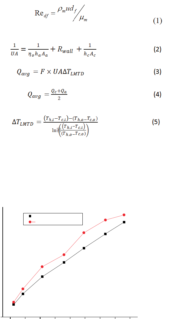
Figure (3) and (4) show the results obtained during the experimentation. The heat
transfer coefficient based on the total surface area of the metal-foam fin and the base
plate is plotted against the Reynold’s number based on the ligament diameter.
Re
df
U
m
ud
f
P
m
(1)
1
=
1
ℎ
+
+
1
ℎ
(2)
= × ∆
(3)
=
+
(4)
2
∆
=
ℎ ,
−
,
−(
ℎ
,
−
,
)
ln
ℎ ,
−
,
(
ℎ
,
−
,
)
(5)
F is the correction factor for a single pass, cross flow heat exchangers[19].Fin
efficiency is calculated based on the adiabatic tip condition.
Fig. 3: Heat transfer coefficient (measured and calculated Calmidi and Mahajan, 2000)
400
350
300
250
200
150
10 20 30 40 50 60 70 80 90
Reynold's No
2502, Page 6

International Refrigeration and Air Conditioning Conference at Purdue, July 12-15, 2010
(measured)
(Calculated)
Pressure drop per unit length(Pa/m)
d
To compare the results, equation (2) provided by Calmidi and Mahajan[7] is used.
The calculation performed using the relationship
h
0.52
Re
0.5
Pr
0.37
k
a
d
f
f
(6)
The experimental data are compared to the model of Calmidi and Mahajan, 2000 [7]
in figure (3). The results show surprisingly good agreement and buttress both the data
and the model. The relationship(6) showed that the values differ less than 5% at low
Reynolds numbers(0.6 m/s) but the difference approaches 10 % at the highest
velocity (4.3 m/s)
Shown in the figure (4) is the pressure drop The pressure drop for metal foam is
assumed to be higher as compared to some other compact heat exchangers and similar
behavior was achieved during the experiments. The fanning friction factor for metal
foam with a face velocity of 3m/s is 0.15 which is 50% more than for multi- louver fin
heat exchanger under the same flow conditions. The results are compared with
equation (3) provided byBhattacharya et al.[5]
dp
Pu
U
a
ff
u
2
(7)
dx K
K
Fig. 4: Pressure drop per unit length (measured and calculated Bhattacharya et al. [5])
7000
6000
5000
4000
3000
2000
1000
0
10 20 30 40 50 60 70 80 90
Reynold's No
The relationship is widely used to estimate the pressure drop through porous media,
but the experimental results show that the difference varies from 76% (213 Pa/m
calculated 49 Pa/m measured) at low face velocity to 17 % (5629 Pa/m calculated
6739 Pa/m measured) at high face velocity. The uncertainty in the measuring device
for pressure difference is
2502, Page 7

International Refrigeration and Air Conditioning Conference at Purdue, July 12-15, 2010
Energy
Balance
Q
Uncertainty Analysis:
The uncertainties in various instruments were reported in Table 1. While conducding
the wind tunnel experiments the first critical step is to achieve the energy balance on
the air side and on the coolant side. Such a balance supports the veracity of the data..
Even with significant care, these problems are unavoidable and resulting a slight heat
transfer mismatch on air and coolant sides. The problems become rather severe at
high face velocities. If the energy balance is defined by the following relationship,
then its variation with Reynolds No based on the ligament diameter is given as
follows (equation (8)).
b a la n ce
Q
Q
Q
Q
a ir co o la n t
Q
t
t
Q
a vg
(8)
Fig 5: Energy balance against Reynold’s no.
14
12
10
8
6
4
2
10 20 30 40 50 60 70 80 90
Reynold
's
No
The trend in the energy balance show that as the air mass flow rate is increased, the
problems like air leakage become more significant as compared to they were at low
air mass flow rates. The uncertainty for the heat transfer coefficient varies from 5.7
% at lowest face velocity (0.6 m/s) to 13.7 % at the highest face velocity (4.3 m/s).
2502, Page 8
International Refrigeration and Air Conditioning Conference at Purdue, July 12-15, 2010
Future work and challenges:
Current results are based on the experiments performed under dry conditions for just
one specimen, which is actually a drop-in-replacement configuration for some current
heat exchangers (louver fins are replaced with metal foam). In order to fully exploit
the performance-enhancing characteristics of metal foams, further experimental work
is required. For that purpose new samples with different configurations and having
different foam properties need to be tested. Bonding the metal-foam fins to the base
surface is perhaps the most challenging task while manufacturing and also the most
costly process if one wants the ideal thermal joint (soldering or brazing). Thermal
epoxies can also work well if they have good thermal conductivity, but the
performance of the brazed metal foam should be tested along with the specimen
employing thermal epoxy as adhesive. Furthermore the performance of the materials
should be tested under wet conditions, where there is condensation on the surface, to
see the water drainage behavior during operational conditions.
Conclusion:
Metal foams are novel materials which can perform well if they are used in compact
heat exchangers. For the two parameters, heat transfer performance and pressure drop,
one has to come up with some ideal conditions in terms of geometry and flow
conditions to get the best performance. There are correlations available to calculate
the heat transfer coefficient and pressure drop. The relationship for the heat transfer
coefficient by Calmidi and Mahajan [2] is accurate enough as the experimental values
are close enough. For the pressure drop performance the relationship by Bhattacharya
[5] work well at high velocities.
Nomenclature:
ff inertial coefficient
fin efficiency
h convective heat transfer coefficient, W/m
2
K
Pr
prendtl No
K permeability, m
2
k thermal conductivity of the fin, W/m.K
u
velocity, m/s
ȣ dynamic viscosity, N/ms
d
f fiber diameter,m
dp pore diameter,m
Ȩ
density, kg/m
3
2502, Page 9
International Refrigeration and Air Conditioning Conference at Purdue, July 12-15, 2010
Subscript:
a air side
c coolant side
m mean value
h,i
hot inlet
h,o
hot outlet
c,i cold inlet
c,o
cold outlet
REFERENCES
[1] Lu, T., Ultralight porous metals: from fundamentals to applications, Acta Mechanica
Sinica, Chinese J. Mech, vol.18, pp.457-479, 2002.
[2] Calmidi, V.V, and Mahajan, R.L., The effective thermal conductivity of high porosity
fibrous metal foams, J. Heat Transfer, vol. 121, pp. 466-471, 1999.
[3] Boomsma, K., and Poulikakos, D., On the effective thermal conductivity of a three-
dimensionally structured fluid-saturated metal foam, Int. J. Heat Mass Transfer, vol.44,
pp.827-836, 2001.
[4] Dai, Z., Nawaz, K., Park, Y., Bock, J., and Jacobi, A.M., Correcting and extending
the Boomsma-Poulikakos effective thermal conductivity model for three-dimensional,
fluid-saturated metal foams, Int. Comm. Heat Mass Trans., in press.
[5] Bhattacharya, A., Calmidi, V.V., and Mahajan, R.L., Thermophysical properties of
high porosity metal foam, Int. J. Heat Mass Transfer, vol. 45, pp.1017-1031,2002.
[6] Tadrist, L., Miscevic, M., Rahli, O., and Topin, F., About the use of fibrous materials
in compact heat exchangers, Experimental Thermal and Fluid Science,vol.28, pp. 193-
199, 2004.
[7] Calmidi, V.V., and Mahajan, R.L., Forced convection in high porosity metal foams, J.
Heat Transfer, vol.122, pp.557–565, 2000.
[8] Zhao, C.Y., Lu, T.J., and Hodson, H.P., Natural convection in metal foams with open
cells, Int. J. Heat Mass Transfer, vol.48, pp.2452-2463, 2005.
[9] Hetsroni, G., Gurevich, M, and Rozenblit, R., Natural convection in metal foam strips
with internal heat generation, Experimental Thermal and Fluid Science, vol. 32, pp.
1740-1747, 2008.
2502, Page 10
International Refrigeration and Air Conditioning Conference at Purdue, July 12-15, 2010
[10] Boomsma, K., Poulikakos, D., and Zwick, F., Metal foams as compact high
performance heat exchangers, Mechanics of Materials, vol.35, pp.1161-1176, 2003.
[11] Zhao, C.Y., Lu, W, and Tassou, S.A., Thermal analysis on metal-foam filled heat
exchangers. Part
ϩ: Tube heat exchangers, Int. J. Heat Mass Transfer, vol.49, pp.2762-
2770, 2006
.
[12] Lu, W., Zhao, C.Y., and Tassou, S.A., Thermal analysis on metal-foam filled heat
exchangers. Part
Ϩ: Metal-foam filled pipes, Int. J. Heat Mass Transfer, vol.49, pp.2751-
2761, 2006.
[13] Mahjoob, S., and Vafai, K., A synthesis of fluid and thermal transport models for
metal foam heat exchangers, Int. J. Heat Mass Transfer, vol.51, pp.3701-3711, 2008.
[14] Ejlali, A., Ejlali, A., Hooman, K., and Gurgenci, H., Application of high porosity
metal foams as air-cooled heat exchangers to high heat load removal systems, Int.
Commun Heat Transf, vol. 36, pp. 674-679, 2009.
[15] Dai, Z., Nawaz, K., Park, Y., Chen, Q.,and Jacobi, A.M., A comparison of metal-
foam heat exchangers to compact multi-louver designs for air-side heat transfer
applications, Proceedings of the Seventh International Conference on Enhanced,
Compact and Ultra-Compact Heat Exchangers: From Microscale Phenomena to
Industrial Applications, San Jose, Costa Rica, 2009, pp. 49–57.
[16] Park, Y., and Jacobi, A. M., The air-side thermal-hydraulic performance of flat-tube
heat exchangers with louvered, wavy, and plain fins under dry and wet conditions, J.
Heat Transfer, vol. 131, 061801, 2009.
[17] Chang, Y.J. and Wang, C.C., A generalized heat transfer correlation for louver fin
geometry, Int. J. Heat and Mass Transfer, vol. 40, pp.533-544, 1997.
[18] Kim, S.Y., Paek, J.W., and Kang, B.H., Flow and heat transfer correlations for
porous fin in a plate-fin heat exchanger, J. Heat Transfer, vol. 122, pp.572-578, 2000.
[19] Incropera, F.P., and DeWitt, D. P., Fundamentals of heat and mass transfer, 4thed.,
John Wiley & Sons, Inc, 1996
[20] Park, Y., Jacobi, A. M., Air-side heat transfer and friction correlations for flat-tube
louver-fin heat exchangers, J. Heat Transfer, vol. 131, 021801, 2009.
2502, Page 11
