
CHEMCAD
User Guide

All material © 2021 Chemstations, Inc.

CHEMCAD User Guide i
CHEMCAD User Guide
Table of Contents
Chapter 1 – Introduction to CHEMCAD
Overview of CHEMCAD and Its Uses .................................................................................................... 1
CHEMCAD Products and Features ..................................................................................................... 3
CHEMCAD Features by Module ......................................................................................................... 4
UnitOps by Module ............................................................................................................................... 5
Chapter 2 – Getting Started with CHEMCAD
Creating a User Support Center Account ............................................................................................... 8
Downloading the Software ....................................................................................................................... 9
Installing the software ............................................................................................................................... 9
Licensing CHEMCAD ............................................................................................................................. 12
Types of CHEMCAD Licenses ........................................................................................................... 12
License Settings ..................................................................................................................................... 12
Updating a License ............................................................................................................................... 14
Getting Help with CHEMCAD .............................................................................................................. 17
Online Help ........................................................................................................................................... 17
The Chemstations Website .................................................................................................................. 17
Contacting Chemstations Technical Support ................................................................................... 17
Chapter 3 – The CHEMCAD Interface
The CHEMCAD Window ....................................................................................................................... 19
The Command Ribbon ......................................................................................................................... 20
The Quick Access Toolbar ................................................................................................................... 20
The Workspace ..................................................................................................................................... 21
The Explorer Pane ................................................................................................................................ 21
The Palette Pane .................................................................................................................................... 23

Table of Contents
ii CHEMCAD User Guide
The Messages Pane ............................................................................................................................... 25
Other CHEMCAD Window Commands .......................................................................................... 26
Customizing the CHEMCAD Screen .................................................................................................... 26
Viewing and Hiding Screen Elements ............................................................................................... 27
Resizing and Moving Items ................................................................................................................ 27
Pinning and Unpinning Panes............................................................................................................ 28
Flowsheet Drawing Tools ....................................................................................................................... 29
The Workspace Group ......................................................................................................................... 30
The Insert Group .................................................................................................................................. 31
The Objects Group ................................................................................................................................ 32
Other Useful Interface Hints .................................................................................................................. 34
Undo and Redo ..................................................................................................................................... 34
Flowsheet Quickview .......................................................................................................................... 34
Adjusting Your View of the Workspace ........................................................................................... 35
Locking Flowsheet Elements .............................................................................................................. 36
Chapter 4 – Working with Simulation Files
About CHEMCAD Simulation Files ..................................................................................................... 39
User Components in CHEMCAD ...................................................................................................... 40
Example Files ........................................................................................................................................ 40
Opening an Existing Simulation ............................................................................................................ 40
Creating a New Simulation .................................................................................................................... 41
Saving a Simulation ................................................................................................................................. 41
Saving Different Cases for the Same Simulation ............................................................................. 42
E-mailing a Simulation ............................................................................................................................ 43
Sending from Within CHEMCAD ..................................................................................................... 43
Attaching to an E-mail ......................................................................................................................... 43
Working with CHEMCAD Files from Previous Versions .................................................................. 44
Chapter 5 – Building and Using a Basic Simulation
Starting a New Simulation ...................................................................................................................... 45
Specifying Engineering Units ................................................................................................................. 46
Selecting Chemical Components ........................................................................................................... 46
Finding a Component .......................................................................................................................... 47
Adding a Component .......................................................................................................................... 49
Changing the Order of Selected Components .................................................................................. 49
Removing Items from the Selected Components List ..................................................................... 50

Table of Contents
CHEMCAD User Guide iii
Selecting K-value and Enthalpy Options .............................................................................................. 50
Using the Thermodynamic Suggestions Dialog .............................................................................. 50
Manually Selecting Thermodynamics Settings ................................................................................ 51
Drawing the Flowsheet ........................................................................................................................... 52
Adding UnitOps ................................................................................................................................... 52
Feed and Product Arrows ................................................................................................................... 56
Drawing and Connecting Streams ..................................................................................................... 56
Defining Streams ...................................................................................................................................... 60
Thermodynamic Properties ................................................................................................................ 61
Stream Composition ............................................................................................................................. 61
Total Flow Properties ........................................................................................................................... 61
Specifying Equipment Parameters ........................................................................................................ 62
Running the Simulation .......................................................................................................................... 63
Reviewing the Results ............................................................................................................................. 63
Chapter 6 – Using CHEMCAD for High-Fidelity Modeling
What is high-fidelity modeling? ............................................................................................................ 65
Criteria for High-fidelity Modeling ....................................................................................................... 66
Introduction to Equipment Sizing ......................................................................................................... 66
High-fidelity Modeling and Sizing for Common UnitOps ................................................................ 67
Piping ..................................................................................................................................................... 67
Pumps, Compressors, and Expanders ............................................................................................... 68
Vessels and Tanks ................................................................................................................................ 68
Valves ..................................................................................................................................................... 70
Columns ................................................................................................................................................. 70
Heat Exchangers ................................................................................................................................... 73
Relief Devices ........................................................................................................................................ 74
Licensing Considerations for High-fidelity Modeling........................................................................ 75
Chapter 7 – Building and Using a Dynamic Simulation
What do we mean by dynamics? ........................................................................................................... 77
Licensing Considerations ........................................................................................................................ 77
Additional Input for Dynamic Operation ............................................................................................ 78
Strategies for Dynamic Simulations ................................................................................................... 79
Setting up Dynamic Operation .............................................................................................................. 79
Switching to Dynamics ........................................................................................................................ 79
Setting the Run Time ............................................................................................................................ 80

Table of Contents
iv CHEMCAD User Guide
Selecting Streams and UnitOps .......................................................................................................... 81
Initial State Settings ................................................................................................................................. 82
Save As Initial State .............................................................................................................................. 82
Reset to Initial State .............................................................................................................................. 83
Running a Dynamic Simulation ............................................................................................................. 83
Run from Initial State ........................................................................................................................... 84
Run from Current State ....................................................................................................................... 84
Run One Step at a Time ....................................................................................................................... 84
Output from Dynamic Simulations ....................................................................................................... 85
Reviewing the Flowsheet Specifications ........................................................................................... 85
Plotting Dynamic Results .................................................................................................................... 85
Text-based Dynamic Reports .............................................................................................................. 86
Chapter 8 – Output and Reports
The Basics: Generating Individual Charts and Reports ..................................................................... 87
The Charts Gallery ................................................................................................................................... 88
Thermodynamic ................................................................................................................................... 88
Stream .................................................................................................................................................... 89
UnitOp ................................................................................................................................................... 90
Dynamic ................................................................................................................................................. 90
User......................................................................................................................................................... 91
Chart Tab Commands ............................................................................................................................. 91
Edit Group ............................................................................................................................................. 92
Chart Settings Group ........................................................................................................................... 92
X Axis, Y Axis, Secondary Y Axis, and Tertiary Y Axis Groups.................................................... 93
A Axis, B Axis, and C Axis Groups ................................................................................................... 94
Window Group ..................................................................................................................................... 94
Adding Chart Data Manually with the User Series Feature .............................................................. 94
Adding a New User Series .................................................................................................................. 94
Displaying a User Series on a Chart .................................................................................................. 95
Editing User Series Values .................................................................................................................. 95
Importing Values for a User Series .................................................................................................... 95
Adding Data Points to a Ternary Chart ............................................................................................ 96
Deleting a User Series .......................................................................................................................... 96
The Reports Gallery ................................................................................................................................. 96
Stream .................................................................................................................................................... 97
UnitOp ................................................................................................................................................... 98

Table of Contents
CHEMCAD User Guide v
Distillation ............................................................................................................................................. 98
Flowsheet ............................................................................................................................................... 99
Dynamic ............................................................................................................................................... 100
UnitOp and Stream Groups .................................................................................................................. 100
Creating a Group ................................................................................................................................ 100
UnitOp and Stream Group Commands .......................................................................................... 101
Choosing Groups in the Select Streams and Select UnitOp Dialogs ........................................... 102
Report Viewer Setup .............................................................................................................................. 102
Printing CHEMCAD Reports and Charts .......................................................................................... 103
Consolidated Reports and the CHEMCAD Report Writer .............................................................. 103
Choosing and Ordering Report Sections ........................................................................................ 104
Selecting Flowsheet Elements ........................................................................................................... 105
Formatting Report Sections ............................................................................................................... 105
Naming the Report and Choosing a Destination ........................................................................... 106
Selecting a Report Viewer for Consolidated Reports .................................................................... 107
Property Sets ........................................................................................................................................... 107
Built-in Property Sets ......................................................................................................................... 107
User-created Property Sets ................................................................................................................ 107
Different Sets for Different Purposes ............................................................................................... 107
The Property Set Preferences Dialog ............................................................................................... 108
Active Set Designations ..................................................................................................................... 109
Editing a Property Set ........................................................................................................................ 109
Creating a New Property Set ............................................................................................................ 109
Copying an Existing Property Set .................................................................................................... 110
Format Tab Options ........................................................................................................................... 111
Resetting Built-in Property Sets ........................................................................................................ 111
Deleting a User-added Property Set ................................................................................................ 111
Using the Property Set Library ......................................................................................................... 111
Sharing Property Sets with Other CHEMCAD Users ................................................................... 113
Creating Process Flow Diagrams ......................................................................................................... 113
Adding Flowsheet Databoxes ........................................................................................................... 113
Using Title Blocks ............................................................................................................................... 117
Using the Layers Feature for Selective Viewing and Printing ..................................................... 119
Printing a Process Flow Diagram ..................................................................................................... 122

Table of Contents
vi CHEMCAD User Guide
Chapter 9 – Customizing CHEMCAD
Flowsheet Templates ............................................................................................................................. 123
Creating a Template ........................................................................................................................... 124
Viewing a Template’s Properties ..................................................................................................... 124
Applying a Template ......................................................................................................................... 124
Renaming or Deleting a Template ................................................................................................... 125
Creating Custom Components ............................................................................................................. 125
Adding a Single Component ............................................................................................................ 125
Defining a Petroleum Assay Range ................................................................................................. 129
Importing a Neutral File .................................................................................................................... 130
Customizing Thermodynamics ............................................................................................................ 130
Creating a Custom K-value or Enthalpy Model ............................................................................ 131
Creating a Custom Mixing Rule ....................................................................................................... 132
Visual Basic Applications (VBA) ......................................................................................................... 132
Defining a Reaction, Mixing Rule, or UnitOp ................................................................................ 132
Using a VBA-defined Reaction ......................................................................................................... 133
Using a VBA-defined Mixing Rule .................................................................................................. 134
Using a VBA-defined UnitOp ........................................................................................................... 134
Customizing UnitOp Palettes ............................................................................................................... 135
Creating a Custom Palette ................................................................................................................. 135
Copying an Existing Palette .............................................................................................................. 135
Renaming a Palette ............................................................................................................................. 136
Using a Custom Color Scheme to Change UnitOp Symbol Colors ............................................. 136
Resetting Palettes to Default Configuration ................................................................................... 137
Creating Custom UnitOp Symbols ...................................................................................................... 137
Starting the UnitOp Designer ........................................................................................................... 138
Drawing and Sizing the Symbol ....................................................................................................... 138
Saving the Symbol Drawing ............................................................................................................. 139
Adding and Locating Ports ............................................................................................................... 139
Specifying Ports .................................................................................................................................. 139
Publishing the UnitOp Symbol ........................................................................................................ 140
Time-saving Strategies for Creating Multiple Custom Symbols ................................................. 141
Creating Custom UnitOps .................................................................................................................... 143
Creating a Custom UnitOp Dialog Box ........................................................................................... 144
Customized Costing Calculations ....................................................................................................... 145

Table of Contents
CHEMCAD User Guide vii
Chapter 10 – Data Interfaces
Excel Data Mapping .............................................................................................................................. 151
Creating an Excel Data Map ............................................................................................................. 152
Data Map Execution Rules ................................................................................................................ 155
Creating Excel UnitOps ......................................................................................................................... 157
Specification Sheets ................................................................................................................................ 157
Using CHEMCAD as an OPC Server .................................................................................................. 158
OPC Applications ............................................................................................................................... 158
OPC Compliance ................................................................................................................................ 159
Enabling CHEMCAD as an OPC Server ......................................................................................... 159
Reading and Writing Values to CHEMCAD Using OPC ............................................................. 159
OPC Server Operations ..................................................................................................................... 160
CHEMCAD OPC Namespace ........................................................................................................... 160
COM Interfaces ....................................................................................................................................... 161
Connecting Excel and CHEMCAD: A Simple COM Interface ..................................................... 161

Table of Contents
viii CHEMCAD User Guide

CHEMCAD User Guide 1
Chapter 1
Introduction to CHEMCAD
Welcome to CHEMCAD, a powerful and effective software tool for chemical process
simulation. Whether you’re a new or experienced CHEMCAD user, you’ll appreciate
the program’s user-friendly, feature-rich interface. Creating flowsheets and running
simulations is fast and easy with CHEMCAD, and the program is highly
customizable to fit your needs and the way you work.
This User Guide will help you get up and running with CHEMCAD, from
installation and licensing to details on using dynamics and data interfaces.
Overview of CHEMCAD and Its Uses
Today’s chemical processing industry (CPI) faces numerous challenges:
unpredictable fuel and feedstock costs, reduced engineering staff, shorter product
life cycles, increased global competition, and increased regulation. These challenges
require that CPI companies seek out and use the best tools to increase productivity
and improve engineering decisions.
CHEMCAD is a powerful and flexible chemical process simulation environment,
built around three key values of innovation, integration, and open architecture.
These values create important advantages for CHEMCAD users:
• The latest chemical engineering techniques at your fingertips
• All functionality united in a single software environment
• Seamless connection to the chemical engineering computing environment, with
links to tools such as MS Excel and Word and interfaces such as COM, DCOM,
OPC, CAPE-OPEN, and XML

Introduction to CHEMCAD
2 CHEMCAD User Guide
CHEMCAD combines a state-of-the-art graphical user interface (GUI), an
extensive chemical component database, a large library of thermodynamic data, and
a library of the most common unit operations to give users the ability to provide
significant and measurable returns on their investment. In addition, the program is
customizable to allow custom chemicals, thermodynamics, unit operations,
calculations, and reporting—all ingredients for a powerful user experience.
CHEMCAD is capable of modeling continuous, batch, and semi-batch processes,
and it can simulate both steady-state and dynamic systems. This program is used
extensively around the world for the design, operation, and maintenance of chemical
processes in a wide variety of industries, including oil and gas exploration,
production, and refining; gas processing; commodity and specialty chemicals;
pharmaceuticals; biofuels; and process equipment manufacturing.
Within all these industries, chemical engineers work every day with CHEMCAD
to address a variety of challenges:
• Initial design of new processes
• Optimization or de-bottlenecking of existing processes
• Performance monitoring of processes
• Design and rating of process equipment such as vessels, columns, heat
exchangers, piping, valves, and instrumentation
• Evaluation of safety relief devices
• Heat exchanger sizing
• Pressure and flow balancing of complex piping networks
• Reconciliation of plant data
• Economic comparisons of process alternatives
• Advanced process control (APC), including model predictive control (MPC),
real-time optimization (RTO), and operator training systems (OTS)
• Scale-up of processes from lab-scale to pilot-scale, and from pilot-scale to full-
scale
• Binary interaction parameter (BIP) regression from process or lab data
• Batch reaction rate regression from process or lab data
No matter how complex your process, CHEMCAD is capable of delivering the
results you need to stay competitive in an increasingly fast and fluid global market.
Easy to learn and highly customizable, CHEMCAD can put future-proof solutions
within easy reach of your engineering staff.

Getting Started with CHEMCAD
CHEMCAD User Guide 3
CHEMCAD Products and Features
The CHEMCAD suite consists of several modules that serve specific purposes.
Depending on your particular needs, you may have purchased some or all of these
modules. The following are brief descriptions of the various CHEMCAD modules
and their most common uses.
CC-STEADY STATE
The main CHEMCAD product, known as CC-STEADY STATE, enables you to
design new processes, rate existing processes, and optimize processes in steady state.
CC-DYNAMICS
The module known as CC-DYNAMICS makes it possible to design new and rate
existing processes using a dynamic simulation. This module is fully integrated with
CHEMCAD to make switching between steady state and dynamics easy and
intuitive. Using CC-DYNAMICS, you can easily simulate everything from simple
vessel accumulation to complex control systems on columns. This module also
provides tools for simulation of continuous stirred-tank reactors (CSTRs), including
complex reaction rate and pressure calculation.
CC-BATCH
The CC-BATCH product enables you to design, rate, or optimize a batch distillation
column. CC-BATCH includes a scheduling interface to allow an “operation step”
approach to simulation of batch columns.
CC-THERM
The CC-THERM product lets you design a single heat exchanger, or vet a vendor’s
heat exchanger design. It is also ideal for customers who want to rate existing
exchangers in new service, or to perform calculations on hypothetical situations. CC-
THERM can simulate shell-and-tube, air-cooled, plate-and-frame, and double-pipe
exchangers. Full integration with CHEMCAD makes it possible to calculate exit
conditions from exchanger geometry for high-fidelity simulations.
CC-SAFETY NET
The CC-SAFETY NET product provides the capability to design or rate piping
networks and safety relief devices and systems, in both steady-state and dynamic
systems. The steady-state features of CC-SAFETY NET are included with CC-
STEADY STATE. This product enables users to make simultaneous flow- and
pressure-balanced simulations—even in reverse-flow situations—for single- or
multi-phase flow.
CC-FLASH
The CC-FLASH module provides physical property and phase equilibrium data, as
well as property prediction and regression. CC-FLASH is a subset of CC-STEADY
STATE, and is meant for customers who do not need full flowsheet simulation tools.

Introduction to CHEMCAD
4 CHEMCAD User Guide
CHEMCAD Features by Module
The following matrix lists the features associated with each component of the
CHEMCAD suite. For a more detailed explanation, or to inquire about a particular
component or feature, please contact Chemstations or your CHEMCAD distributor
(see complete contact information at www.chemstations.com).
CC-
STEADY STATE
CC-
DYNAMICS
CC-BATCH
CC-THERM
CC-
SAFETY NET
CC-FLASH
VB/COM/OPC/Data Map
Sensitivity/optimization
Sizing (line/valve/orifice/vessel)
Run steady state
Run dynamics
Run recycles
Costing
Reconciliation
Sizing columns
Sizing heat exchangers
Economics
Reports (incl. Excel)
DIERS
CO
2
solid
Hydrates
Depress
TOC/COD
Pure regression
BIP regression
Electrolyte regression
Rate regression
Units calculator
Execute parser
Environmental report
Simple calculator
Spec sheet

Getting Started with CHEMCAD
CHEMCAD User Guide 5
UnitOps by Module
The availability of certain unit operations, or UnitOps, in CHEMCAD simulations is
a function of which modules you have licensed. The following matrix lists all
available UnitOps and the CHEMCAD modules associated with them.
CC-
STEADY STATE
CC-
DYNAMICS
CC-BATCH
CC-THERM
CC-
SAFETY NET
CC-FLASH
Baghouse filter
Batch column
Calculator
Centrifuge
Component separator
Compressor
Control valve
Controller
Crusher/grinder
Crystallizer
Cyclone
Divider
Electrostatic precipitator
Equilibrium reactor
Excel unit
Expander
Fired heater
Flash
Gibbs reactor
Heat exchanger
Hydrocyclone
Kinetic reactor
Liquid/liquid extractor
LNGH exchanger
Loop
Membrane
Mixer

Introduction to CHEMCAD
6 CHEMCAD User Guide
CC-
STEADY STATE
CC-
DYNAMICS
CC-BATCH
CC-THERM
CC-
SAFETY NET
CC-FLASH
Node
PID controller
Pipe simulator
Polymer reactor
Pump
Ramp controller
Relief device
Run subflowsheet META unit
SCDS distillation column
Screen
Sedimentator
Shortcut column
Solids dryer
Solids washer
Stoichiometric reactor
Stream reference
Tank
Time delay
Time switch
Tower distillation column
Tower plus distillation column
User-added module
Vacuum filter
Valve
Venturi scrubber
Vessel
Vessel reactor

CHEMCAD User Guide 7
Chapter 2
Getting Started with CHEMCAD
To start using CHEMCAD, you’ll need to obtain the software, install it on your
computer, and set up a valid software license. This chapter provides step-by-step
instructions for these tasks.
Before you begin, please ensure that your PC meets the recommended system
requirements, as listed below. It’s also a good idea to find out whether your copy of
CHEMCAD will rely on a
network license; if it will, make
sure to ask your network
administrator for all the
information that you’ll need
when installation is complete
and it’s time to set up
licensing.
If you’ll be using a
hardware dongle to license
CHEMCAD, make sure the
dongle is inserted into a USB
port before you attempt to run
the program.
To obtain the CHEMCAD
installation file, you’ll need a live Internet connection and a web browser. You can
either download the file directly onto the system where you plan to install
CHEMCAD, or download the file and place it onto a portable drive for installation
CHEMCAD System Requirements
Processor: 1 GHz or faster, 32- or 64-bit
Operating system: Windows 7 or later
(all 32- and 64-bit versions)
RAM: 1 GB for 32-bit, or 2 GB for 64-bit
Video card: DirectX 9 graphics device with
WDDM 1.0 or higher driver
Display resolution: 1920 x 1080 or higher
Hard disk space: 16 GB (32-bit) or 20 GB (64-
bit) for installation, 1 GB free space
recommended
Productivity software: Some features require
Mi ft Offi ®

Getting Started with CHEMCAD
8 CHEMCAD User Guide
on a different computer. In either case, the download process requires that you log
into Chemstations’ User Support Center.
Creating a User Support Center Account
The first time you visit Chemstations’ User Support Center, you’ll need to set up a
user account. Follow the steps below to do this.
1. On the Chemstations website home page (www.chemstations.com), click the
User Login button in the upper right area of the screen.
2. On the login screen, click the Forgot your password? button.
Figure 2-01: Clicking the Forgot your password? button on the login screen
3. On the next screen, enter a valid e-mail address, and click the Send button. Be
sure to use your company address, as the login system will match your address
against our customer database.
4. If your address is found, you will receive an e-mail from CHEMCAD Technical
Support, offering a link to reset your password. Follow the instructions in the e-
mail and at the password reset screen to complete your registration.
Note: In the event you do not receive a password reset e-mail within 24 hours, your
address may not have been found in our database. Please contact Chemstations
Technical Support ([email protected]) for assistance.

Getting Started with CHEMCAD
CHEMCAD User Guide 9
Downloading the Software
Once your user login is established, you can download the latest version of
CHEMCAD from the Chemstations website (www.chemstations.com).
On the home page, click the User Login button. The next screen will invite you to
sign in. When you have done this, click the Downloads link at the top of the screen.
The resulting Downloads list will include the .exe version of the latest
CHEMCAD installation file. When you have downloaded this file to your local
system, you can begin installation.
Installing the software
Locate the installation file, called CHEMCAD_version number_Setup.exe, and
double-click it to start the installation. The first InstallShield Wizard screen appears.
Figure 2-02: The CHEMCAD NXT - InstallShield Wizard screen
Click Next to begin the installation process. The License Agreement screen
appears, listing the terms of the CHEMCAD standard license. Once you’ve read and
understood the license terms, you’ll need to click the I accept the terms in the license
agreement button before you can click Next to proceed. Note that you have the option
to print a copy of the license agreement from this screen.
Figure 2-03: The License Agreement screen

Getting Started with CHEMCAD
10 CHEMCAD User Guide
The Destination Folder screen appears next, displaying the name of the folder
into which the CHEMCAD files will be installed by default. Normally, this
destination is C:\Program Files\Chemstations\CHEMCAD (or some variation, based
on your version of Windows), and it is recommended that you use this location
unless you have a specific need to install the program elsewhere. Click the Change
button if you want to change the file destination, or click Next to accept the
suggested destination and proceed.
Figure 2-04: The Destination Folder screen
The Setup Type screen now appears, offering a choice between complete and
custom installation. Each type of installation is described on the screen. Either accept
the default setting of Complete or click Custom to select specific components to
install, then click Next to proceed.
Figure 2-05: The Setup Type screen
This brings you to the Ready to Install the Program screen. Note that on this
screen, and in fact on any screen in the installation process, you can click Back to
return to a previous screen and verify or change your installation options. If you are
satisfied with your settings as they are, click Install to start the installation.

Getting Started with CHEMCAD
CHEMCAD User Guide 11
Figure 2-06: The Ready to Install the Program screen
The Installing CHEMCAD Suite screen appears, showing the progress of your
installation with a green status bar.
Figure 2-07: Status bar showing the progress of CHEMCAD installation
During installation, you may notice a second, smaller installation window that
pops up. This shows the progress of various software components that are being
found and installed so that CHEMCAD installation may proceed. To ensure
successful completion of the install procedure, be sure to leave this window open; it
will close automatically when all components are in place.
Figure 2-08: Software component installation message
When installation is complete, you’ll see one final screen, which states that the
InstallShield Wizard has completed installation of the CHEMCAD Suite. Click
Finish to close the installer window.

Getting Started with CHEMCAD
12 CHEMCAD User Guide
Figure 2-09: The InstallShield Wizard Completed screen
Licensing CHEMCAD
Before you can use CHEMCAD, you’ll need to set up a licensing scheme of some
type. Depending on your particular licensing agreement, you will use one of several
types of licenses to run CHEMCAD.
Types of CHEMCAD Licenses
The various types of CHEMCAD licenses are designed to fit different users’
software, hardware, and networking needs. Most licenses require the use of a
hardware device, commonly known as a dongle, to run the program.
The dongle simply plugs into a USB port on the computer, and must be plugged
in any time the program runs. If you work on a network with other CHEMCAD
users, your license may rely on a dongle plugged into a network server elsewhere in
your organization, rather than one plugged directly into your computer.
You or your organization may use one of the following types of dongles:
• SuperPro single-user dongle
• SuperProNet dongle for network use
In some instances, software licensing is provided without the use of a hardware
device:
• RMS License Manager software, which runs over a local- or wide-access
network
• System Authorization, a method that authorizes a single-user machine for
a limited time (used for software evaluation)
License Settings
To run CHEMCAD for the first time, make sure that your dongle (if applicable) is
plugged in properly, and then start the program. From the Windows Start menu,
select All Programs > Chemstations > CHEMCAD NXT.

Getting Started with CHEMCAD
CHEMCAD User Guide 13
Note: A Standard License screen appears only the first time that you run
CHEMCAD after installation. After you have reviewed the license agreement, click
Yes to continue.
The program opens, displaying a CHEMCAD splash screen. After a short time,
this screen is replaced by the CHEMCAD License Monitor dialog box, which
displays information about the license(s) that your computer is using to run
CHEMCAD.
Figure 2-10: The CHEMCAD License Monitor, displaying licenses from a local hardware dongle
Note: In some cases, this dialog may initially display with the title Searching for
Licenses, indicating that CHEMCAD has not yet detected a valid license. If your
computer is experiencing slow communication with the license server system,
CHEMCAD may simply need more time to detect the license(s). As soon as any
valid license is found, the CHEMCAD License Monitor title will appear and licensing
will proceed.
Normally, this dialog box remains in view for only a few seconds, listing all
product licenses that CHEMCAD has obtained. During that time, you can click
anywhere in the dialog box to keep it open. If you do not click in the dialog box, it
disappears from view, but you can bring it back up at any time by clicking the File
tab and then selecting Licensing.
While the CHEMCAD License Monitor dialog box is open, you can view the
various CHEMCAD licenses detected for your system and see what method (and
where applicable, which server) is being used to obtain those licenses. If your
organization uses RMS License Manager or a SuperProNet hardware key, you can
also see which other users currently hold various product licenses.
For network licenses, you can right-click a server name under a particular
product and select a licensing preference (on demand, always, or never) as shown
below.

Getting Started with CHEMCAD
14 CHEMCAD User Guide
Figure 2-11: Selecting a network licensing preference
You can use the always or never setting to turn licensing for a product absolutely
on or off, respectively. The on demand setting secures a license only when you begin
to use a specific CHEMCAD feature controlled by a certain product. This setting is
ideal in most situations, as it leaves unused licenses available for other users.
To close the CHEMCAD License Monitor screen, click the Continue button, or
click the
X in the top right corner of the screen.
Updating a License
CHEMCAD dongles require re-programming on a regular basis—either once a year
or more often, depending on your licensing agreement. This is a security measure to
reduce the likelihood that your dongle will be stolen and misused.
The dongle that you use is programmed to work only through the licensed time
period, and when that time has elapsed, the dongle must be updated before you can
continue using CHEMCAD.
Updating a dongle is a relatively simple procedure. Before your license
expiration, you or your software administrator should receive an e-mail from
Chemstations, with what’s known as a configuration file included as an attachment.
You should save this file to your Windows desktop as soon as you receive it.
Note: If you’ve updated the same dongle in the past, the new configuration file
should have the exact same file name as the previous one. If, while saving the file to
your desktop, you see a Windows message about an existing file with the same
name, you should overwrite the old file (which in any case cannot be used again),
replacing it with the new one.
It’s important to ensure that your configuration file matches your dongle. The
configuration file should be a .DNG file whose name includes a four- or five-digit
code; this code must match the number stamped onto your dongle. If the numbers

Getting Started with CHEMCAD
CHEMCAD User Guide 15
don’t match, contact your software administrator or Chemstations support to resolve
the issue.
The update e-mail also specifies the date on which you’ll need to update your
dongle. Before that date arrives, follow this procedure to perform the update:
1. Start the CHEMCAD program and click the File tab. On the command list at
left, click Licensing. This brings up the CHEMCAD License Monitor dialog
box, which displays the status of all applicable CHEMCAD product licenses,
along with your dongle type and number.
Figure 2-12: The CHEMCAD License Monitor dialog box
2. Click Setup to bring up the License Setup dialog box, then click Update
dongle as shown below.
Figure 2-13: Clicking Update dongle within the License Setup dialog box
3. The dialog box now lists all licensing dongles and displays a field for
entering the full path and file name for the dongle update file. Click Browse
to navigate to the update file.

Getting Started with CHEMCAD
16 CHEMCAD User Guide
Figure 2-14: Browsing for the dongle update file
4. In the Open dialog box, navigate to the location where you saved the .DNG
configuration file. Normally, this is the Windows desktop; if you saved your
configuration file there, click Desktop to tell CHEMCAD where to look for
the file, then select the .DNG file and click Open.
5. The License Setup dialog box now displays the directory path and file name
for the selected .DNG file. Click OK to update the dongle.
Figure 2-15: Updating the dongle with the selected update file
6. CHEMCAD re-programs the dongle, and then displays a pop-up window
stating that the update is complete.
Figure 2-16: Successful re-programming of a CHEMCAD dongle
7. Click OK to close the pop-up window. If the CHEMCAD License Monitor
screen appears, click Continue to close it.
You should now be able to proceed normally in CHEMCAD.

Getting Started with CHEMCAD
CHEMCAD User Guide 17
Getting Help with CHEMCAD
If you find that you have questions that are not addressed in this User Guide, you
can turn to several resources for CHEMCAD help.
Online Help
At any time while running CHEMCAD in an active window, you can press the [F1]
key to bring up the CHEMCAD Help screen that’s most appropriate to the task you
are currently performing or the dialog box currently displayed.
In some situations, pressing [
F1] will bring up the main CHEMCAD Help
window instead of a particular help screen. From there, you can click the Contents,
Index, or Search tab in the upper left corner of the CHEMCAD Help window, and
use these tools to find the information you need.
You can also go directly to the main CHEMCAD Help window by clicking Help
in the top right corner of the program screen. Regardless of how you open
CHEMCAD Help, it always opens in a separate window that does not interfere with
the operation of the CHEMCAD program.
The Chemstations Website
To find the most recent updates of the CHEMCAD software, manuals, and various
training tools, go to www.chemstations.com. There you’ll find the following items
available for download:
• The latest release of CHEMCAD
• A list of updates implemented in the most recent release
• CHEMCAD documentation and demos
Contacting Chemstations Technical Support
If you are unable to solve a problem or find the answer to a question using this User
Guide or the other tools listed here, you can contact Chemstations’ technical support
staff for assistance.
Our technical support engineers
are available via e-mail, or by phone
Monday through Friday, 7:00 AM
through 6:00 PM Central Standard
Time.
Outside of the United States, please see www.chemstations.com for regional
contact information.
Phone: 713.978.7700
Toll-free (U.S. and Canada): 800.243.6223
FAX: 713.978.7727
E-mail: support@chemstations.com

Getting Started with CHEMCAD
18 CHEMCAD User Guide

CHEMCAD User Guide 19
Chapter 3
The CHEMCAD Interface
This chapter takes you on a tour of the CHEMCAD screen, including the tabbed
command ribbon, the main areas of the screen, and the flowsheet drawing tools. It
also shows you some ways that you can customize the screen and various features so
that they best suit your own way of working.
The CHEMCAD Window
When you launch the CHEMCAD program for the first time, you’ll see a screen with
a tabbed ribbon at the top, a large open area in the middle, and various panes, or
specialized areas, at the edges of the screen.
Figure 3-01: The full CHEMCAD program window
Window controls
Command ribbon
Explorer pane
Workspace
Palette pane
Messages pane
Status bar
Quick Access Toolbar
Ribbon tabs

The CHEMCAD Interface
20 CHEMCAD User Guide
The Command Ribbon
The commands for using CHEMCAD are arranged into a tabbed ribbon, which is
located at the top of the program window. Each tab brings up a different set of
commands, with items grouped according to topic.
When you launch the program, the Home tab is selected, showing the most
commonly used CHEMCAD commands. To access any other groups of commands
(known as command categories), simply click the corresponding tab.
Some of the tab names are commonly found in Windows programs—namely
File, Home, View, Tools—while other tabs items such as Thermophysical,
Component Database, and Sizing are more specific to chemical process simulation.
Once you click any tab, the ribbon will display a series of related commands.
To discover the use of any item on the command ribbon, simply point your
mouse cursor at the button and watch for the tooltip to appear, as shown below.
Figure 3-02: Viewing a button’s tooltip
Note that the File tab behaves differently than the other tabs. Clicking this tab
brings up a list of commands that are applied at the file or program level, including
opening, closing, or saving a simulation; printing a flowsheet or simulation notes;
and setting up licensing and various program preferences. It’s a good idea to take a
few minutes to familiarize yourself with these commands as you begin to work with
the program.
The Quick Access Toolbar
Above the command ribbon, in the top left corner of the CHEMCAD screen, you’ll
find the Quick Access Toolbar. This toolbar provides one-click access to important
and commonly used commands—New, Open, Save, Undo, Redo, and Run All—
regardless of which command ribbon is currently selected.
Like most other areas of the CHEMCAD interface, the Quick Access Toolbar can
be customized to fit your needs. Click the down arrow at the right end of the toolbar
to access the customization options, which include turning off any of the default
commands or displaying the Quick Access Toolbar below the command ribbon.
Figure 3-03: The default commands on the Quick Access Toolbar

The CHEMCAD Interface
CHEMCAD User Guide 21
The Workspace
The area in the middle of the screen is known as the workspace. This is the main focus
of the CHEMCAD window, the place where you’ll build and edit flowsheets, view
charts and reports, and run and tweak process simulations.
When you first launch CHEMCAD, the workspace is empty. When you start to
build a flowsheet or open an existing simulation, the flowsheet displays in the
workspace.
The workspace uses tabs to enable you to switch between an open simulation and
any related features, such as Excel Data Maps, reports, and charts. At the bottom of
the workspace area, you’ll see one or more tabs whenever a simulation is open.
Each workspace tab includes a button marked with an
X; to close any tab, simply
click that tab’s
X button.
Figure 3-04: The bottom of the workspace area, showing several tabs and their X buttons
Note that any time you’ve closed a simulation and haven’t yet opened another
file, the workspace displays as an empty space.
The Explorer Pane
Along the left edge of the CHEMCAD window, you’ll see an area with a title bar at
the top that reads Explorer. At the bottom of the Explorer pane are three tabs called
Recent Files, Simulation, and Visual Basic. To view the contents of a tab, simply
click the tab name.
Figure 3-05: Explorer pane tabs
The Explorer pane tabs are presented in a tree format, with items organized into a
multi-level hierarchy. The default view shows only top-level items, but you can
expand each item to view second-level items, third-level items, and so forth.
At the left of each top-level item is a small triangle that points to the right. To
expand an item, click the triangle. Two things happen simultaneously when you
click: the tree expands to show that item’s contents, and the triangle shifts to point
downward. You can hide (or collapse) the lower-level items again by clicking the
triangle again. Figure 3-06 shows an example of an Explorer item in collapsed and
expanded view.

The CHEMCAD Interface
22 CHEMCAD User Guide
Figure 3-06: Clicking to expand an item (left); the resulting view (right)
Expanding and collapsing items in the Explorer tabs is one way that you can
make the best use of your screen space when working in CHEMCAD.
The Recent Files Tab
The Recent Files tab is selected by default when you first launch CHEMCAD. This
tab lists all the simulation files that you have opened lately, starting with the most
recent. When you first install CHEMCAD, the list is empty, but with every
simulation that you open—new files or existing ones such as built-in examples—the
list will grow, providing convenient access to files that you use frequently.
To open a simulation from the Recent Files list, simply double-click the file name
in the list.
The Simulation Tab
The Simulation tab displays by default any time a simulation is open. It provides a
series of shortcuts to common commands and settings, including:
• Components: Includes one-click access to component, electrolyte, and solids
selection
• Thermodynamics: Provides quick access to thermodynamic settings and
transport properties
• Flowsheet: Allows quick editing of UnitOp and stream data
• Sensitivity Analyses: Provides a convenient way to create, edit, and run
sensitivity analyses
• Data Maps: Enables you to create or set execution rules for a Data Map
without using the menu
• Saved Charts: Provides quick access to previously saved charts for this
simulation

The CHEMCAD Interface
CHEMCAD User Guide 23
• Groups: Provides an easy way to categorize UnitOps, streams, and
components
• Templates: Stores and organizes stream and UnitOp specifications that you
can “clone” for re-use
Expand any of these items to see and use specific features, which are described in
further detail in the appropriate chapters of this user guide.
The Visual Basic Tab
If you use Visual Basic to customize CHEMCAD, this tab provides quick and easy
access to your Visual Basic code. You can expand the Reactions, Properties, or
UnitOps item to view available subroutines for that category. Clicking the name of a
subroutine opens a Visual Basic editor in a separate window.
The Palette Pane
Along the right side of the CHEMCAD window is a pane titled Palette, which is a
repository for the various unit operation icons needed to create flowsheets. This
pane is highly customizable, so you can arrange the icons to best suit the way you
work.
By default, the Palette pane displays the All UnitOps palette. As the name
suggests, this palette shows all available UnitOps, listed in alphabetical order.
Below this palette, you’ll see other palette titles such as Heat Exchangers and
Piping and Flow. Each of these palettes includes a subset of the available UnitOp
types, focusing on one general type of equipment.
To change what you see in the Palette pane, you can do any or all of the
following:
• Select a different palette
• Change the color scheme of a palette
• Change the order of UnitOp symbols on a palette
• Remove unwanted UnitOp symbols from a palette
• Reset all palettes to default configuration
Selecting a Palette
To select a palette, simply click its title bar. The selected palette expands in place, as
shown in Figure 3-07.

The CHEMCAD Interface
24 CHEMCAD User Guide
Figure 3-07: The expanded Reactors palette
Changing the Color Scheme of a Palette
CHEMCAD offers three built-in color schemes for UnitOp symbols: Grayscale,
System Color, and Wireframe. Both the System Color and Grayscale color schemes
use color shading to give symbols a three-dimensional appearance. The Wireframe
color scheme uses no shading, for a more PFD-ready appearance.
Examples of each color scheme are shown in Figure 3-08.
Figure 3-08: A Tower Plus icon in (left to right) Grayscale, System Color, and Wireframe color
schemes
You can apply a color scheme to any UnitOp palette, to determine the
appearance of any new UnitOps you add from that palette to a flowsheet.
Before you apply a color scheme to a palette, first ensure that the desired palette
is open. Then click the current color scheme name, which is displayed next to the
palette name; this will cause a selection list to drop down. Simply click a color
scheme name to switch to that scheme.
Once you have applied a color scheme to a palette, the icons you drag from that
palette onto the flowsheet will look just like the examples on the palette. Changing
the color scheme of a palette does not affect any icons previously added to the
flowsheet from that palette.

The CHEMCAD Interface
CHEMCAD User Guide 25
Changing the Order of UnitOp Icons in a Palette
If you prefer to see UnitOp symbols in a different order than they appear on a
palette, you can rearrange them.
Note: Before you attempt to rearrange symbols on a palette, make sure that the Lock
Palette feature is turned off. Normally, this setting protects you from unintentionally
moving symbols around when you are placing items onto a flowsheet.
To turn the feature on or off, right-click any palette’s title bar and look for the Lock
Palette menu item. A check mark indicates that the feature is turned on; simply click
to clear the check mark and unlock all palettes. It’s a good idea to return palettes to a
locked state when you are not actively editing them.
To move a UnitOp symbol to a new location on the palette, click and drag the
symbol. Release the mouse button when the symbol is situated where you want it.
Other symbols on the palette will shift their positions to make room for the newly
placed item.
Removing UnitOp Symbols from a Palette
If you have identified some equipment types that you never use, you can remove
those UnitOp symbols from your palette. This can save time spent searching through
the list of UnitOps for the item you want.
To remove a symbol, first make sure that the Lock Palette feature is turned off.
Then hold down [CTRL] and right-click the UnitOp symbol you want to remove.
Select Delete from the resulting menu, then confirm the deletion by clicking Yes. The
symbol will disappear from the open palette.
Resetting All Built-in Palettes to Default Configuration
If at any time you want to return all of the built-in UnitOp palettes to their default
settings—with their original contents and the Grayscale color scheme—you can do
so with a single command. Simply right-click any palette heading and select Reset
All Palettes.
The Messages Pane
The Messages pane is located at the bottom edge of the CHEMCAD workspace. At
the bottom of this pane are three tabs: Errors and Warnings, Notifications, and
Notes.
The Errors and Warnings Tab
This tab displays a running list of error and warning messages that have been
generated while the current simulation file has been open. The oldest messages
display at the top of the list. When there are too many cumulative messages to
display in the pane, the most recent messages display and the older messages scroll

The CHEMCAD Interface
26 CHEMCAD User Guide
off the top edge of the pane. If needed, you can use the vertical scroll bar on the right
side of the pane to scroll up and review earlier messages.
To clear all messages from this tab, right-click anywhere within the tab and click
Refresh Errors and Warnings.
The Notifications Tab
This tab displays diagnostic messages from each UnitOp every time a simulation is
run. This information is helpful in troubleshooting a simulation that is not working
properly.
The text on the Notifications tab is not saved with the simulation. The text
refreshes with each run and clears when you close the simulation.
The Notes Tab
This tab provides a handy place to store additional information, in text form, about
the simulation. You can use it to list any details about the simulation, such as its
origin and any assumptions that are being made.
Any notes that you add or change are saved as part of the simulation. To delete
text from a note, simply click and drag to select the text and then press [
DELETE] on
your keyboard.
Other CHEMCAD Window Commands
The upper right corner of the CHEMCAD window has the usual Minimize,
Restore/Maximize, and Close buttons for the main program window. Beneath those
commands is an identical set of commands that control the open simulation window.
To the left of the window commands are three other items:
• Minimize the Ribbon: To minimize the command ribbon, click the caret
symbol (just to the left of Style). When the ribbon is minimized, only the
ribbon tabs are visible, and you must click a tab to see the corresponding
commands. Alternatively, you can press [
CTRL] + [F1] to toggle the full ribbon
on or off.
• Modify Visual Style: To change the color scheme of the CHEMCAD
interface, click the Style drop-down and make a selection.
• Help (F1): Click Help to open the CHEMCAD Help and Reference file.
Customizing the CHEMCAD Screen
When you first install CHEMCAD, the screen is laid out with the command ribbon at
the top, the Explorer pane on the left, the Palette pane on the right, and the Messages
pane below the workspace.
If having all of these items visible leaves you less workspace than you would
prefer, or if the location of one or more panes is less than optimal for the way that
you work, you can hide or move panes to customize your CHEMCAD screen.

The CHEMCAD Interface
CHEMCAD User Guide 27
Viewing and Hiding Screen Elements
You can view or hide the various panes and other screen elements to make optimal
use of your screen space.
To toggle a pane on or off, click the View tab and then choose Explorer, Palette,
or Messages in the Show group. Items that are currently displayed have a
background color that differs from the ribbon’s background. The Status Bar item
controls the visibility of the status bar at the bottom of the CHEMCAD window.
Resizing and Moving Items
In addition to determining which screen elements to display, you can customize
your CHEMCAD window to determine exactly where each of these items will
appear.
Resizing a Pane
The simplest way to alter the appearance of a pane is to resize it. You can make the
Explorer and Palette panes wider or narrower, or make the Messages pane shorter or
taller, by moving the inside edge, or wall, of the pane toward or away from the edge
of the main window.
To resize a pane, start by positioning your mouse cursor at the inside wall of the
pane—that is, the right edge of the Explorer pane, the left edge of the Palette pane, or
the top edge of the Messages pane. When the cursor is in the correct position for
resizing, the normal pointer will be replaced with a two-headed arrow as shown in
Figure 3-09.
Figure 3-09: The two-headed arrow cursor used for resizing panes
When you see the two-headed arrow, click and drag in the direction you want to
move the pane wall. A thick gray line shows a preview of the new pane size; when
you release the mouse button, the resized pane appears.
Moving a Pane
In addition to resizing, you can also move any of the panes in the CHEMCAD
window, either to a different edge of the screen or to the middle of the screen.
Initially, all the panes are docked, meaning that they are “snapped into” an edge
of the screen. When you undock a pane, you can put it in the location of your choice,
away from the screen edge.
To undock a pane, click and drag the pane’s title bar, that is, the bar at the top of
the pane that shows the pane name. Release the mouse button when the pane is in
the desired location.

The CHEMCAD Interface
28 CHEMCAD User Guide
Figure 3-10: The Explorer pane, undocked and moved onto the workspace
You can also dock a pane to a different edge of the screen. To do this, click the
pane’s title bar and begin to drag it away from its current location. A selection box
appears near the center of the workspace, showing all available docking locations.
When your mouse cursor points at any of these docking icons, the corresponding
area of the screen will be highlighted, as shown in Figure 3-xx. Release the mouse
button to dock the pane to that location.
Figure 3-11: Selecting a location for an undocked pane
Pinning and Unpinning Panes
In addition to moving and resizing the various panes, there’s another way that you
can customize your CHEMCAD screen: pinning and unpinning the Explorer and
Palette panes.
These two panes can take up a fair amount of horizontal screen space, and
making them very narrow isn’t an ideal way to work. Pinning and unpinning
provide a way to view full-width Explorer and Palette panes when you need these
tools, while also freeing up space when you aren’t using them.

The CHEMCAD Interface
CHEMCAD User Guide 29
Whenever either of these panes is docked at an edge of the screen, it is in one of
two states:
• Pinned, meaning that the pane is always visible
• Unpinned, meaning that the pane is mostly hidden from view, and appears only
on demand
By default, all CHEMCAD panes are initially pinned in place. You can choose to
unpin a pane if you prefer to have some extra space on the screen. To unpin a pane,
find the tiny pushpin icon in the pane’s title bar, next to the
X icon that enables you
to close the pane. If the pane is stationary, you’ll see that the pin is upright with its
point down.
Figure 3-12: The icon indicating a pinned, or stationary, pane
If you click the pin icon, the pane suddenly disappears from view—but it isn’t
gone. Instead, a small tab bearing the name of the palette appears at the edge of the
screen where the pane is docked. To see the pane reappear, you only have to roll
your mouse over that tab. When the pane appears, you’ll notice that the pushpin
icon is now horizontal. Use the tools on the Explorer or Palette normally; then, when
you no longer need the pane, just move the mouse pointer elsewhere. The pane will
automatically hide itself until the next time you roll the mouse over the tab.
Figure 3-13: An unpinned pane in use; note the horizontal pin icon and the Explorer tab at left
To re-pin an unpinned pane, point to the tab to make the pane appear and then
click the pin icon. The pin turns so that it is once again upright, and the pane is once
again a permanent fixture on the CHEMCAD screen.
Flowsheet Drawing Tools
Most of the commands used for drawing flowsheets are accessed via the Drawing
tab. The drawing commands are grouped by function, for easy access.

The CHEMCAD Interface
30 CHEMCAD User Guide
The Workspace Group
The Workspace group includes features that help with alignment of flowsheet
objects, behavior of stream lines, and text objects on the flowsheet.
Figure 3-14: The Drawing tab’s Workspace group
You can turn on a visible workspace grid to use as a guide while creating your
flowsheet. Click Show Grid to toggle this feature on or off.
The option called Snap to Grid can help with alignment of objects on the
flowsheet. When this option is turned on, items that you move on the workspace will
align themselves with the nearest vertical and horizontal grid lines.
The Snap to Center feature helps you to neatly line up flowsheet elements
relative to one another. When this option is turned on, items that you move around
on the workspace will show when they are centrally aligned with nearby objects, as
indicated by a blue dotted line.
Figure 3-15: The Snap to Center feature in action, showing when objects are centrally aligned
Selecting Change Grid Size brings up the Grid dialog box, which enables you to
customize the look and spacing of the grid lines when the visible grid is turned on.
The Stream Styles tool enables you to customize the way that stream lines
appear on the flowsheet. The Stream Styles dialog includes settings for stream line
width and arrow size, as well as for the behavior of stream intersections. A full
discussion of stream intersections and the use of the Stream Styles settings is
included in Chapter 5, Building and Using a Basic Simulation.
The Font tool enables you to change the appearance of text on flowsheet objects.
If you click Font with one or more flowsheet objects selected, the settings you choose
for size, style, and so forth will apply only to those objects. If you click Font with no

The CHEMCAD Interface
CHEMCAD User Guide 31
objects selected, the font properties you set will apply to future flowsheet objects that
display text.
The Insert Group
The Insert command group provides the tools for adding flowsheet objects beyond
UnitOps and streams.
Figure 3-16: The Insert group
The Text Box Tool
To place text on a flowsheet, click Text Box. Then move the cursor to the desired
location on the flowsheet and click the mouse. When you see “Insert text here,”
begin typing your text. When you finish, click anywhere in the workspace to turn off
the Text Box tool. To add another text block, simply click Text Box again.
You can now click and drag your new block of text around the workspace as
needed. You can also select the text block and then click Font (in the Workspace
group) to access standard text formatting tools such as font style, size, and color.
If you have formatted a block of text and need to add a similar text block, you
can copy the existing block (using the Copy and Paste commands) and then edit the
text in the copy. To change the text attributes for several existing text boxes at once,
simply select them all (hold down [
SHIFT] while you click each one in turn), then
click Font and choose the desired text attributes. When you click OK, all of the
selected items will display with matching text formatting.
The Title Block Tool
Use this command to place a pre-formatted title block on your flowsheet. For a
complete discussion of title blocks in CHEMCAD, refer to Chapter 8, Output and
Reports.
The Stream Box, UnitOp Box, TP Box, and Excel Range Tools
Using these commands, you can insert various kinds of customized data boxes, in
table form, on your flowsheet. This makes it easy to view current stream, equipment,
temperature/pressure/flow rate, or imported Excel worksheet information in the
CHEMCAD workspace. For a complete discussion of these tools, refer to Chapter 8,
Output and Reports.
The Image Tool
This command enables you to place an image file on the flowsheet workspace. When
you click Image, CHEMCAD displays the Open dialog box, where you can browse
for any graphic file (.bmp, .gif, .jpg, .png, or .tga) on a local or networked drive.

The CHEMCAD Interface
32 CHEMCAD User Guide
Double-click the desired file to return to the main workspace, where the image will
appear highlighted with sizing handles.
As with any other flowsheet object, you can click and drag the image on the
workspace, use the sizing handles to make the image larger or smaller, align the
image with other objects, and even rotate or flip the image.
The Objects Group
The Objects command group provides tools to draw numerous shapes and to
arrange flowsheet objects on the workspace.
Figure 3-17: The Objects group
Line and Shape Drawing Tools
You can draw various lines and shapes as needed on a flowsheet. The simplest items
to draw are straight lines, ellipses, and rectangles. To view the drop-down gallery
that displays all available drawing tools, click the down arrow in the bottom right
corner of the drawing tools area. In either view, you can hover your mouse pointer
over any icon to view the tooltip with the drawing tool’s name.
Figure 3-18: Expanding the drawing tool gallery (left), full gallery showing a tooltip (right)
To add any of these items to a flowsheet, start by clicking the corresponding
button. Then point to the location where you want to draw and begin.
For many items, you simply click and drag in the workspace to draw the shape,
releasing the mouse button when you have achieved the desired size and shape.
These drawing tools include:
●
Line
●
Ellipse
●
Closed Free Line
●
Arrow Line
●
Circle
●
Caption
●
Bezier Arrow Line
●
Rectangle
●
Rectangular Callout
●
Arc
●
Square
●
Round Callout
●
Free Line
●
Rounded Rectangle
●
Cloud Callout

The CHEMCAD Interface
CHEMCAD User Guide 33
For other drawing objects, instead of simply clicking and dragging, you must
click multiple times on the workspace to create the line or shape. The following tools
can be used to create multi-sided shapes with many mouse clicks; note that you must
double-click to complete the drawn object and turn these tools off.
●
Pipe Line
●
Bezier Line
●
Closed Bezier
●
Path Line
●
Polygon
●
Spline Line
●
Closed Spline Line
To draw these items, you will need to click and drag to define a shape, then click
exactly two points along the shape to complete the drawn object.
●
Extend Arc
●
Pie
●
Chord
After you have drawn a shape on the workspace, the drawing tool is turned off,
and the mouse pointer reverts to a selection arrow. To draw another shape, simply
click the appropriate shape button again.
To make a line or shape exactly like the first one you drew, click the drawn object
to select it, then right-click and use the Copy and Paste commands to place a
duplicate on the flowsheet.
Any drawn object can be easily moved, resized, reshaped, or rotated, using the
green sizing and rotating handles that appear when you select the object. You can
also change the outline or fill appearance on a selected object, by right-clicking and
choosing Line or Fill from the pop-up menu.
The Arrange Gallery
The Arrange drop-down gallery provides tools to help control the exact placement
and order of flowsheet objects.
Figure 3-19: The Arrange drop-down gallery
Tools for controlling the relative placement of flowsheet items are located in the
Align group. Using these commands, you can align objects in any direction, and
distribute a set of selected items evenly within a given space.

The CHEMCAD Interface
34 CHEMCAD User Guide
To see these tools in action, imagine that you’ve started a flowsheet by placing
three Feed arrows on the workspace, somewhat randomly. You can select them all
and click Align Left to line them up precisely. Then select them again and click
Space Down to distribute them evenly within the vertical space.
Figure 3-20: Feed arrows (left to right) randomly placed, left-aligned, and evenly distributed
Now that the arrows are arranged the way you want, you can select them one
more time and click Group; this will ensure that they remain in the same position
relative to one another if they are ever moved.
Grouped objects will appear highlighted all together if you click on any object in
the group. To separate grouped objects, simply click anywhere on the group to
highlight it and then click Ungroup.
The Rotate and Flip commands can be used to change the orientation of single
objects, grouped objects, or multiple objects selected using [
SHIFT]-click.
Other Useful Interface Hints
The following are helpful items that can help to make your CHEMCAD experience
easier and more efficient.
Undo and Redo
As with most Windows-based programs, CHEMCAD allows you to “back out” of
actions you have just taken while working with a file. You can use the Undo
command to reverse the last change you made; simply click Undo on the Quick
Access Toolbar, or use the key combination [
CTRL-Z]. You can use the Undo
command to retract up to the last 99 actions that you performed since the last time
you opened the current simulation file.
To reverse the most recent Undo action at any time, click Redo on the Quick
Access Toolbar, or use the key combination [
CTRL-Y].
Flowsheet Quickview
The Flowsheet Quickview feature is turned on by default when you install
CHEMCAD. This handy tool enables you to see a quick data ‘snapshot’ for any
stream or UnitOp on a flowsheet, without even clicking the mouse.

The CHEMCAD Interface
CHEMCAD User Guide 35
To use this feature, simply hover the mouse pointer over any part of a stream
line or UnitOp symbol. This brings up a pop-up window with relevant data for that
particular stream or UnitOp.
Figure 3-21: Quickview pop-up windows for a distillation column (left) and a product stream
By default, the Quickview window for streams includes temperature and
pressure, stream enthalpy, mole vapor fraction, and overall flow rate, plus
composition flow rates. You can customize the stream information displayed in the
Quickview window using property sets, which are discussed in detail in Chapter 8,
Output and Reports.
For UnitOps, Quickview displays key parameters about the equipment, and in
some cases about the streams entering and exiting the equipment, depending on the
UnitOp type.
To turn off the Quickview feature, click the Home tab, then click Quickview in
the Results group. To turn the feature back on at any time, simply click this button
again.
Figure 3-22: Turning off the Quickview option
Adjusting Your View of the Workspace
CHEMCAD offers several options for moving and resizing your view of the
workspace. Most of these are available on the status bar, in the bottom right corner
of the program screen.
If your computer mouse is equipped with a scroll wheel between the left and
right mouse buttons, you can zoom in and out on the CHEMCAD workspace with a
touch of your finger. To zoom in, roll the wheel up—that is, push your fingertip

The CHEMCAD Interface
36 CHEMCAD User Guide
away, toward the top edge of the mouse. To zoom out, roll the wheel down toward
the bottom of your mouse, pulling your fingertip toward your palm. When you
zoom in and out this way, the focal point for the zoom is the location of the mouse
pointer.
You can also click and hold the mouse wheel to pan across the workspace. If
your mouse is not equipped with a scroll wheel, click Auto Pan on the status bar and
then click and drag to pan. To turn off the pan feature, you can either click Auto Pan
again, right-click the mouse, or press [
ESC] on the keyboard.
Next to Auto Pan are two buttons used to change the zoom level, or
magnification, of your workspace view. To center the entire flowsheet at the largest
size that will fit in the available workspace Click Zoom to fit. To zoom in on a
specific area of your flowsheet, click Zoom rectangle and then click and drag to
outline the area you want.
To the right of these commands is a slider bar with a numeric percentage display.
You can click and drag the slider to the left to zoom out, or to the right to zoom in.
For small, controlled zoom adjustments, you can click the minus or plus signs on the
ends of the slider bar. When you use the slider bar, the zoom action is centered on
the current center point of the workspace display.
The final zoom tool is a percentage display. Click the number to bring up a Zoom
dialog where you can choose a magnification level or type in a custom zoom
percentage.
Figure 3-23: View tools: Auto Pan, Zoom to Fit, Zoom Rectangle, slider bar, zoom percentage
Resetting the User Interface
If at any time you want to return the CHEMCAD interface to its original
configuration, with the same color scheme you saw at installation and all panes back
to their initial positions and sizes, you can do this with a single menu command.
To perform this reset, first save and close any simulation file you may have open.
Then click the File tab and select Reset User Interface. You will see a message asking
you to confirm that you want to proceed; click Yes to reset the interface.
Locking Flowsheet Elements
You can lock flowsheet elements in place to prevent unintended movement of your
carefully placed UnitOps and streams. Once these objects are in a locked state, they
cannot be moved around the flowsheet. You can lock any or all items on a flowsheet
with a single click, and then unlock them just as easily.
To access the flowsheet locking commands, click the View tab and then find the
Flowsheet group.

The CHEMCAD Interface
CHEMCAD User Guide 37
Figure 3-24: The flowsheet locking commands
To lock a specific object in place, click to select that object (a stream, UnitOp, text
box, drawn object) and then click Lock Flowsheet Elements. Now, when you click
the locked object, you’ll see small yellow lock icons instead of the usual green sizing
handles. To unlock the object, simply select it and click Unlock Flowsheet Elements.
Figure 3-25: A heat exchanger as it appears when locked (left), and when unlocked (right)
You can change the lock status of objects individually, or select a block of items
on a flowsheet and change them all with one click of the lock or unlock command.
To lock or unlock the entire flowsheet, simply click into a blank area of the
workspace to ensure that no objects are currently selected, then click the desired
locking command. This approach affects all items currently on the flowsheet; if you
add more items, they are initially unlocked by default.

The CHEMCAD Interface
38 CHEMCAD User Guide

CHEMCAD User Guide 39
Chapter 4
Working with Simulation Files
All the work that you do with CHEMCAD is stored in simulation files. Each discrete
simulation is packaged into a single file that is portable and easy to handle. All the
details of the simulation—from UnitOp specifications to stream composition to
thermodynamics—are included in this file. This chapter describes the various ways
that you can access and manage CHEMCAD simulation files.
About CHEMCAD Simulation Files
Simulations created in CHEMCAD use the file extension .ccsim, which distinguishes
them from other files on your computer, including simulation files created using
earlier versions of CHEMCAD. A .ccsim simulation file is as easy to work with,
transport, and share as an MS Word document or an Excel spreadsheet.
Figure 4-01: CHEMCAD files in the My Simulations directory

Working with Simulation Files
40 CHEMCAD User Guide
User Components in CHEMCAD
CHEMCAD simulations are also self-contained with respect to the data required to
run them. Custom components that you create can be stored in a common database
so that you can use them in many different simulations. User components are also
stored within the simulations that use them, so that those components remain
available when simulation files are moved among various directories, drives,
devices, or networks.
Each time you open a simulation, CHEMCAD compares any user components in
the simulation with the copies of those same components in the database. If the two
copies do not match, you will be offered a choice: you can keep using the local copy
stored in the simulation, or use the updated copy from the database.
Your installation of CHEMCAD can have multiple user databases, and even
share them on networks with other users. To learn more about user components and
best practices for managing and securing user component databases, see Chapter 10,
Customizing CHEMCAD.
Example Files
Especially if you’re new to CHEMCAD, it’s a good idea to open and practice
working with some example files before creating your own simulations. For this
purpose, we’ve created numerous examples of simulations for typical chemical
processes. You can open, view, and edit any example file, and even save a copy in
another location to jump-start a simulation of your own.
The CHEMCAD example files are automatically copied to your computer with a
complete CHEMCAD installation. The examples are organized by process type and
located in the \My Documents\My Simulations\Examples directory.
Opening an Existing Simulation
To open an existing CHEMCAD simulation, click Open on the Quick Access
Toolbar, or press [CTRL
+ O] on the keyboard. In the Open dialog, navigate to the
folder where the simulation is located, select the appropriate .ccsim file, and click
Open.
Note: An alternative method for opening a simulation file is simply to drag and drop
the simulation’s filename from a Windows Explorer window onto the CHEMCAD
workspace.
If you use CHEMCAD on a network and share files with other users, it’s possible
that you could try to open a simulation that is already open for editing by another
user. If you should attempt to open a simulation that is unavailable for editing, a
message box will appear. You can choose to save the simulation with a new name
and/or location, open a read-only copy of the simulation, or cancel the open
operation.

Working with Simulation Files
CHEMCAD User Guide 41
Figure 4-02: Notification that a simulation is already in use
If you should have trouble locating a particular simulation, you can search your
hard drive or network for all files with a .ccsim file extension.
Creating a New Simulation
When you first open CHEMCAD, you’ll see a blank simulation window and
[Untitled] in the title bar.
You can begin building your simulation right away, but it’s recommended that
you save and name the simulation before you proceed very far. The longer you wait
to save the simulation, the more you risk losing your work if an unforeseen
computer or network problem should occur.
If you already have a simulation file open and want to start a new simulation,
first save your work if applicable. Then click New in the Quick Access Toolbar to
close the current file and bring up a new blank simulation screen. Note that if you
have unsaved changes in your existing file, CHEMCAD will ask you to save or
discard your changes before opening the new simulation.
Saving a Simulation
To save all changes in a simulation that you have already named, click Save on the
Quick Access Toolbar, or press [CTRL
+ S] on the keyboard.
Note: In some cases, such as the built-in CHEMCAD example files, existing files may
be set as read-only to prevent accidental overwriting. You can save a copy of a read-
only file using a different file name and/or file location.
To save a new simulation that you haven’t yet named, click the File tab and then
select Save Simulation As. The Save As dialog box appears, with CHEMCAD
simulation (*.ccsim) as the default file type. Leave the file type as it is, give the file a
unique name, and if necessary navigate to a new file location. Click Save to close the
dialog box and return to the saved simulation.

Working with Simulation Files
42 CHEMCAD User Guide
Figure 4-03: Giving a new simulation a unique name
Note: Any changes you make to a simulation are not saved until you use the Save or
Save As command. This enables you to choose which changes to keep or discard.
Saving and storing all your simulations in the same main directory helps prevent
the lost time and frustration that can result when files are scattered in different
locations. It is recommended that you store your simulations in the My Simulations
directory, which is created automatically within My Documents when you install
CHEMCAD.
Saving Different Cases for the Same Simulation
In certain situations, you may need to create a group of simulations that are nearly
identical to one another; early versions of CHEMCAD referred to such groups of
similar simulations as cases. In today’s CHEMCAD, each simulation is a free-
standing file, but you can still easily “clone” simulations and make minor changes
for comparison cases.
To do this, first create a simulation and save it. Then click the File tab and use the
Save Simulation As command to rename the next case. Make the needed changes
for that case, save it, and continue in that vein to create as many clones of your
original simulation as needed, with whatever differences you require.

Working with Simulation Files
CHEMCAD User Guide 43
E-mailing a Simulation
Sending a simulation file via e-mail is quick and easy. You can either send a
simulation from within the CHEMCAD program or attach the simulation file from
within an e-mail program.
Sending from Within CHEMCAD
If you are working on a computer that has a default e-mail client program set up,
you can e-mail a simulation without ever leaving the CHEMCAD window.
Before you attempt to send, be sure to save any changes to the simulation. Then
click the File tab and select E-mail Simulation from the list of options. Your e-mail
program will create a new message with the subject line “CHEMCAD Simulation
[file name],” and the current simulation included as an attachment.
Figure 4-04: E-mailing directly from the CHEMCAD window
You can now enter your recipient information and add any message text, then
send the message. It’s a good idea to check the attachment information to see the size
of the simulation file, as these files can in some cases be quite large.
Attaching to an E-mail
You can also e-mail any simulation that is stored on a local hard drive or network
without opening CHEMCAD. This comes in handy if you are working on a
computer or other device where you do not have access to a local e-mail program, or
one where CHEMCAD is not currently installed.
To do this, simply create a new message, using your web mail or other e-mail
account. Then use the e-mail program’s command for attaching a file. Navigate to
the directory where the simulation is located, select the appropriate file, and add the
file as an attachment before sending.
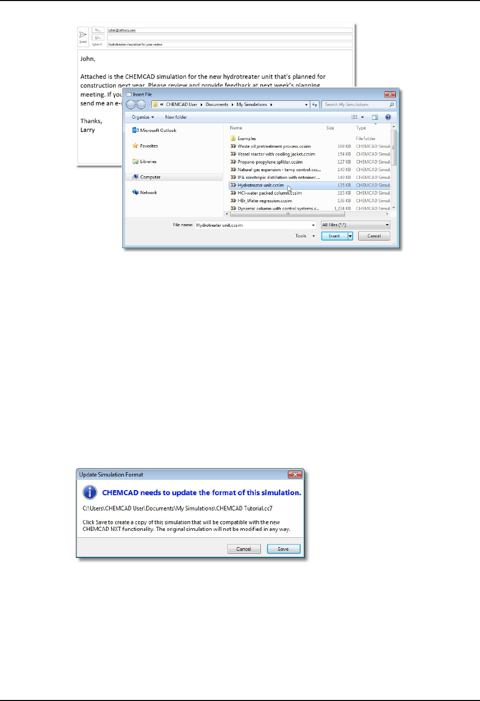
Working with Simulation Files
44 CHEMCAD User Guide
Figure 4-05: Adding a .ccsim file as an attachment in MS Outlook
Working with CHEMCAD Files from Previous Versions
You can use CHEMCAD NXT to open simulations that were originally created with
CHEMCAD 7. When you do this, the program creates a copy of the original
simulation, and makes that copy compatible with all CHEMCAD NXT functionality.
The flowsheet and simulation data in the copy are not altered in any way, and the
original file is left intact.
To update an existing CHEMCAD 7 simulation to CHEMCAD NXT format, click
the File tab, then click Open. In the Open dialog box, navigate to the correct
directory, select the simulation, and click Open. The Update Simulation Format
dialog box appears, informing you that you need to save a new copy of the
simulation.
Figure 4-06: Converting a CHEMCAD 7 file to .ccsim format
Click Save to bring up the Save As dialog box, where you can either keep or
change the file’s name and select a location for the new CHEMCAD NXT copy. Click
Save again to create and open the new file.
To import a simulation file that was created with CHEMCAD 6, you must first
open and save that file using CHEMCAD 7, and then bring the file into CHEMCAD
NXT using the method described here.

CHEMCAD User Guide 45
Chapter 5
Building and Using a Basic Simulation
The types of simulations you can create using CHEMCAD are many and varied, but
the basic procedure for creating a simulation can be broken down into the following
common steps:
1. Start a new simulation.
2. Specify engineering units for the simulation.
3. Select chemical components for the process.
4. Select K-value and enthalpy options for the process.
5. Draw the flowsheet with appropriate streams and unit operations.
6. Define the feed streams used in the process.
7. Enter specifications for the unit operations.
8. Run the simulation.
9. Review the results of the simulation.
Starting a New Simulation
When you launch CHEMCAD, you will see [Untitled] in the program’s title bar.
Click the File tab, then select Save Simulation As. In the Save As dialog box, specify
a name and location for the simulation file.
When you first install CHEMCAD, the default location for saving new
simulations is a folder called My Simulations, located within your computer’s My
Documents folder. You can save your new simulation to that folder, or to any

Building and Using a Basic Simulation
46 CHEMCAD User Guide
accessible directory on your computer or network. As you’ll notice in the Save As
dialog box, the file extension for CHEMCAD simulation files is .ccsim.
Specifying Engineering Units
To specify engineering units for this simulation, begin on the Home tab. In the Setup
group, click Engineering Units. This brings up the Engineering Units dialog box,
where you can select the units to be used for everything from time and temperature
to surface tension.
In this dialog, the available pre-selected sets of engineering units are called
profiles. The left side of the dialog box lists the built-in system profiles: English,
Common SI, Formal SI, and Metric. If the set of units you prefer to use doesn't
match any of these profiles, you can choose the best match and then manually select
different units as needed. To save your selections, click Apply. If you decide not to
save any changes, click Cancel to close the dialog.
If you do find yourself customizing your engineering unit selections, you can
save them as a user profile, which you can then easily apply to future simulations. To
do this, first set all the units the way you want them. Then at the top of the dialog,
click Save As > New Profile. Type a name for this profile and click OK to save your
settings. The name you entered will now appear on the left side of the dialog, under
the User Profiles heading.
For full details about how to manage user profiles for engineering units, see the
Engineering Units topic in the CHEMCAD help file.
Selecting Chemical Components
You can select chemical components for your simulation at any point while creating
the flowsheet, or you can wait until you’ve drawn the entire flowsheet before adding
components. Before you can run the simulation, you will need to list every
component involved in your chemical process, so that CHEMCAD can work with
those components’ properties.
These chemical components are pulled from CHEMCAD’s component database, a
master list of thousands of chemicals with their associated properties. When you’re
ready to add components for your simulation, first select the Home tab. Click Select
Components in the Setup group to open the Select Components dialog box.

Building and Using a Basic Simulation
CHEMCAD User Guide 47
Figure 5-01: The Select Components dialog box
The Available Components column lists the contents of the CHEMCAD
component database, while the Selected Components column lists the components
currently included in this simulation. For a new simulation, the Selected
Components list is empty at first.
Every chemical that will be part of the process, whether it’s a feed stream,
product, or utility, must be listed on this simulation’s component list.
Finding a Component
Because of the large number of components in the CHEMCAD component database,
scrolling up and down the list of available components can be time-consuming. To
find a specific component quickly, use the Search field at the bottom of the Select
Components dialog box.
Type the name of the chemical you want to find in the Search field. With each
letter that you type, CHEMCAD suggests possible matches in the Available
Components list. In the following example, typing the letters wa in the Search field
has highlighted the Water component.

Building and Using a Basic Simulation
48 CHEMCAD User Guide
Figure 5-02: Using the Search field to locate the Water component
Note that in some situations, the first result may not be the one you want. For
example, typing ethane in the Search field brings up the Methane component at
first. To see the next match for your text, click Next; continue clicking this button as
needed until you find the desired component.
The Search field accepts both text and numeric entries. By default, CHEMCAD
will search for your entry among all chemical names, chemical formulas, and
CHEMCAD database IDs; if you like, you can also search by CAS RN® number. To
turn any of these search options on or off, click the Options button below the Search
field. This brings up the Search Options dialog box, where you can specify which
data to include in your component searches.
Figure 5-03: Selecting which data to include in component searches
Note: You can add your own custom components to the CHEMCAD component
database. For more details about this feature, see Chapter 9, Customizing CHEMCAD.

Building and Using a Basic Simulation
CHEMCAD User Guide 49
Adding a Component
Once you’ve located the component you want in the Available Components list,
simply double-click the component to add it to the Selected Components list for your
simulation.
You can also select multiple components in the Available Components list and
then click the right arrow button, located between the two columns, to add all the
selected components to your simulation. To select multiple components, use
Windows’ standard selection methods of holding down [
SHIFT] to select contiguous
items or holding down [
CTRL] to select non-contiguous items.
Figure 5-04: Adding multiple components using the right arrow button
If you would like to duplicate the component list from an existing simulation,
click Copy From Another Simulation. In the resulting Open dialog box, navigate to
the desired simulation, select that simulation, and click Open. The Selected
Components list is now populated with the components used in the simulation you
selected; you can add or delete items to customize the list.
Changing the Order of Selected Components
When your Selected Components list for a simulation is particularly long, you may
find it helpful to place certain components at either the top or the bottom of the list.
You can add components in any order, and then move them around in the list as
needed.
To move a component to a new position in the Selected Components list, click
the component to select it and then:
• Click Top to move it to the first position on the list.
• Click Up to move it up one position.
• Click Down to move it down one position.
• Click Bottom to move it to the last position on the list.

Building and Using a Basic Simulation
50 CHEMCAD User Guide
Removing Items from the Selected Components List
To remove a single component from the Selected Components list, click the
component to select it and then click Delete in the bottom right area of the Select
Components dialog box.
To remove all components from the Selected Components list and begin again,
click Clear, just to the right of Delete. If you have changed your mind about adding
components at this time, you can simply click Cancel to back out of component
selection.
When you have added all the desired components to the Selected Components
list, click OK to load these components into the simulation and return to the main
CHEMCAD workspace.
Selecting K-value and Enthalpy Options
The first time you complete the Select Components dialog box, you’ll be taken to the
Thermodynamic Suggestions dialog box. At this point, you can either click Cancel to
skip this dialog and select thermodynamics manually, or enter parameters and click
OK to see which methods the program suggests.
Using the Thermodynamic Suggestions Dialog
Proper selection of thermodynamics is generally the most important step in a
process simulation. A poor thermodynamics selection may lead to unrealistic
simulation results.
With the Thermodynamic Suggestions dialog, CHEMCAD makes general
suggestions, based on your component list and the specified ranges for temperature
and pressure.
Selecting Components to Ignore
In the upper portion of the dialog, use the drop-down boxes to indicate any
components that CHEMCAD should not consider. This may affect the results for
model suggestion. For example, if you are using water as a coolant and your other
components are alkanes, the program will suggest UNIFAC. If you specify that
water should be ignored, the program will ignore water and select SRK.
Specifying Process Conditions
In the lower portion of the dialog, specify the approximate temperature and pressure
ranges for this process. Entering accurate information in these fields will help the
program return a more useful recommendation.
You can also specify a BIP data threshold—a minimum percentage of possible
binary interaction parameters (BIPs) which must be present in a BIP activity
coefficient model (NRTL, Wilson, etc.). Without BIPs, activity coefficient models
simplify to Raoult’s law.

Building and Using a Basic Simulation
CHEMCAD User Guide 51
How CHEMCAD Makes Thermodynamic Suggestions
The program follows a logic tree to choose a model. The logic tree assumes that all
your components are mixed in a vessel, with conditions falling into the specified
temperature and pressure ranges.
• If all components are hydrocarbons, CHEMCAD will likely suggest an
equation of state.
• If water is present, the program will likely select an activity coefficient model.
• If water and hydrocarbons are present, the likely suggestion will be UNIFAC.
• If water and strong electrolytes (HCl, NaOH, etc.) are detected, the program
will suggest electrolyte models.
Temperature and pressure range will affect the selection of model. If pressure is
high, CHEMCAD is more likely to suggest an equation of state. If pressure is
atmospheric and temperature is below the normal boiling point of all components,
the program may choose an activity coefficient model or ideal vapor pressure.
Should the results of the Thermodynamic Suggestions dialog be trusted
to make design decisions?
Use this dialog as a starting point for your decision. Proper selection of
thermodynamics is the engineer’s responsibility. Your simulation may call for the
use of a different thermodynamic model than what the program suggests.
Manually Selecting Thermodynamics Settings
When you complete the Thermodynamic Suggestions dialog (or simply click OK to
accept the default entries), you’ll see a pop-up message displaying the selected K-
value and enthalpy models for your simulation. Click OK again to bring up the
Thermodynamic Settings dialog, which enables you to set up thermodynamics for
your simulation manually.
If you’re happy with the current selections, or you would prefer to address these
settings later, you can click OK to close the dialog and return to the main
CHEMCAD workspace.
To return to the Thermodynamic Settings dialog at any time, start on the Home
tab and follow these steps:
1. Select Thermodynamic Settings in the Setup group.
2. This opens the Thermodynamic Settings dialog box. Start by determining,
based on your process knowledge, whether your system has two liquid
phases or a single liquid phase. In the Global K-value Model field, select a
method that can calculate the phase behavior relevant to your system.
3. Based on the specific circumstances of your process, make any needed
alterations to the options displayed on the K-value Models tab. Note that the

Building and Using a Basic Simulation
52 CHEMCAD User Guide
options appropriate to your selected K-value method are displayed in black,
while irrelevant options are displayed in gray.
Note: When you change the Global K-value Model selection, CHEMCAD
may automatically update the Global Enthalpy Model setting as
appropriate. If this happens, you will see a message on the K-value Models
tab. You can change the selected enthalpy model by making a new selection
in the Enthalpy Models tab.
4. Click the Enthalpy Models tab, select the most appropriate model in the
Global Enthalpy Model field, and make any other changes to the options on
this tab as needed for your process.
5. Click the Transport Properties tab and verify that the settings there are
appropriate for this simulation. Change any settings as needed and then click
OK to close the Thermodynamic Settings dialog box.
Drawing the Flowsheet
To create the flowsheet for your simulation, you’ll need to add the appropriate unit
operation icons to your workspace and connect those UnitOps to one another with
streams. This connected group of streams and UnitOps forms the basis for the
simulation.
Adding UnitOps
Start by adding UnitOp symbols for the equipment that will be part of your
simulation. The tools for adding UnitOps to a flowsheet are located in the Palette
pane, which by default displays on the right margin of the CHEMCAD window.
This pane offers specialized palettes for UnitOp categories such as Heat
Exchangers and Reactors, but the default palette view is All UnitOps, which displays
all the available UnitOp icons at once.
Note: If you do not at first see the Palette pane, it may have been turned off. To
restore this pane, click the View tab, then click Palette in the Show group. If the
pane is turned on but you only see the word Palette sideways in the upper right
corner of the screen, the pane is unpinned; see Chapter 3, The CHEMCAD
Interface, for information about pinning and unpinning panes.
To place a UnitOp icon on your flowsheet, follow these steps:
1. On the All UnitOps palette, find the appropriate UnitOp symbol for the
equipment you want to represent. If you are unsure about which UnitOp best
fits your purposes, you can see a brief pop-up description of any palette item
by hovering your mouse pointer over its symbol.

Building and Using a Basic Simulation
CHEMCAD User Guide 53
2. Click the symbol and drag it onto the workspace where you want to place the
UnitOp. When you release the mouse button, the UnitOp symbol appears
where you clicked.
Using Alternative UnitOp Symbols
Most CHEMCAD UnitOps have alternative symbols that you can use to represent
equipment on a flowsheet. You can use those symbols on a case-by-case basis, or
change a UnitOp’s default symbol to customize your palette.
Note: Items that are already in place on the flowsheet will not be affected when
you select a new default symbol for a UnitOp.
To view the symbols available for a given UnitOp, right-click the current symbol
on the palette. A subpalette will pop up, displaying all available symbols.
Figure 5-05: Viewing the subpalette for the Compressor UnitOp
From a subpalette, you can drag any symbol onto the flowsheet, just like the
symbols on the main palette. When you do this, the selected symbol appears on the
flowsheet and the subpalette automatically closes.
To change the default symbol for a UnitOp, first right-click to open the
subpalette, then hold down the [
CTRL] key and click the symbol you want to use.
After you do this, the symbol you selected appears on the main palette. You can
change the default icon for a UnitOp as often as you like.

Building and Using a Basic Simulation
54 CHEMCAD User Guide
Manipulating UnitOp Icons
After drawing a UnitOp symbol on a flowsheet, you can move, duplicate, resize, flip,
rotate, or delete the symbol as needed.
1. Click the UnitOp symbol so that you see its sizing handles (green boxes at
each side and at each corner). If you click a UnitOp and no handles appear,
try zooming in for a closer view.
2. Manipulate the UnitOp icon as needed:
• To move a UnitOp, click the center of the symbol and drag it to a new
location.
• To duplicate a UnitOp, right-click its symbol and select Copy. Then right-
click anywhere on the workspace and select Paste.
• To resize a UnitOp symbol, click any sizing handle and drag inward or
outward to achieve the desired size. It is recommended that you always
use the corner handles for resizing, as this will maintain the symbol’s
original shape.
• To flip a UnitOp symbol, right-click it and then select either Flip
Horizontal or Flip Vertical.
• To rotate a UnitOp symbol 90 degrees, right-click it and then select either
Rotate Clockwise or Rotate CounterCW.
• To delete a UnitOp, right-click its symbol and select Delete, or simply
press the [
DELETE] key on your keyboard.
UnitOp IDs
When you place UnitOps on a flowsheet, CHEMCAD assigns each one an ID
number that is unique within the simulation. The UnitOp number is a vital identifier
for the unit, as it is used in various reports and charts related to the simulation.
The UnitOp ID is displayed in an oval, easily distinguishable from the
rectangular boxes used to display Stream IDs.
Figure 5-06: A UnitOp symbol with its ID oval
The default position of a UnitOp ID is just above and to the left of the unit’s
flowsheet symbol. If you subsequently move the UnitOp symbol, its ID remains in
the same relative position.

Building and Using a Basic Simulation
CHEMCAD User Guide 55
In some situations, you may want to move a UnitOp ID from its default location.
To do this, click the UnitOp to highlight it, then move your mouse cursor over the
UnitOp ID oval. When you see the cursor change to a curved hand shape, click and
drag the ID oval to the desired location.
Figure 5-07: The hand cursor for moving a UnitOp ID (left), an ID being moved to the opposite
side of the UnitOp symbol, and the ID oval in its new location
UnitOp ID Ranges
When you place UnitOps on a flowsheet, CHEMCAD assigns each one a UnitOp ID
number that is unique within the simulation. The UnitOp ID number is an important
identifier for the unit, as it is used in various reports and charts related to the
simulation. By default, your UnitOps will be numbered, starting at 1, in the order in
which you create them; all types of equipment share the same pool of ID numbers.
If you want to group your UnitOps numerically by equipment type, you can use
the Starting IDs feature to accomplish this.
Click the Specification tab, then in the Simulation group, click Starting IDs.
This brings up the Stream and UnitOp Starting IDs dialog box. Here you will see
each type of UnitOp available in CHEMCAD, each with a default Starting ID setting
of 1. This means that any new UnitOp will be assigned an ID from the same number
pool—the next number (1 or greater) that has not yet been used in this simulation.
To set up separate ranges of numbers for different equipment types, you can edit
the values in the Starting ID column. For example, you could set the Heat Exchanger
value to 200, the Pump value to 300, the Pipe value to 400, and so on, using any
starting values that are meaningful to you. Any UnitOp type you don’t assign a
starting value will pull ID numbers from the main pool starting with 1, skipping any
numbers that are already assigned.
Click OK to put your selected starting IDs into effect.
UnitOp Names
In addition to the assigned ID, you can give a UnitOp a name, using up to 11
alphanumeric characters. This name appears in the UnitOps area of the CHEMCAD
Explorer pane, on certain reports, and optionally on the flowsheet with the UnitOp
ID.
To add a UnitOp name, right-click the UnitOp on the flowsheet and select Edit
Name; type the name in the resulting dialog box and click OK.

Building and Using a Basic Simulation
56 CHEMCAD User Guide
By default, a newly added UnitOp name will appear beneath the number in the
UnitOp ID box. To hide a single UnitOp’s name, right-click the UnitOp and clear the
check mark next to Show Name; simply check this menu item again to make the
UnitOp name visible.
To view or hide all UnitOp names on the flowsheet at once, click the View tab,
then in the Flowsheet group, either check or clear the Show UnitOp Names box.
Feed and Product Arrows
The first two items at the top of every built-in palette in CHEMCAD are the Feed
and Product arrows. You will need to place Feed and Product icons on the flowsheet
to represent the starting and ending points of feed and product streams,
respectively.
• The Feed icon must be placed at the start of any feed stream, i.e., any stream not
originating in a flowsheet UnitOp.
• The Product icon must be placed at the end of any product stream, i.e., any
stream not terminating in a flowsheet UnitOp.
For the color scheme called System Color, the Feed icons are red and the Product
icons are blue.
Note: Once a feed or product arrow is connected to a stream, you can double-
click the arrow to open the Edit Streams dialog for the associated stream.
Drawing and Connecting Streams
Before you can add a stream to a flowsheet, you must already have drawn the
UnitOps that the stream will connect. Follow these steps to add a stream:
1. Decide which outlet and inlet ports you will use to connect the two UnitOps
on the flowsheet. Each UnitOp icon displays its ports as dots: red for outlets
and blue for inlets.
2. Move the cursor to the red outlet port you’ve chosen, until you see the hand
cursor appear.
3. Click and drag toward the desired inlet on the downstream UnitOp. When
you see the cursor change to an anchor shape, and the inlet port outlined in
red, release the mouse button.

Building and Using a Basic Simulation
CHEMCAD User Guide 57
4. The stream will appear between the objects you have connected.
Note: You can also click and release at the outlet port, move the mouse
pointer wherever you like, and then click and release again when you reach
the desired inlet port. There is no need to hold the mouse button down the
entire time.
Choosing a Stream Route
When you draw a stream using the basic click-and-drag method described above,
CHEMCAD chooses a path for the stream. In some situations, you may want to
choose a deliberate route for your stream.
To do this, click the mouse as you move from outlet to inlet, wherever you want
the stream to make a turn. Each time you click, the stream freezes in place, and from
there you can make a 90° turn to either the left or the right. You can add as many
detours as you like to a stream before bringing it into a UnitOp inlet.
Rerouting a Stream
Even after you’ve completed your flowsheet and added detailed information about
your streams, you can still reroute a stream if needed. There are two ways to do this.
The first method is to move the existing stream around using its sizing handles.
When you click on a stream to select it, the stream line displays in green, and small
green sizing handles appear. Each stream turn will have a sizing box, as well as each
stream segment. You can click and drag any of these handles to move the adjacent
stream segment(s) to a new location.
If you click a corner sizing handle, you can move the two adjacent stream
segments in any direction; this often affects the position of other stream segments as
well. If you click a sizing handle in the middle of a stream segment, then you can
only move the segment left and right (for a vertical segment) or up and down (for a
horizontal segment).
The second method for rerouting a stream is to re-draw it entirely. To do this,
click the stream to select it, then right-click and select Reroute stream. The old
stream disappears, replaced by the beginning of a new stream originating at the
same outlet.
You can now click to create 90° turns, the same way you would with a new
stream, to route the stream exactly where you want it. After a stream is rerouted, it
retains all of the stream detail that you had previously entered.

Building and Using a Basic Simulation
58 CHEMCAD User Guide
Stream IDs
When you draw streams on your flowsheet, CHEMCAD assigns each one a stream
ID number that is unique within the simulation. The stream number is an important
identifier for the stream, as it is used in various reports and charts related to the
simulation.
The stream ID is displayed in a rectangular box, easily distinguishable from the
ovals used to display UnitOp IDs.
Figure 5-08: A stream ID box
When you draw a stream, the ID box is positioned on the longest stream
segment. If you subsequently move the flowsheet objects that contain the stream’s
end points, or otherwise change the path of the stream, the stream ID box will
change its position accordingly.
In some situations, you may want to move a stream ID box from its default
location. To do this, click the stream to highlight it, then move your mouse cursor
over the stream ID box. When you see the cursor change to a curved hand shape,
click and drag the ID box to the desired location.
Figure 5-09: The hand cursor for moving a stream ID box (left) and a stream ID box being moved
If you have manually placed a stream ID box, you might later want to restore it
to its default location on the stream. To do this, simply right-click the stream or the
ID box and select Reset ID Position. This returns the stream ID box to its automatic
placement on whichever stream segment is currently the longest.

Building and Using a Basic Simulation
CHEMCAD User Guide 59
Stream ID Ranges
By default, your streams will be numbered, starting at 1, in the order in which you
create them. If you want to create a series of streams with a separate range of ID
numbers from the rest of your simulation, you can use the Starting IDs feature to
accomplish this.
Click the Specification tab, then in the Simulation group, click Starting IDs.
This brings up the Stream and UnitOp Starting IDs dialog box. Scroll down to the
Stream option and click the right column. Enter the number that will be the start of
your separate stream ID pool and then click OK. If you later need to draw more
streams with ID numbers in the normal range, you can return to this dialog box and
reload the default setting.
For example, to draw a series of utility streams with ID numbers starting at 300,
you would set the stream starting ID option to 300 and draw the streams in question.
Those streams would be numbered 300, 301, 302, and so forth. After drawing all
your utility streams, you would then set the Stream ID option back to 1, so that the
next new stream in the main flowsheet would be assigned the next available stream
ID from the regular pool of numbers. You can reset the stream option number as
many times as needed while you create and edit your simulation.
Stream Names
In addition to the assigned stream ID, you can give a stream a name, using up to 11
alphanumeric characters. This name appears in the Edit Stream dialog, in the
Streams area of the CHEMCAD Explorer pane, on certain reports, and optionally on
the flowsheet with the stream ID.
To add a stream name, you can open the Edit Streams dialog and type in the
Stream Name field. Another way to add a name is to right-click the stream and
select Edit Name; type the name in the resulting dialog box and click OK.
By default, a newly added stream name will appear beneath the number in the
stream ID box. To hide a single stream’s name, right-click the stream and clear the
check mark next to Show Name; simply click this menu item again to make the
stream name visible.
To view or hide all stream names on the flowsheet at once, click the View tab,
then in the Flowsheet group, either check or clear the Show Stream Names box.
Stream Intersections
When streams cross on a flowsheet, a visual indicator can be helpful to show that the
streams do not interact with one another. You can set up a default size and shape to
show one stream “jumping” over another wherever two streams meet. By default, a
stream jump displays as a semicircle.
CHEMCAD offers several other options for stream intersections, including no
jump indicator and a dash to break one stream line as it crosses. The figure below
shows all of the available stream intersection options.

Building and Using a Basic Simulation
60 CHEMCAD User Guide
Figure 5-10: Stream intersection options (from left: None, Dash, Triangle, Trapezoid, Square,
and the default setting, Circle)
To select a stream intersection option for the current simulation, click the Drawing
tab, then in the Workspace group, click Stream Styles. In the Stream Styles dialog,
drop down the Style list under Intersections, and select an option. When you click
OK, any stream intersections already on your flowsheet will change to the new style;
any new intersections that occur will also use that style. This style will continue to be
used for new intersections, even after this simulation has been closed and re-opened.
To change the global style for stream intersections—that is, to set the default for
all future simulations created in your CHEMCAD installation—you can change the
setting in a different place. Click the File tab, then Preferences. In the Preferences
dialog, click Stream Styles in the left column. This brings up the same list of stream
intersection options, but when you select one and click OK, the chosen style will
become the global default for this CHEMCAD installation.
Note that you can also change the size of the stream jumps in both the local and
global settings for stream intersections. The default size is 48, which is well
proportioned for use with standard UnitOp sizes.
Defining Streams
At this point, the streams that you have drawn on your flowsheet are still just lines
with no data behind them. The next step is to edit these streams as needed,
populating them with composition data and other properties.
In most situations, the streams you’ll need to define will be the feed streams in
your process. Other types of streams, such as recycle cut streams, may also require
definition.
You can edit a single feed stream using any of these methods:
• Double-click the stream.
• Right-click the stream line and select Edit Stream.
• On the Home tab, in the Specification group, click Edit Streams. Enter the
stream number you want to edit and then click OK.
• On the Explorer’s Simulation tab, expand Flowsheet and then Streams,
right-click the stream in question, and select Edit Stream. (This is a useful
approach for especially large and complex flowsheets.)
To edit multiple streams at once, you can use the following methods:

Building and Using a Basic Simulation
CHEMCAD User Guide 61
• Hold down [SHIFT] and click to select multiple streams on the flowsheet, then
right-click and select Edit Stream.
• Click Edit Streams in the Home tab’s Specification group, then either type
the stream numbers into the Select Streams dialog box or click the streams on
the flowsheet to add them to the list. Click OK when finished.
• To edit all the feed streams in the flowsheet at once, click the Edit Streams
drop-down (Home tab, Specification group) and select Edit Feed Streams.
Similarly, to edit all the cut streams in the flowsheet, select Edit Cut Streams
from the same drop-down.
The Edit Streams dialog box displays with either a single column of data (for one
stream) or a column for each stream that you have selected. Use this dialog box to
specify properties for each feed stream listed.
Thermodynamic Properties
You must specify exactly two of the following three variables:
• Temperature
• Pressure
• Vapor fraction
CHEMCAD will calculate the third variable and enthalpy, based on the two
variables you specify and the thermodynamic method you’ve selected, once the
stream composition data has been entered.
Note: In the Edit Streams dialog box, the user-specified values for feed streams will
display in green, differentiating them from calculated values.
Stream Composition
To define the stream composition, you’ll need to specify a composition unit and the
amount of each component that is present in the stream.
Select a unit from the Comp unit drop-down list, and then based on that
selection, populate the field for each component with the appropriate amount,
percentage, or fraction.
For stream compositions expressed as a percentage or fraction, you can enter
values that do not total 100%. In this case, CHEMCAD will normalize the
composition to fractional values that total 1. To preview the normalized values that
CHEMCAD assigns to the components, click Flash.
Total Flow Properties
If the component flow engineering unit used for a stream is dimensionless (i.e., mole
fraction, weight fraction, or volume fraction), you must specify the following flow
properties:

Building and Using a Basic Simulation
62 CHEMCAD User Guide
• Total flow
• Total flow unit
If you enter composition amounts using quantitative flow units, CHEMCAD
calculates the total flow rate for you.
Specifying Equipment Parameters
Once you have specified the necessary stream properties for your simulation, the
next step is to enter specifications for the UnitOps. You can edit the parameters of a
UnitOp using any of the following methods:
• Double-click the UnitOp icon on the flowsheet.
• Click the UnitOp icon (or hold down [
SHIFT] and click to select multiple
UnitOp icons) and then click Edit UnitOps in the Home tab’s Specification
group.
• On the Explorer’s Simulation tab, expand Flowsheet and then UnitOps,
right-click the UnitOp in question, and select Edit UnitOp Data. (This is a
useful approach for especially large and complex flowsheets.)
The dialog box that displays when you go to edit a UnitOp’s specifications will
depend on the type of UnitOp. The Stream Mixer UnitOp, for example, has only one
specification that you can set, while the SCDS Distillation Column UnitOp has five
tabbed pages of detailed settings.
Figure 5-11: Two UnitOps that require very different amounts of input
The detailed information about the specifications for each type of UnitOp is
contained in the CHEMCAD Help system, which you can access from any
CHEMCAD screen by pressing the [
F1] key.
These specification screens do, however, have certain rules in common:
• Items with green text labels are required entries.
• All other entries are optional.
• Clicking OK saves your specification changes; clicking Cancel discards them.

Building and Using a Basic Simulation
CHEMCAD User Guide 63
After you click OK, CHEMCAD checks your data for internal consistency and
then returns errors or warnings as warranted. These items display in the Messages
pane in the CHEMCAD window.
Running the Simulation
Note: The steps for running a simulation are different if you are using CC-
DYNAMICS for dynamic calculation. See Chapter 7, Building and Using a Dynamic
Simulation, for information about setting up and running dynamic simulations.
Now that you’ve drawn the flowsheet and added detail to the streams and UnitOps
that make up the flowsheet, you can run the simulation. To do this, simply click Run
All in the Home tab’s Run group.
Figure 5-12: The Run All command
When you run a simulation, CHEMCAD calculates material and energy balances
throughout the entire flowsheet and returns any errors or warnings discovered in
the flowsheet. If the run completes successfully, a Run finished message appears at
the far left of the status bar, at the very bottom of the CHEMCAD window.
If the flowsheet run has converged, the message Flowsheet calculation has
converged will appear in a pop-up message window, as well as in the Messages pane.
The word Converged will also appear near the center of the status bar; this message
will continue to display until you make changes to the flowsheet or the simulation
models that could affect convergence, and it will reappear after each successfully
converged run.
For preliminary checks of individual UnitOps or groups of UnitOps, you can
click Run Selected instead of Run All; either highlight the relevant UnitOps on the
flowsheet before invoking this command or select them afterward in the Select
UnitOps dialog box. You can also right-click any UnitOp on the flowsheet and select
Run This UnitOp.
Reviewing the Results
After a simulation has run, you can call up any number of individual text-based
reports or graphical charts, either for on-screen viewing or for printing. Reports can
provide data on any single stream or UnitOp, or any group of streams or UnitOps, in
a steady-state or dynamic simulation. You can also request a consolidated report that
provides comprehensive data on the streams and UnitOps you select.
Note: CHEMCAD reports, plotting, and chart printing are covered in detail in
Chapter 8, Output and Reports.

Building and Using a Basic Simulation
64 CHEMCAD User Guide

CHEMCAD User Guide 65
Chapter 6
Using CHEMCAD for High-fidelity Modeling
Simulations created in CHEMCAD vary greatly in detail, from vague and conceptual
to extremely specific and realistic. Depending on the demands of your process and
what you’re trying to achieve with your simulation, you may work with what we
call low-fidelity modeling, high-fidelity modeling, or both.
This chapter addresses CHEMCAD’s capacity for high-fidelity modeling and
how to achieve a high level of realism with your UnitOps.
What is high-fidelity modeling?
With low-fidelity modeling, you specify what you want, or what you have observed,
and CHEMCAD makes its calculations based on the assumption that you can
achieve what you’ve specified. It’s common to specify observed properties such as
temperature and/or pressure coming out of a UnitOp, or component purity coming
out of a separation unit. Specifying temperature coming out of a heat exchanger is an
example of low-fidelity modeling.
High-fidelity modeling, on the other hand, requires that you enter numerous
extensive variables. CHEMCAD calculates the resulting conditions based on these
detailed entries. With high-fidelity modeling, you’re often required to specify
geometry-related variables for a UnitOp so that CHEMCAD can calculate precise
conditions at the equipment’s outlet.
Here’s the key distinction between low-fidelity and high-fidelity modeling in
CHEMCAD:
• Low-fidelity: You specify the desired results and CHEMCAD assumes that you
can achieve those results with the equipment you have.

Using CHEMCAD for High-fidelity Modeling
66 CHEMCAD User Guide
• High-fidelity: You specify energy and equipment parameters and CHEMCAD
calculates the actual results.
Criteria for High-fidelity Modeling
To take advantage of CHEMCAD’s high-fidelity modeling capabilities, you must
provide detailed specifications for your equipment. To do this, most UnitOps require
that you select a calculation mode that allows for entry of high-fidelity-caliber detail.
For example, if you have a pump that is set to the default mode of Specify outlet
pressure, you’ll get a low-fidelity result from this pump—that is, the simulation will
use the outlet pressure that you specify, but without consideration for the size of the
pump, the amount of fluid entering the pump, or inlet pressure.
If you switch the pump to Specify performance curve, a high-fidelity mode, you’ll
need to enter data points from the pump’s performance curve, either for a single
speed line or for multiple speed lines. Using this mode, CHEMCAD will calculate
the change of pressure head based on the performance data and the inlet volumetric
flow rate. This provides a realistic pressure increase for the actual pump that your
process uses.
Not every type of CHEMCAD UnitOp lends itself to high-fidelity modeling. The
following sections discuss various types of UnitOps that do offer high-fidelity
calculation modes, and provide some basic information about how to use those
modes.
Introduction to Equipment Sizing
Equipment sizing in CHEMCAD is optional. It entails using the Sizing tab
commands, generally after running a simulation, to calculate approximate sizes for
pipes, vessels, valves, orifices, and other equipment.
Figure 6-01: Commands for sizing various UnitOps, accessed via the Sizing tab
Equipment sizing can complement low-fidelity results, and often provides an
excellent starting point for high-fidelity modeling. You can use certain sizing results
as input for high-fidelity models of UnitOps in your simulation. Specifying
geometric parameters for UnitOps can help you obtain more realistic results.
Note that for low-fidelity modeling, sizing does not change converged flowsheet
results. Also, for some UnitOps, certain geometry parameters must be entered
regardless of the selected calculation mode.

Using CHEMCAD for High-fidelity Modeling
CHEMCAD User Guide 67
High-fidelity Modeling and Sizing for Common UnitOps
High-fidelity modeling does not apply to all CHEMCAD UnitOps. This section
summarizes those UnitOps for which you can use high-fidelity modeling, and
compares that approach for each UnitOp type to low-fidelity modeling. Where
applicable, UnitOp sizing is also discussed as it relates to low-fidelity versus high-
fidelity modeling of these UnitOp types.
Piping
You can use either low- or high-fidelity modeling for piping in your simulation.
Pipeline sizing is done based on the composition of a selected stream.
Low-fidelity
For low-fidelity modeling of piping, you are required to specify pipe diameter and
length in most modes; design modes that calculate diameter are the obvious
exception to this. The pressure drop through the pipe is calculated based on
diameter, length, and flow rate through the pipe.
Sizing
To perform sizing calculations, first click the Sizing tab. In the Flow group, click
Piping, and then select the relevant stream or streams. In the Pipe Sizing dialog box,
select a sizing option and click OK for line sizing results. You can use these results,
such as suggested pipe thickness and diameter, to specify geometry for a Pipe
UnitOp, or simply review them for the information you need.
Note: You can also click to select the relevant stream on the flowsheet (hold down
[SHIFT] to select multiple streams), then right-click and select Line Sizing to access
the Pipe Sizing dialog box.
Figure 6-02: Line sizing results from the Pipe Sizing dialog box

Using CHEMCAD for High-fidelity Modeling
68 CHEMCAD User Guide
High-fidelity
In high-fidelity piping models, Pipe UnitOps interact with Node UnitOps to balance
pressure and flow rates hydraulically among connected pieces of flow-based
equipment. Nodes must be placed on both sides of all Pipe UnitOps to be included
in hydraulic balance; pressure and flow constraints are set at the nodes, not in the
pipes.
A high-fidelity piping model can show changes in flow rate based on back
pressure where two pipes mix, whereas a low-fidelity model would simply assign
the lower of two specified pressures to the outlet without consideration for back
pressure.
Pumps, Compressors, and Expanders
You can create pump, compressor, and expander UnitOps using either low-fidelity
or high-fidelity modeling.
Low-fidelity
For these equipment types, CHEMCAD calculates power usage and thermal effects
on the fluid, based on specified output pressure or pressure increase. Other
parameters, such as efficiency, are optional but do affect results.
High-fidelity
To produce a high-fidelity model for these equipment types, you must select the
operation mode in which you specify performance curves—that is, pressure change
as a function of volumetric flow rate. This performance information is generally
available from the equipment vendor. Based on the volumetric flow entering the
UnitOp, CHEMCAD calculates outlet pressure.
As with piping, high-fidelity modeling for pumps, compressors, and expanders
can be used with nodes as part of a hydraulic flow balanced network.
Vessels and Tanks
You can add vessels and tanks to your simulations using high-fidelity modeling, or
perform limited approximation of these equipment types with low fidelity in steady
state. Sizing is available for certain types of vessels.
Low-fidelity
With low-fidelity modeling of a vessel or tank, a stream enters the Flash UnitOp and
separates into vapor and liquid; CHEMCAD does not consider hold-up or liquid
level in the tank. If you want to take a steady-state snapshot of the vessel, you can
manually adjust the flow rate and/or thermal conditions to make volumetric flow
rates match the volume of the vessel.
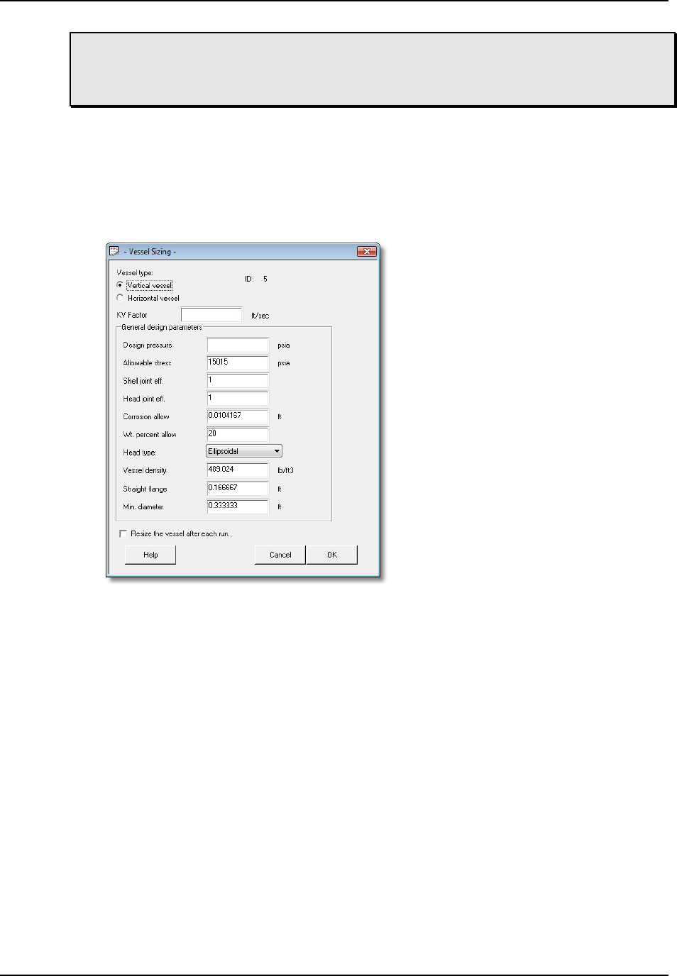
Using CHEMCAD for High-fidelity Modeling
CHEMCAD User Guide 69
Note: The Batch Tank UnitOp is specifically intended for use with the Batch
Distillation Column UnitOp. It does not represent a standard storage tank for
general purposes.
Sizing
To calculate sizing for a vessel, first select a Flash UnitOp, then click the Sizing tab.
In the Vessel group, click either LV Vessel (liquid-vapor vessel) or LLV Vessel
(liquid-liquid-vapor vessel), depending on your needs. In the resulting dialog boxes,
enter the appropriate values for your vessel and click OK.
Figure 6-03: Sizing a vessel in CHEMCAD
The results that CHEMCAD returns include basic vessel geometry such as height
and diameter.
You can also perform vessel sizing on a converged distillation column to
calculate geometry for a reflux drum or similar piece of equipment.
High-fidelity
You can perform high-fidelity modeling only on vessel reactors and dynamic
vessels, and only with a CC-DYNAMICS license (for dynamic vessels, a CC-SAFETY
NET license will suffice). If you specify the geometry of your vessel and use
CHEMCAD’s dynamics mode, you can study what happens in the vessel over time
as material is added or withdrawn.
Unlike simple flash vessels, vessel reactors and dynamic vessels do consider
hold-up, liquid level, and variable pressure over time.
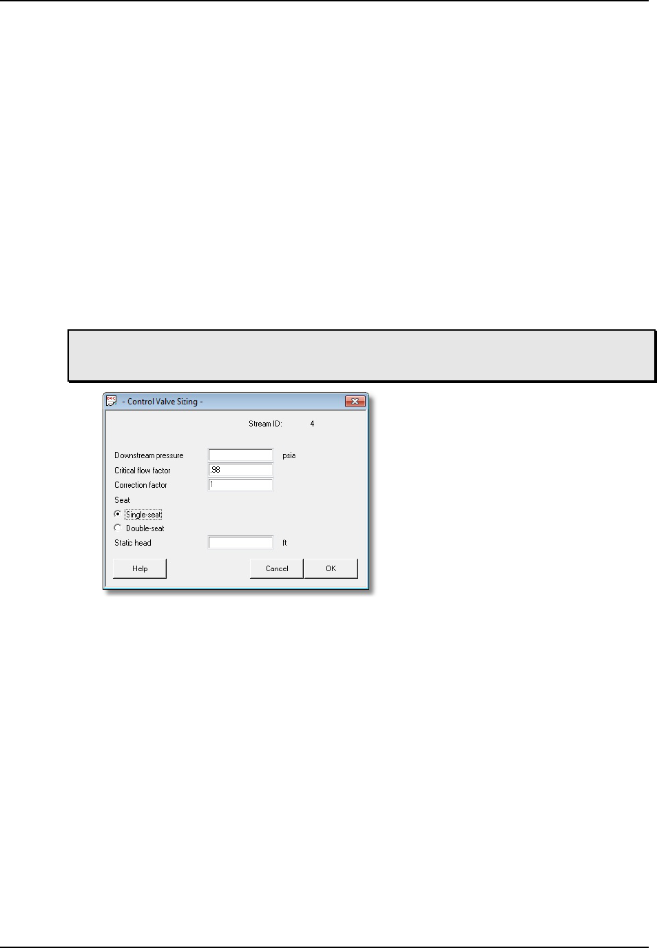
Using CHEMCAD for High-fidelity Modeling
70 CHEMCAD User Guide
Valves
Valve modeling in CHEMCAD can be either low-fidelity or high-fidelity. You can
size a control valve based on any flowsheet stream.
Low-fidelity
The Valve UnitOp is used for low-fidelity modeling of a valve. For this type of
UnitOp, you specify outlet pressure or pressure decrease through the valve.
Sizing
To size a control valve, first click the Sizing tab. In the Flow group, click Control
Valve, then select a stream. In the Control Valve Sizing dialog box, specify the outlet
pressure for the theoretical valve, and enter other specifications as appropriate.
When you click OK, CHEMCAD returns information such as capacity coefficient
(Cv) and valve size.
Note: You can also click to select the relevant stream on the flowsheet, then right-
click and select Control Valve Sizing to access the Control Valve Sizing dialog box.
Figure 6-04: The Control Valve Sizing dialog box
High-fidelity
The CVAL UnitOp is used for high-fidelity valve modeling. Decide which values
you will provide and which values CHEMCAD will calculate, and select the
appropriate operating mode in the Control Valve dialog box. Provide the valve’s Cv
value, and any other specifications as needed.
Control valves can be used with nodes as part of a hydraulic flow balanced
network.
Columns
Columns in CHEMCAD can be modeled as either low-fidelity or high-fidelity. You
can perform sizing on any converged column.

Using CHEMCAD for High-fidelity Modeling
CHEMCAD User Guide 71
Low-fidelity
For low-fidelity modeling of columns, use the Tower, Tower Plus, or SCDS UnitOps.
Specify ideal stages and the conditions at the reboiler and condenser, as applicable.
A low-fidelity column model does not consider mass transfer effects or column
internals.
Different column specifications can provide more realism without taking
geometry into account. Specifying top purity is a very low-fidelity model, while
specifying reflux ratio or condenser duty can bring your results closer to reality.
Sizing
After running your simulation, first select the UnitOp representing the distillation
column, then click the Sizing tab. In the Distillation group, click either Trays or
Packing, based on the type of column.
The resulting dialog boxes prompt you to enter information about your trays or
packing and the calculation methods you want to use for column sizing. You will
generally need to enter some geometry and hydraulic parameters to complete
column sizing.
Figure 6-05: Specifying high-level tray data for distillation column sizing

Using CHEMCAD for High-fidelity Modeling
72 CHEMCAD User Guide
Figure 6-06: Specifying detailed tray data
Based on flowsheet values and your sizing input, CHEMCAD returns column
geometry information such as height and diameter. It also provides hydraulic
performance information such as predicted amount of flooding.
High-fidelity
To perform high-fidelity modeling of a distillation column in steady state, use the
SCDS UnitOp and select either of the mass-transfer simulation models for the
column.
You will need to specify geometry for the column and choose a calculation
method for the selected mass-transfer model. CHEMCAD calculates column
performance based on your packing or tray specifications.
For columns, mass transfer-based modeling performs rigorous non-equilibrium
mixing of vapor and liquid, whereas low-fidelity modeling assumes ideal mixing.
To perform high-fidelity modeling of a distillation column in dynamics, specify
the geometry of the column and details about the control system. This dynamic
distillation can consider column hold-up and the effect of variables changing over
time.
Note: The Shortcut Column UnitOp is not a rigorous calculation model. Unless your
system satisfies the constant molar underflow assumption, you should consider
using a different type of distillation column.
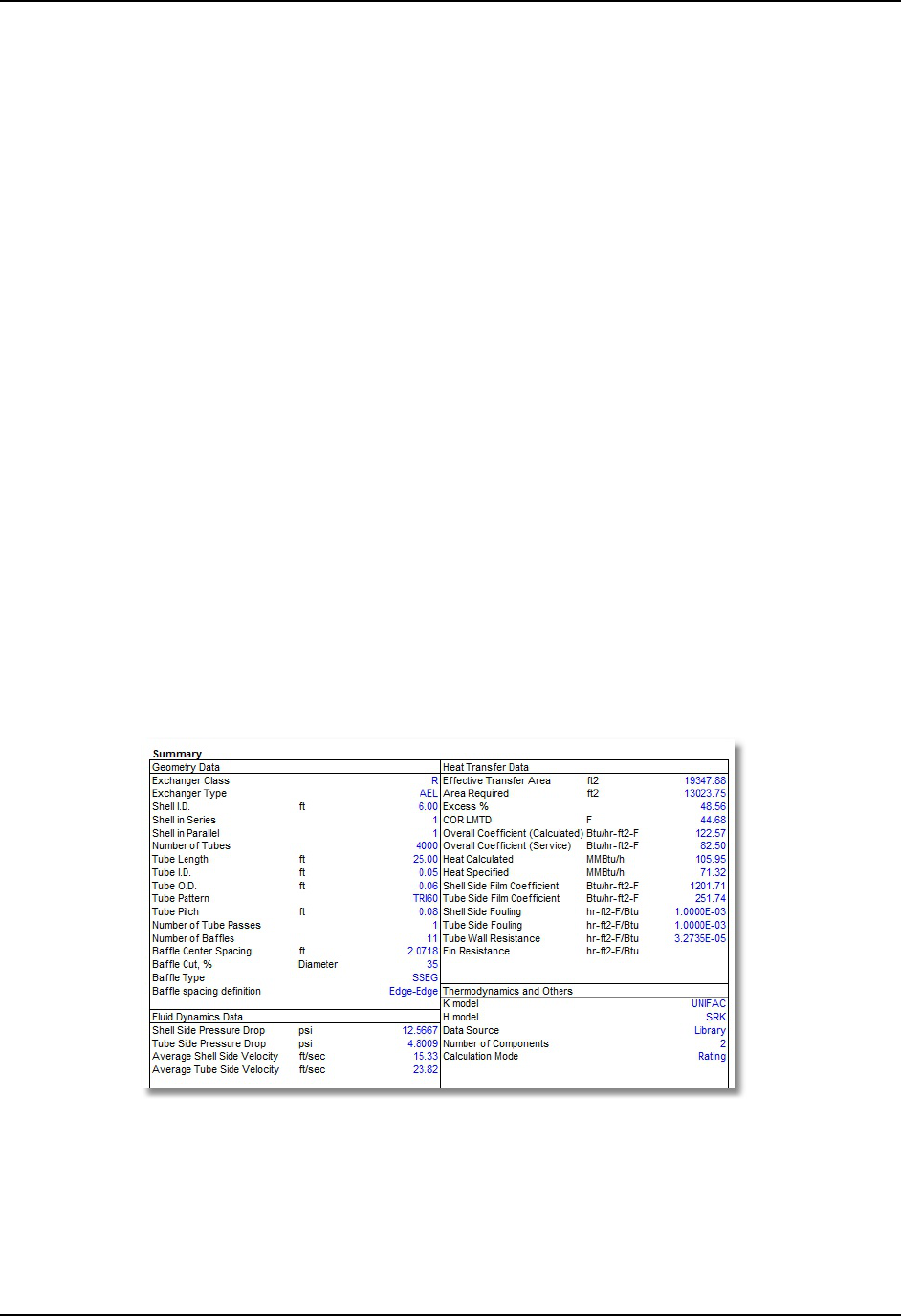
Using CHEMCAD for High-fidelity Modeling
CHEMCAD User Guide 73
Heat Exchangers
When specifying a heat exchanger in a simulation, you can use either low- or high-
fidelity modeling as well as sizing, depending on the type of heat exchanger
involved.
Low-fidelity
When creating a simulation, you can use a low-fidelity approach by simply
specifying the thermal conditions coming out of the exchanger. Specifying heat duty
instead of merely an outlet temperature brings your results closer to reality, but this
approach still doesn’t consider geometry.
Sizing
You can use the CC-THERM module for rigorous calculation of heat transfer
coefficient (U) based on heat exchanger geometry. In rating mode, CC-THERM
determines whether the user-specified heat exchanger is capable of the flowsheet
heat exchanger performance. In design mode, CC-THERM calculates an exchanger
design that is capable of the flowsheet performance.
High-fidelity
For some exchanger categories—specifically shell-and-tube and double-pipe—you
can use the rigorous CC-THERM model to calculate heat exchanger performance.
The flowsheet results are based on rigorously calculated U value and the specified
exchanger geometry. You can also determine approximate fouling of a unit if actual
outlet temperatures are known.
Figure 6-07: Heat exchanger summary report generated as an Excel worksheet

Using CHEMCAD for High-fidelity Modeling
74 CHEMCAD User Guide
Relief Devices
For relief devices, sizing is not necessarily distinct from low-fidelity modeling. To
model dynamic relief of a vessel, you can instead use high-fidelity modeling.
Low-fidelity
To model a steady-state snapshot of a relief device, first click the Sizing tab. In the
Safety group, click Relief Device to bring up the DIERS for Relief Device Sizing
dialog. Here you can specify a rating or design mode and select the appropriate
options for your relief scenario. When you click OK, CHEMCAD returns a relief
device calculation summary.
High-fidelity
If you select the Rigorous integral analysis design method when sizing a relief device,
you will obtain a results based upon the changing latent heat of the liquid as it
changes over time.
Figure 6-08: Selecting the rigorous integral analysis method for relief device design
You can also perform high-fidelity relief device modeling for the Vessel Reactor
and Dynamic Vessel UnitOps. You can specify the relief device nozzle area, as well
as other specifications for your relief scenario. This enables you to study the dynamic
relief of the vessel.

Using CHEMCAD for High-fidelity Modeling
CHEMCAD User Guide 75
Licensing Considerations for High-fidelity Modeling
To use the heat exchanger sizing functionality, you must have a valid license for the
CC-THERM module of CHEMCAD. To use vessel reactors, you’ll need a valid
license for the CC-DYNAMICS module. For dynamic vessels, a license for either CC-
DYNAMICS or CC-SAFETY NET is required.
Each of these modules is licensed independently. To view or change the
disposition of your various product licenses, see the CHEMCAD License Monitor
screen (File tab, then Licensing).
If you don’t currently have access to the heat exchanger sizing or dynamics
features and want to add any of these modules to your installation of CHEMCAD,
contact the person within your organization who handles software licensing, or if
appropriate, you can contact Chemstations or a CHEMCAD distributor directly. For
a complete list of Chemstations contacts worldwide, see our website
(www.chemstations.com).

Using CHEMCAD for High-fidelity Modeling
76 CHEMCAD User Guide

CHEMCAD User Guide 77
Chapter 7
Building and Using a Dynamic Simulation
While steady-state modeling can provide all the information you need for many
purposes, it’s often informative to look closely at the changes over time that affect
your streams and equipment. CHEMCAD’s CC-DYNAMICS module makes it
possible to simulate a process over time.
What do we mean by dynamics?
We use the term dynamics to describe modeling a chemical process over a set period
of time. During the course of a real-world chemical process, factors such as utility
temperature, feed composition, and liquid levels tend to change. Modeling the
response of your process to these changes can help you understand and predict what
happens with your process over time.
Given a flowsheet, a length of time to run, and the calculation interval to use,
CHEMCAD can return detailed results that take into account these types of changes.
The program can consider the material holdup within process equipment such as
tanks, reactors, and pipes. It also enables you to model control systems such as PID
controllers.
Licensing Considerations
To use the functionality described in this chapter, you must have a valid license for
the CC-DYNAMICS module of CHEMCAD. To view or change the disposition of
your CC-DYNAMICS product license, see the CHEMCAD License Monitor screen
(File tab, then Licensing).

Building and Using a Dynamic Simulation
78 CHEMCAD User Guide
If you don’t currently have access to the dynamics features and want to add CC-
DYNAMICS to your installation of CHEMCAD, contact the person within your
organization who handles software licensing, or if appropriate, contact Chemstations
or a CHEMCAD distributor directly. For a complete list of Chemstations contacts
and CHEMCAD distributors for all parts of the globe, see our website
(www.chemstations.com).
Additional Input for Dynamic Operation
Before you create a dynamic simulation, you’ll need to gather the relevant
information about your UnitOps and streams, as you would with any simulation. In
addition, you need to be able to answer the following dynamics-specific questions:
• How long will the simulation run?
• What will be the interval (delta time/step size) between calculations?
• What is the change that you want to study over time?
• If applicable, what is the initial composition and charge of any dynamic
vessels or vessel reactors?
• Which streams or UnitOps will be recorded for later analysis?
The basic steps for a dynamic simulation are largely the same as those for a
steady-state simulation, with a few vital differences:
1. Create a new simulation.
2. Select engineering units.
3. Select components.
4. Select thermodynamic options.
5. Draw the flowsheet.
6. Specify feed streams and initial stream conditions.
7. Set specifications for UnitOps.
8. Run the simulation in steady state to obtain time-zero values.
9. Switch the simulation to dynamics.
10. Specify dynamics settings, such as run time and initial charge(s), and indicate
which streams and/or UnitOps to record.
11. Reset the simulation to its initial state.
12. Run the simulation in dynamics.
13. Review the results.
14. Re-run or extend the simulation as needed.
15. Generate charts and reports as needed.

Building and Using a Dynamic Simulation
CHEMCAD User Guide 79
Before you start working on a dynamic simulation, it’s important to have as
much information about your process as possible, a clear idea of what you want to
find out, and a strategy for producing the results you need.
Strategies for Dynamic Simulations
When you start planning a dynamic simulation, it’s vital that you know what
question or questions you are trying to answer. To get useful, informative results,
you should start with a simple question and then refine the simulation and run it
again.
For example, to discover how heat affects a vessel’s temperature over time, you
might start by applying constant heat to the vessel for the duration of your dynamic
simulation. You can then save a copy of that simulation, change it to use variable
heat, and review the results to see how they differ from the original. Based on that
second simulation, you can make another copy, and this time try variable heat with a
control system to attempt to maintain a consistent temperature. Each of these
dynamic simulations would bring you closer to what you want to discover. Each
subsequent simulation requires more information from you to run and return the
results you want.
While there is no requirement that you approach dynamics problems this way,
it’s a sound practice that will save you time and frustration in the long run.
Setting up Dynamic Operation
Before you can run a dynamic simulation, you need to provide parameters such as
run time and step size. First, however, you must activate CHEMCAD’s dynamics
mode.
Switching to Dynamics
To switch to dynamics, first open the simulation. On the Home tab, simply click the
word Dynamic in the Run group.
Figure 7-01: Switching to dynamics
After you do this, you’ll notice that a few things have changed on the CHEMCAD
screen:
• The status bar at the bottom of the main CHEMCAD window changes. A few
inches from the left edge of the screen, instead of the words Steady State,
you’ll now see DTime and a time counter displaying the number of minutes
your simulation has run. Before you run the simulation, the DTime setting
displays 0:00 min.

Building and Using a Dynamic Simulation
80 CHEMCAD User Guide
• The steady-state commands on the Home tab’s Run group are now
unavailable, and the dynamics commands are activated.
Setting the Run Time
The next step is to set the run time for the simulation. First decide whether your run
will require a single step or multiple steps.
A step in this case refers to a time period during which CHEMCAD will capture
data from the simulation at uniform intervals. For example, you might set up a
single-step dynamic run of 60 minutes, with a step size of one minute, for a total of
60 data points for the run. If this is all that you need to do, your run can be
accomplished in a single step.
If, on the other hand, you need to run your process for 60 minutes capturing data
at one-minute intervals, and then switch to capturing data every 30 seconds for the
next 20 minutes, you’ll need to use two steps. If you want to record data every five
minutes for the first hour, every minute for the second hour, and every 30 seconds
for the third hour, you’ll need to use three steps.
The step size that you select will have an impact on the accuracy of the results
and the speed of the calculation. Smaller time steps produce more precise results, but
also require more time to make the run. Smaller isn’t always better, however, as
extremely small time steps can lead to significant round-off error.
Once you know how many steps you need to use and what your data-capture
interval will be for each step, follow these steps to set the run time parameters:
1. In the Home tab’s Run group, click Set Run Time. This brings up the
Dynamic Run Time Schedule dialog box.
Figure 7-02: The General tab on the Dynamic Run Time Schedule dialog box
2. On the General tab, set the number of operation steps you plan to use, or
leave the default setting of 1. The maximum number of steps that you can
specify is 10.
Note: When you initially set up dynamics for a simulation, the Current time display
field on this tab will be empty. After the simulation has run, this field displays the
total time of a completed run, or the current time of an interrupted run.

Building and Using a Dynamic Simulation
CHEMCAD User Guide 81
3. Now click the Step 1 tab and specify the parameters for this portion of the
dynamic run. Enter the total time for this dynamic step in the Run time field,
and the interval in minutes in the Step size field.
Figure 7-03: The Step 1 tab on the Dynamic Run Time Schedule dialog box
4. If you have other steps to specify, click each tab in turn and enter the Run
time and Step size information.
5. When you have specified all steps, click OK to return to the main
CHEMCAD workspace.
The Dynamic Run Time Schedule dialog box also allows for conditions other
than time to determine the duration of a dynamic operation step. If you select
Stream or Equipment instead of the default Time option, you can specify a stream
or UnitOp parameter that will trigger the end of this step, if that parameter is
reached before the step’s run time is up.
Selecting Streams and UnitOps
Now that you have specified how long your dynamic process will run, you need to
tell CHEMCAD what stream and UnitOp data to record during the run.
1. On the Home tab, in the Run group, click the Set Run Time drop-down and
select Record Streams.
2. In the Record Streams dialog box, do one of the following:
• Check the Select streams from flowsheet box, click OK, and then use the
mouse to add streams to the Select Streams dialog box.
• Type the numbers of the streams you want to record in the ID boxes.

Building and Using a Dynamic Simulation
82 CHEMCAD User Guide
Figure 7-04: The Record Streams dialog box
3. When you have selected all the streams you want to record, click OK to
return to the main workspace.
4. Now click the Set Run Time drop-down again, and this time select Record
UnitOps. In the Record UnitOps dialog box, select UnitOps in the same way
that you selected streams in step 2.
5. Click OK to return to the main CHEMCAD workspace.
Note: In both the Record Streams and Record UnitOps dialog boxes, you can use
the Chart check boxes to include selected items in a real-time chart. Selecting
items for runtime plotting leads to another dialog box (either Dynamic Stream
Chart Options or Dynamic Equipment Chart Options), where you can select
chart specifics for each stream or UnitOp. It is recommended that you use
runtime plotting in moderation, as too many streams and UnitOps can become
visually confusing and slow down calculations considerably.
6. Before proceeding, click Save in the Quick Access Toolbar to ensure that the
current settings are used as the simulation’s initial state.
Initial State Settings
In addition to the options for setting up and running a dynamic simulation, the
Home tab’s Run group offers two other dynamic commands: Save as Initial State
and Reset to Initial State. It’s important to understand what these commands do
before you begin to work with dynamic simulations.
Save As Initial State
The Save as Initial State command sets the current conditions of the dynamic run as
the new initial state. It discards all parameters from the previous initial state, and
makes it impossible to recover the previous initial state data.

Building and Using a Dynamic Simulation
CHEMCAD User Guide 83
An example of a dynamic run can illustrate the usefulness of this command.
Suppose that you run a simulation for five minutes and the temperature in a vessel
increases from 50 °C to 70 °C. You decide that 70 °C is a better starting point for this
vessel, and you want to capture all the other values that correspond to that
temperature in this vessel. You can achieve this by saving the current conditions as
the initial state.
To do this, click the drop-down arrow to the right of the Reset to Initial State
command, then select Save as Initial State. You will see a message warning you that
you will lose the original state conditions if you continue. If you are prepared to do
this, click Yes. For our example, this would mean losing the first five minutes of your
previous run, along with the 50 °C starting temperature for the vessel.
After you save a new initial state, the Run from Initial State and Reset to Initial
State commands both reference your new initial state settings.
Reset to Initial State
In a dynamic simulation, you can change stream and UnitOp specifications only
when the dynamic time is set to zero. During or after a run, if you attempt to edit the
specification dialog box for a UnitOp, you will find the OK button disabled and a
message instructing you to restore the simulation to its initial state.
Figure 7-06: A UnitOp specification dialog box after a dynamic run
To return the simulation to its initial state—also known as time zero—simply click
Reset to Initial State.
Note: An advanced feature to allow specification editing at any time is available, but
should be used with extreme caution to avoid confusion and unintended results.
This feature is controlled by a check box on the Convergence Parameters dialog box.
Running a Dynamic Simulation
Now that you have set the run time and recording parameters, you can run the
simulation. When you run a dynamic simulation in CHEMCAD, a calculation of the
entire flowsheet runs for each step in the time range that you select.

Building and Using a Dynamic Simulation
84 CHEMCAD User Guide
In dynamics mode, you have three options for running a simulation: run from
the simulation’s initial state, run from the simulation’s current state, or manually
advance the simulation one interval at a time.
Note: At any point during a dynamic run, you can press the [ESC] key on your
keyboard to stop the run after the current calculation. When you do this, you will see
a Program interrupted message. Click OK to close the message box, and then either
inspect your run results or select a run command to continue.
Run from Initial State
This option resets the flowsheet to its initial conditions and begins the dynamic
simulation. When you run a simulation this way, all results from previous
simulations are discarded.
To choose this option, simply click Run from Initial State in the Home tab’s Run
group. This is the default dynamic run mode each time you open CHEMCAD.
Run from Current State
When you use this option, the dynamic run begins from the current conditions.
Those conditions might be the initial state of the flowsheet, the end of a previous
run, or the middle of an interrupted run. Selecting this option continues the
simulation from the current state, i.e., from the last calculated result.
You can use this option only when some calculations remain to be run. This
means that unless you have interrupted the run using [
ESC] or the step-by-step
method described in the next section, you must schedule one or more additional
steps using the Set Run Time command before continuing.
To run the simulation starting from current conditions, click the Run from Initial
State drop-down (Home tab, Run group) and select Run from Current State.
Run One Step at a Time
If you want to get a detailed view of your dynamic run as it unfolds, you can choose
to run one interval at a time. With this option, the dynamic run will stop after each
discrete time step. To run the next time step, you will need to either direct
CHEMCAD to run the next step or use the Run from Current State command.
To use this frame-by-frame approach to dynamics, click the Run from Initial
State drop-down (Home tab, Run group) and select Run One Step.
Figure 7-05: Selecting the command to run one interval in a dynamic simulation

Building and Using a Dynamic Simulation
CHEMCAD User Guide 85
Output from Dynamic Simulations
The results from dynamic simulations are markedly different from those produced
by steady-state simulations, primarily in that they record data trends over time
instead of a static snapshot of a fixed process. With dynamic simulations,
comparisons of slightly different process specifications, and of the same process at
different points during a run, can be very useful.
For this reason, you may find that graphical reports provide the most useful
information when you’re working with dynamic simulations. CHEMCAD provides
a series of dynamics charting options to meet this need; you can also generate
various text-based reports, and view calculated flowsheet values at any point during
a dynamic run or after a run is complete.
Reviewing the Flowsheet Specifications
A snapshot of flowsheet values from a dynamic run doesn’t provide as much value
as it would for a steady-state run, but it can come in handy in many situations.
After running a dynamic simulation, you can view the data behind any
flowsheet stream or UnitOp to see the effects of the run calculations. Double-click
any stream or UnitOp on the flowsheet to review its end-of-run values.
You can also stop to review flowsheet data in the middle of a run, either by using
the Run One Step option or by pressing [
ESC] to pause a run. While the run is
stopped, you can click the flowsheet tab and then double-click any stream or UnitOp
to review its current values. To resume running after pressing [
ESC], click Run from
Current State on the Home tab.
Plotting Dynamic Results
Dynamic charts display selected values over time. You can plot the results of
dynamic simulations using the Charts drop-down gallery on the Home tab. The
following dynamic charts are available:
• Stream History: This chart displays selected stream properties from any
recorded stream.
• UnitOp History: This chart displays selected UnitOp parameters from any
recorded UnitOp.
• Column History: This chart displays selected values for a dynamic column,
including composition of trays, distillate, and bottoms.
• Vessel Reactor: This chart displays selected values for a Vessel Reactor
UnitOp, including composition of the contents over time.
• Dynamic Vessel: This chart displays selected values for a Dynamic Vessel
UnitOp, including composition of the contents over time.
• Batch Column: This chart displays values for a Batch Column UnitOp,
which requires a license for the CC-BATCH module.

Building and Using a Dynamic Simulation
86 CHEMCAD User Guide
Note: For the Stream History and UnitOp History charts, be sure to record the
streams and UnitOps that you want to study. You can only request these charts for
recorded streams or UnitOps.
Text-based Dynamic Reports
Based on the graphical results of your dynamic simulation run, you may decide to
make changes to your process, run parameters, or both, and then re-run the
simulation. When you have fine-tuned your simulation and obtained satisfactory
results, you can view those results in tabular form, for a more detailed look at exact
values.
To access text-based dynamic reports, click Reports on the Home tab and then
select one of the following reports from the Dynamic section of the gallery:
• Stream History: This report provides stream histories for a specific stream
that you select, based on the interval that you specify and including the
compositions, components, and stream properties that you select.
• UnitOp History: This report provides detailed information about a dynamic
UnitOp in the simulation, based on the interval that you specify and
including the UnitOp parameters that you select.
• Column History: This report provides dynamic column results for a selected
column. The Dynamic Column: Print Options dialog box offers the most
relevant items for dynamic column reporting.
Note: For the Stream History and UnitOp History reports, be sure to record the
streams and UnitOps that you want to study. You can only request these reports for
recorded streams or UnitOps.

CHEMCAD User Guide 87
Chapter 8
Output and Reports
One of CHEMCAD’s greatest strengths is its capacity to provide detailed,
customized information about equipment, streams, and processes. The program can
display a customizable snapshot of current data for any stream or UnitOp at any
time. You can also create custom reports, spec sheets, and databoxes for process flow
diagrams, and you can view data in the most appropriate chart or report format.
The charts and reports described in this chapter, along with the tools to
customize and format your simulation data, are all accessible from the Home tab,
using commands found in the Results group.
Figure 8-01: The Results group on the Home tab
The Basics: Generating Individual Charts and Reports
CHEMCAD makes it easy to generate a wide range of data charts and reports that
reflect the current state of your process simulation.
Clicking the drop-down arrow for either Charts or Reports brings up a gallery
view, displaying all the available chart or report selections. When a gallery is open,
you can point the mouse to any item to see a pop-up description of that chart or
report. To proceed, simply click the item you want.

Output and Reports
88 CHEMCAD User Guide
When you make a valid selection, CHEMCAD brings up a dialog box where you
can specify what to include in the requested chart or report. (If you choose a
selection that is not valid—for example, a chart type that is not compatible with your
current thermodynamic settings—you will see a message box explaining the error.)
After you specify the parameters for the chart or report, the results will display.
Charts and reports always display in their own tabs on the main CHEMCAD
workspace. Whenever a chart or report tab is selected, the ribbon displays
commands specific to charts or reports, respectively.
Note that there are also large icons above both the Charts and Reports
commands. When you first launch CHEMCAD, the icons displayed match the first
items in the respective galleries. When you select a different chart or report from a
gallery, you will see that item’s icon display on the command ribbon. If the next
chart or report you want to generate next is the same as your last selection, you can
simply click the icon to choose that item without opening the gallery. This can save
time whenever you find yourself generating the same chart or report repeatedly.
Figure 8-02: Icons above the Charts and Reports drop-down commands: defaults (left) and
examples of “last used” items (right)
The Charts Gallery
CHEMCAD offers a wide variety of charts—reports in graphical format—that you
can view onscreen or print for review. The Charts gallery displays the available
charts in groups according to their type or purpose.
Depending on the type of chart you select, you may need to specify relevant
streams or UnitOps or select other options in a dialog box before the chart can be
generated. Detailed information about chart generation options is available in the
CHEMCAD help system, which you can access by clicking a dialog’s Help button.
The available charts are listed and described below, according to the group
headings displayed in the Charts gallery.
Thermodynamic
CHEMCAD offers several charts that relate specifically to a simulation’s selected
components and thermodynamic options. To access any of these items, click Charts
to view the gallery, then select the appropriate item under the Thermodynamic
heading.

Output and Reports
CHEMCAD User Guide 89
TPXY
This selection generates vapor-liquid equilibrium curves between any two
components, with an optional third component. You can include TPXY, TXY, activity
coefficient, and fugacity coefficient curves.
Binary LLE
This selection generates liquid-liquid equilibrium curves between any two
components.
Binodal Chart
This selection generates a ternary phase diagram showing the distribution of three
selected components in two liquid phases, including tie lines and plait point.
Residue Curves
This selection generates and plots a graphical display of distillation zones,
azeotropes, and residue curves associated with a user-specified ternary mixture.
Binodal/Residue Curves
This selection creates a plot that combines the curves from a binodal plot and a
residue curve plot. This is useful when working with heterogeneous azeotropic
distillation.
Binary SLE
This selection displays solid-liquid equilibrium curves for binary mixtures.
Stream
CHEMCAD offers several charts that display data for selected streams on a
flowsheet. To access any of these items, click Charts to view the gallery, then select
the appropriate item under the Stream heading.
For any of these charts, you can choose the streams to include by typing in their
ID numbers in the Select Streams dialog; click the streams on the flowsheet to add
them to the stream ID list; or use All Streams, Feed Streams, Product Streams, or
Cut Streams to add groups of streams with a single click.
Stream Properties
This selection plots one selected stream property for any or all streams on the
flowsheet.
Phase Envelopes
This selection plots a phase envelope for a selected stream, highlighting the critical
point of the mixture. This chart can include plots at vapor fractions other than 0
(bubble point curve) and 1 (dew point curve).

Output and Reports
90 CHEMCAD User Guide
Petroleum Assay
This selection displays a chart of one or more distillation curves for a stream.
UnitOp
CHEMCAD offers several charts that display data for a single UnitOp. To access any
of these items, click Charts to view the gallery, then select the appropriate item
under the UnitOp heading.
Column Profiles
This selection plots compositions, temperature, and flow profiles for distillation
columns.
Heat Curves
This selection plots heating and cooling curves for a selected heat exchanger.
Composite Curves
This selection plots composite heat curves for the entire flowsheet, as well as
optional heat curves for individual UnitOps.
Plug Flow Reactor Profile
This selection plots the temperature or composition profiles along the axial length of
a kinetic plug flow reactor.
Pipe Profile
This selection plots fluid properties for pipe UnitOps along the axial length of the
pipe. This chart requires that the pipe contain multiple segments.
Controller Convergence
For controllers that have not converged, this chart enables you to diagnose the
controller behavior that is preventing convergence. The chart shows how the
controller error function changes with iteration.
Dynamic
CHEMCAD offers a series of charts for use with dynamic, or non-steady-state,
operations. (For more on dynamic process simulation, see Chapter 7, Building and
Using a Dynamic Simulation).
To access any of these charts, click the Charts gallery, then select the appropriate
item under the Dynamic heading.
Stream History
This chart displays stream data recorded over the course of a dynamic run. Before
requesting this chart, you must first use the Record Streams command to select
streams to include, and then run the dynamic simulation.

Output and Reports
CHEMCAD User Guide 91
UnitOp History
This chart displays UnitOp data recorded over the course of a dynamic run. Before
requesting this chart, you must first use the Record UnitOps command to select
UnitOps to include, and then run the dynamic simulation.
Column History
This chart displays selected data for a single dynamic run of a column. Note that in
the Dynamic Column Chart Options dialog, if you choose to plot a variable for a
specific stage, that stage must have been recorded during the dynamic run as part of
the column’s specifications.
Vessel Reactor
This chart displays selected data over time for a single dynamic run of a Vessel
Reactor UnitOp. In the Vessel Reactor Chart Options dialog, you can select various
equipment parameters to chart, and choose whether to include reactor composition
over time.
Dynamic Vessel
This chart displays selected data over time for a single dynamic run of a Dynamic
Vessel UnitOp. Composition over time can be displayed or excluded, and you can
single out a specific phase to appear on the chart.
Batch Column
This chart displays selected data over time for a single run of a Batch Distillation
UnitOp. In the Batch Column Chart Options dialog, you can choose to plot all
operation steps or specify a single step to include.
User
If you have customized CHEMCAD using VBA, C++, or other programming
languages, you can save chart data into a text file and use this feature to display that
data as a curve.
To access this feature, click Charts and then select User-specified at the bottom
of the gallery. This brings up a message box that provides instructions on how to
format the text file. Click OK to continue to an Open dialog box, where you can
select the text file you want to use. When you click Open, the curve is plotted and
displayed.
Chart Tab Commands
After you request a chart, CHEMCAD generates the graphic and displays it in a
separate workspace tab. If multiple charts were generated, each chart displays in its
own tab. The simulation tab, all open chart tabs, and all open report tabs can be seen
and selected at the bottom of the main workspace.

Output and Reports
92 CHEMCAD User Guide
Whenever you are viewing a chart, the top of the CHEMCAD window displays
the Chart tab, beneath the title Charting Tools. On this tab, you will find specialized
commands that control the appearance of the current chart’s data and labels.
The Chart tab commands are described below.
Edit Group
Close All Charts
This command closes the current chart, along with every other chart that is currently
open. To close only the current chart, simply click the x on the chart’s tab at the
bottom of the workspace.
Save
This command enables you to save a chart within the simulation. Saved charts are
listed in the Explorer pane under Saved Charts, where you can re-open them for
later reference. This command is also used to save any changes you may have made
to a re-opened chart.
Save As
This command is much like Save, except that it brings up a Save As dialog that
requires you to provide a name for the chart that you are saving. You can also use it
to make a copy of a re-opened chart under a different name, so that you can change
the new copy’s settings or labels while keeping the original copy.
Export Chart
You can use this command to export the current chart data, either as an Excel .csv
file or as a semicolon-delimited table.
User Series
The User Series feature enables you to add a data point or series of points to an open
chart in a CHEMCAD simulation. This information appears alongside the chart’s
calculated results. This feature is discussed in greater detail later in this chapter.
Chart Settings Group
Title
This field displays the default title of the chart. To change the title that appears
above the chart, type new text here.
Type
This setting determines whether the chart displays both data markers and
connecting lines (the default setting), only lines, or only markers.

Output and Reports
CHEMCAD User Guide 93
Legend
This setting determines the location of the chart’s legend. The default location is to
the right of the chart; you can also choose to display the legend above or below the
chart, to the left of the chart, or not at all.
Fixed Axis
By default, CHEMCAD charts place the X and Y axis lines at the edges of the display
area. In cases where the range of data spans the positive and negative number space,
you may prefer to see the lines drawn at X = 0 and Y = 0 for easier reference. Clear
this check box to show the labeled axis lines intersecting at the point of origin. Note
that this option is not available for use with ternary charts.
Spline
Check this box to produce a display where data points are connected by smooth,
curved lines instead of straight lines.
Display Tie Lines
Check this box to hide or display the tie lines in a ternary (triangle) chart. These lines
connect the two liquid phases in equilibrium.
X Axis, Y Axis, Secondary Y Axis, and Tertiary Y Axis Groups
These four groups of commands, found on the Charts tab for all XY charts, are
nearly identical. They control the way data appears on each of the axes that can be
displayed in various CHEMCAD charts.
Label
This field displays the default label for the relevant axis. To change the axis label,
type new text here.
Formatting
Use this drop-down set of options to customize the numbers and lines that make up
the relevant axis. The Numerical Display commands (Format Type, Format Digits)
control the way grid numbers display on the axis, and the Axis and Grid commands
(Axis Color, Grid Fade) determine the color and visibility of the axis’ grid lines.
Log Scale
Check this box to switch from linear to logarithmic scale for the relevant axis.
Assigned Series
This control is available for all but the X axis. Click the drop-down control to view
the available data series. Check or clear the box next to a series name to turn that
series on or off for the relevant axis.

Output and Reports
94 CHEMCAD User Guide
A Axis, B Axis, and C Axis Groups
These command groups, used with ternary charts, resemble the axis groups
described above for XY charts. Each axis has an editable Label field, and the
Formatting drop-down offers settings for Axis Color and Grid Fade.
Window Group
These commands offer a quick way to place all open tabs in view at the same time.
Click Tile Horizontally to arrange items across the width of the workspace, or Tile
Vertically to arrange them next to one another.
Adding Chart Data Manually with the User Series Feature
You can add one or more data points to display on any open chart in a CHEMCAD
simulation. This feature, called User Series, is accessible from the Edit group on the
Chart tab.
Figure 8-03: The User Series command on the Chart tab
When you add a user series, it becomes available for use in all current chart tabs,
as well as in all future charts that you generate for the current simulation.
Adding a New User Series
On the Chart tab, in the Edit group, click the User Series drop-down and select
New. This brings up the Add User Series dialog.
Figure 8-04: The Add User Series dialog

Output and Reports
CHEMCAD User Guide 95
First type a descriptive name in the Series Name field, then enter the desired
data points in the X and Y columns. (Note that you can paste numerical values here
from the Windows Clipboard; simply right-click in the cell where you want the first
copied value to appear and select Paste. See the full description below for more
detail.)
To save the new user series and return to your chart, click OK.
Displaying a User Series on a Chart
Creating a user series does not automatically place the series on the chart. To plot the
values from a user series on the current chart, click User Series, then choose the
desired series name and select Add to Chart.
Once you have added a user series to a chart, it displays alongside the existing
chart data, and its name and line color appear in the chart legend.
By default, the data points in a user series display on the primary Y axis. If you
prefer, you can choose to display them using the chart’s secondary or tertiary Y axis.
To do this, click the Assigned Series drop-down for the desired Y axis and then click
the user series name.
If you want to hide a user series from view once you have added it to a chart,
click the Assigned Series drop-down in the relevant Y Axis group, then clear the
check box next to the series name. To view the user series on the chart again, simply
return to this drop-down and check the box again.
Editing User Series Values
To review or change the values in a user series, click User Series, then choose the
series name and select View/Edit. This brings up the View/Edit User Series dialog.
In this dialog, you can change or add any values to update the current user
series. After you have made any desired changes, click OK to save the changes.
Note that the series will not update automatically on the chart. To replace the
previous series with the updated version, click the User Series drop-down again,
select the series name, and click Add to Chart.
Importing Values for a User Series
If you already have the desired X and Y values in a spreadsheet or other table
format, you can copy them from that location and then paste them into the Add User
Series dialog from the Windows Clipboard.
To do this, first copy the desired values from their source location using the
program’s Copy command or the [
CTRL-C] keyboard shortcut. Then, in the
appropriate CHEMCAD chart, create a new user series as described above. After you
provide a series name, right-click the cell directly below the X column heading and

Output and Reports
96 CHEMCAD User Guide
select Paste. The values you copied from another source will populate the cells of the
dialog.
Note that if you copy a block of cells that consists of more than two columns,
only the leftmost two columns will be pasted into the Add User Series dialog.
Adding Data Points to a Ternary Chart
For a ternary chart, such as a residue curve map, you can use the User Series feature
to place data points of interest on the chart.
On a tab displaying a ternary chart, when you click User Series and select New,
the Add User Series dialog displays A and B columns, representing the A and B axes
on the chart. To plot a point on the chart, enter values in a single row of this dialog.
Be sure to assign a name, then click OK to return to the chart window.
As with other chart types, the new user series will not appear automatically on
the ternary chart. Click the User Series drop-down, select the series name, and
choose Add to Chart to view the point of interest on the ternary chart.
Deleting a User Series
To delete a user series from a simulation, click User Series, then choose the series
name and select Delete. A message box will appear, asking you to confirm that you
want to delete the series. Click OK to confirm and return to the chart tab.
After you delete a user series, it no longer appears on the User Series drop-down
list, but it does not automatically disappear from the chart. If the deleted series is
displayed on the chart, you can remove it by going to the Y Axis group (or other Y
axis controls, as applicable) and clicking the Assigned Series drop-down. Clear the
check box next to the name of the deleted series to remove it from the chart and the
legend. You can also simply close the chart tab, as the deleted user series will not
appear the next time you generate the chart.
Note: To remove a point of interest that you have added to a ternary chart, first
delete the applicable user series and then close the chart tab. When you return to the
same chart (Home tab, Results group, then click the ternary chart icon above the
Charts drop-down), the point of interest will no longer be displayed.
The Reports Gallery
CHEMCAD can produce a wide array of customizable text reports, which you can
view, save, and print. The Reports gallery displays the available reports in groups
according to their type or purpose.
Depending on the report you select, you may need to specify relevant streams or
UnitOps or select other options in a dialog box before the report can be generated.

Output and Reports
CHEMCAD User Guide 97
The available reports are listed and described below, according to the group
headings displayed in the Reports gallery.
Stream
You can run stream property reports for any grouping of streams from your
simulation, as well as specialized stream-based reports for particle size distribution
and petroleum assays.
Select
Choose the streams you want to include in the Select Streams dialog box, either by
typing in the stream numbers (one per line) or by clicking on streams in the
flowsheet. Click OK to close the dialog box and display the report.
All
This report displays stream property data for every stream on the flowsheet. No
further input is required after you click All in the Reports gallery.
Feed
This report displays stream property data only for streams issuing from a Feed icon
on the flowsheet. No further input is required after you click Feed in the Reports
gallery.
Product
This report displays stream property data only for streams terminating in a Product
icon on the flowsheet. No further input is required after you click Product in the
Reports gallery.
UnitOp
This report displays property data for all inlet and outlet streams connected to a
specified UnitOp on the flowsheet. If no UnitOp icon is selected when you run the
report, you’ll see the Select UnitOps dialog box; type the UnitOp ID or click the
UnitOp on the flowsheet and then click OK to display the data. If you select a
UnitOp icon before running the report, the data will display without further input.
Note: You can also generate a stream report from the flowsheet. To do this, click the
applicable stream (or [SHIFT]-click to select multiple streams), then right-click to
bring up the stream menu. Select Stream Reports and then choose a property set
from the menu flyout to generate the stream report.
PSD (Particle Size Distribution)
For a particle size distribution report, select PSD from the Reports gallery. In the
Select Streams dialog box, choose one or more streams for which a particle size
distribution exists, then click OK to display the report.

Output and Reports
98 CHEMCAD User Guide
Petroleum Assay
For a text report on pseudocomponent curves (also known as distillation curves),
select Petroleum Assay from the Reports gallery. Select one or more streams
containing hydrocarbons, then click OK to display the report.
UnitOp
CHEMCAD can also run reports to analyze UnitOp data. The results will display in
either WordPad or Excel, depending on how you have configured CHEMCAD to
handle text reports.
To access any of these items, click Reports to view the report gallery, then select
the appropriate item under the UnitOp heading.
Select
To run a report that covers just the Unit Ops you specify, choose Select from the
Reports gallery. In the Select UnitOps dialog box, specify the UnitOps you want to
include in the report, either by typing in the UnitOp IDs (one per line) or by clicking
on UnitOps in the flowsheet. Click OK to close the dialog box and display the report.
If you select one or more UnitOp icons before running the report, the data will
display without further input.
Batch Results
This report summarizes the results of a batch distillation column simulation at the
end of each operating step.
Spec Sheet
This command exports detailed information about a UnitOp into a preformatted
Excel file. This report is useful for tasks such as soliciting a manufacturing quote for
a piece of equipment.
When you select Spec Sheet from the Reports gallery, the Select UnitOps dialog
appears. You can type in a single UnitOp ID or multiple IDs, click the desired
UnitOp icons on the flowsheet, or click All UnitOps in the dialog to create a spec
sheet for all units on the flowsheet. If you request spec sheets for more than one
UnitOp, the resulting Excel file will include a separate worksheet for each UnitOp’s
data.
For a single UnitOp spec sheet, you can select the UnitOp icon before requesting
the spec sheet, and Excel will open and display the data without further input.
Distillation
CHEMCAD offers several reports that focus on distillation data. To access any of
these items, click Reports to view the report gallery, then select the appropriate item
under the Distillation heading.

Output and Reports
CHEMCAD User Guide 99
Column Profiles
Generates a report detailing temperature, pressure, and flow rate for a distillation
column
Tray Composition
Creates a report that shows the vapor flow rate, liquid flow rate, and K-value of each
component on each stage of a distillation column
Tray Properties
Reports on currently selected stream properties for each stage of a distillation
column
Mass Transfer
For an SCDS distillation column that uses a mass transfer model, provides mass
transfer coefficients, height of transfer units, and estimated height of theoretical
plates (HETP)
Column Diagnosis
For columns that have not successfully converged, provides recommendations for
changing column settings to achieve convergence
Flowsheet
In addition to reports that focus on particular UnitOps and streams, CHEMCAD
offers text reports that provide information about the simulation as a whole. To
access any of these reports, select the appropriate item from the Reports gallery.
Topology
This report provides a listing of all UnitOps in the flowsheet, as well as all stream
origins and destinations.
Thermodynamics
This report lists all components used in the simulation and provides vital
information about the thermodynamics methods used.
User Component
This report lists the physical properties of all user-added components in the
simulation.
Mass and Energy
In addition to mass and energy balances, this report gives the order in which
UnitOps are calculated, calculation modes used, and information about recycle
loops, cut streams, and convergence.

Output and Reports
100 CHEMCAD User Guide
Dynamic
This group of reports is used to obtain data about dynamic, or non-steady-state,
processes. Dynamic process simulation is addressed in Chapter 7, Building and Using
a Dynamic Simulation.
Stream History
This report provides stream information recorded over the course of a dynamic run.
Before running this report, you must first use the Record Streams command to select
streams to include, and then run the dynamic simulation.
UnitOp History
This report provides UnitOp information recorded over the course of a dynamic run.
Before running this report, you must first use the Record UnitOps command to
select UnitOps to include, and then run the dynamic simulation.
Column History
This highly customizable report details the data from a single dynamic run of a
column.
UnitOp and Stream Groups
You can create custom groups of streams or UnitOps within a simulation to
streamline your report and chart requests.
For example, if you have a process that involves ten different utility streams, and
you frequently run reports or charts including all these streams, you can set up a
group consisting of just those streams. Then, whenever you want to obtain
composition or property data for those streams, you’re just a few clicks away
anytime the simulation is open.
Similarly, for UnitOp reports or charts, you can create custom UnitOp groups
within a simulation. Much like their stream-based counterparts, UnitOp groups can
save you time and effort when requesting reports or charts; in addition, you can use
these groups when running your simulation, to isolate and run only selected
UnitOps for diagnostic or other reasons.
Note: Because of this other functionality of UnitOp groups, the order in which you
list UnitOp IDs when setting up these groups is important.
Creating a Group
The quickest way to set up any group is to use the Explorer pane on the left side of
the CHEMCAD screen. Follow these steps to create a stream or UnitOp group:
1. In the Explorer pane, find the top-level item called Groups. Click the triangle
next to Groups to expand this item.

Output and Reports
CHEMCAD User Guide 101
Figure 8-05: Expanding the Groups item in the Explorer pane
2. Now click either the Streams item or the UnitOp item under Groups, to
bring up the New Group dialog. Replace the default name (such as Group 1)
with a descriptive name for your group, then click OK.
Figure 8-06: Naming a new stream group
3. In the next dialog box, select the streams or UnitOps for this group, either by
typing in their flowsheet ID numbers (one per line) or by clicking on objects
in the flowsheet. Click OK to close the dialog box.
UnitOp and Stream Group Commands
As soon as you finish creating the group, its name appears under UnitOps or
Streams in the Groups area of the Explorer pane. From here, you can right-click the
group name and select any of the following:
• View/Edit: Open a dialog box where you can add or delete stream or UnitOp
numbers to include in the group.
• Select Group/Select Streams: Highlight the group’s UnitOps or streams on the
flowsheet.
• Rename: Open a dialog box where you can type a new name for the group.

Output and Reports
102 CHEMCAD User Guide
• Copy: Open a dialog box where you can type a new group name to make an
exact copy of the group. After you click OK, you can then edit the new copy of
the group to fit your needs.
• Delete: Remove this group from the simulation. If you’re sure about deleting the
group, click Yes in the dialog box that appears.
The following specialized items appear on the right-click menu only for UnitOp
groups:
• Run: Run the simulation only for those UnitOps included in this group.
• View: Display a summary report of the UnitOps included in this group.
• Specifications: Bring up the UnitOp specification dialog boxes for each item in
the UnitOp group, starting with the first UnitOp listed.
The following specialized items appear on the right-click menu only for stream
groups:
• Composition: Run a stream composition report for the streams in the group,
using the Stream Composition property set.
• Properties: Run a stream properties report for the streams in the group, using the
currently active Report property set.
Note: The commands to view, edit, select, rename, copy, and delete stream and
UnitOp groups are also offered in the command ribbon, on the Specification tab.
Click the Stream Groups drop-down in the Streams group, or click the UnitOp
Groups drop-down in the UnitOps group, to see a list of existing groups. Hover
over a group name to see the available commands. The same areas of the command
ribbon also offer the Add Stream Group and Add UnitOp Group options.
Choosing Groups in the Select Streams and Select UnitOp Dialogs
Once you have set up stream or UnitOp groups, you can save time in the Select
Streams and Select UnitOp dialogs when you request a chart or report. When one of
these dialogs displays, the relevant group names are listed in the lower portion of
the dialog, under the Groups heading.
Selecting a custom group is as easy as choosing a built-in category such as Feed
Streams or All UnitOps—with a single click, you select the group, close the dialog,
and generate the report or chart.
Report Viewer Setup
By default, individual text reports are sent to CHEMCAD’s internal report viewer,
which displays report data in a separate tab within the program. If you prefer, you
can instead display report data in one of the following formats:
• Microsoft Excel

Output and Reports
CHEMCAD User Guide 103
• Microsoft Word
• Microsoft WordPad
• CSV format
To change your report viewer option, go to the Results group on the Home tab
and choose an item from the Report Viewer drop-down list.
Note: You can also determine the location of the date/time stamp that appears on
your reports, and if needed, specify a path to your copy of WordPad. Start by
clicking the File tab and then selecting Preferences. In the Preferences dialog, click
Report Viewer. In the Report Viewer preferences, you can specify a path to
WordPad if necessary, and choose either Footer or Header as the date/time stamp
location for your reports.
Printing CHEMCAD Reports and Charts
You can print any CHEMCAD report or chart from within the program that displays
the data.
For charts and reports displayed in workspace tabs, you can print directly from
CHEMCAD. With the chart or report tab selected, click the File tab and then choose
Print. The preview of your chart or report shows how it will look on the printed
page; if you prefer to change the paper direction, you can select either Portrait
Orientation or Landscape Orientation in the Settings area. Click Print when the
data is displayed the way you want it.
For reports displayed in programs outside of CHEMCAD, the specific printing
options differ somewhat from one program to another. Bring up the main Print
dialog box in Word, WordPad, or Excel by selecting File, then Print. Each of these
programs also offers a Print button on the command ribbon.
Consolidated Reports and the CHEMCAD Report Writer
You can run any combination of the text-based reports described above as a single
operation by using CHEMCAD’s Consolidated Reports feature.
Start by opening the Reports gallery. Then click Report Writer at the bottom of
the gallery and select Consolidated from the fly-out menu to the right of the gallery.
This brings up the Report Writer dialog box.

Output and Reports
104 CHEMCAD User Guide
Figure 8-07: The CHEMCAD Report Writer
From here, you can click Generate to create a default consolidated report that
includes topology, convergence, mass and energy balances, and the other reports
listed in the dialog box’s left column. If this report is adequate to your needs, simply
click Return to CHEMCAD after generating the consolidated report, to close the
Report Writer dialog box.
If you want something other than the default consolidated report, you can also
use the Report Writer to customize which individual reports to include, what order
to put them in, which flowsheet elements to include, and much more. You can fine-
tune your report settings without closing this dialog box, and then save your report
configuration with a new name so that you can run it again in the future.
Choosing and Ordering Report Sections
To customize your consolidated report, first decide which report sections you want
to include. The Current Report Sections area (on the left side of the dialog) lists
items in the order they will appear when you run the consolidated report.
If your preferred list of report sections looks largely like the default list, you can
begin with that list and make some changes; if not, you can start with a blank slate
and build your consolidated report one section at a time.
You can do any of the following to alter the existing section list:
• Add a section by double-clicking any item in the Add New Report Section
area of the Format tab. The new item appears at the end of the report list.
• Remove a section by selecting it in the Current Report Sections list and then
clicking Delete.

Output and Reports
CHEMCAD User Guide 105
• Move a section to a different position within the Consolidated Report by
selecting it in the Current Report Sections list and then clicking the Up or
Down button as needed.
If you prefer to build the section list yourself, you should access the Report
Writer by selecting Report Writer and then New from the bottom of the Reports
gallery. This brings up the Report Writer screen with a blank left column, ready for
you to add just the report sections that you want in whatever order you choose.
Selecting Flowsheet Elements
To select flowsheet elements for inclusion in a consolidated report, click the Select
Streams & UnitOps tab within the Report Writer. This tab, like the Format tab, is
visible only when Consolidated Report (or the report name) is selected in the left
column of the Report Writer screen.
Initially, the Select Streams and Select UnitOps check boxes on this tab are
cleared, and the All Streams and All UnitOps check boxes are checked and
disabled.
To exclude streams or UnitOps from your report, first check the appropriate box
at the top of the tab; this enables the other options. You can click Select From
Flowsheet to select streams or UnitOps using your mouse, or clear the All Streams
or All UnitOps box to access options for selecting flowsheet items by types or user-
created groups.
Formatting Report Sections
Certain report sections that you can include in a consolidated report have formatting
options that you can change before running the report. These options include:
• For UnitOps, a section-specific UnitOps selection tab and the option to limit
the number of columns for Excel report output
• For Stream Properties, a section-specific stream selection tab and the option
to change the default list of stream properties to include in the report
• For Stream Composition, a section-specific stream selection tab, the option to
change the default flow options, and alternative settings for composition data
format and precision
• For Particle Size Distribution, a section-specific stream selection tab
• For Tray Profile, a section-specific UnitOp selection tab and an option to
change the default flow units
• For Heat Curves, a section-specific UnitOp selection tab and the option to
choose a cutting method and number of cut points

Output and Reports
106 CHEMCAD User Guide
Naming the Report and Choosing a Destination
When you finish customizing a consolidated report—particularly if you’ve done a
significant amount of customization, or if you expect to run the same report
parameters again—you should consider saving the report for future use.
To do this, first give the report a distinctive name using the Report Name field.
This field is visible in the right portion of the Report Writer dialog box when you
click the top-level item under Current Report Sections.
Note that Consolidated Report is the default report name; when you type a new
name as shown below, both the top-level item on the left and the title over the right
portion of the dialog box change to reflect the report name.
Figure 8-08: Typing a new name into the Report Name field
Once you have named the report, you can click Save to save the report locally
(that is, only for this simulation), or click Save As to save the report under My
Simulations\My Reports\Global Reports. Saving in the Global Reports directory
makes the report available to any simulation you may open in the future.
To generate a report that you have saved locally, return to the Report Writer fly-
out menu at the bottom of the Reports gallery. Select Simulation > [Report Name] >
Generate Report. Other options here are Edit to open the report in the Report
Writer, Export to copy it to a global location, or Delete to remove it from the menu.
Figure 8-09: Generating a consolidated report that has been saved locally
Similarly, to generate a report that you’ve saved globally, return to the Report
Writer fly-out menu and select Global > [Report Name] > Generate Report. As with
local reports, you can use this menu to edit, export, or delete a global consolidated
report.

Output and Reports
CHEMCAD User Guide 107
Selecting a Report Viewer for Consolidated Reports
For Report Writer consolidated reports, you can choose from the same list of
programs used for other CHEMCAD reports. To select a program to display and
print this type of report, click the Reports drop-down (Home ribbon, Results group),
and at the bottom of the gallery select Report Writer and then Format. Make your
selection in the Destination field and then continue customizing your report; when
you finish and click Generate, the report will display in the program you selected.
Property Sets
CHEMCAD calculates and stores a large number of data points about the process
streams in your simulations. Some of these items will be of great interest to you,
while others may be useful only in rare situations. A customization feature called
property sets enables you to choose exactly what information to display about your
process streams in the various types of reports.
A property set is a collection of physical data to display about a stream (or a
group of streams). It could include very few items—for example, only temperature
and pressure—or it could show in-depth details about the stream and all of its
components. For every type of text report in CHEMCAD, you can choose a property
set that best fits your needs.
Built-in Property Sets
When you first install CHEMCAD, three property sets are available for your use:
Quickview, Stream Composition, and Stream Property.
The Quickview and Stream Composition property sets are essentially the same;
they produce data views that are informative, but brief. This view is ideally suited
for CHEMCAD’s Quickview feature, which displays a pop-up window when the
mouse pointer hovers over any process stream, and for stream reports displaying
important properties of multiple streams. The Stream Property set is more
comprehensive, incorporating details about liquid and vapor phases of the stream.
User-created Property Sets
You can create your own property sets, either from the ground up or by copying and
editing an existing set. Doing this enables you to leave the built-in property sets as
they are, and apply your custom sets as appropriate for certain simulations or
situations.
Different Sets for Different Purposes
By default, the built-in property sets are linked to the types of reports for which they
were designed. They are intended to serve specific purposes:
• The Quickview property set is designed for use with the Quickview pop-up
tooltips that appear when you hover the mouse over a stream.

Output and Reports
108 CHEMCAD User Guide
• The Stream Composition property set is meant for generating stream
reports. By default, this property set displays basic stream properties and
stream compositions.
• The Stream Property property set is meant for generating stream reports. By
default, this property set displays full liquid and vapor phase properties, but
it does not display stream compositions.
You can set a default property set for use with most stream reports, using the
Property Set drop-down list (Home tab, Results group). This list initially offers the
three built-in property sets, but it will also include any custom property sets that you
create.
Figure 8-10: Changing the selection in the Property Set drop-down
The Property Set Preferences Dialog
The dialog box where you can view, edit, and save information for property sets is
called Property Set Preferences. Various versions of this dialog can be accessed from
multiple locations in the program, but the central functions of selecting properties
and managing sets are the same in all versions.
Figure 8-11: The Property Set Preferences dialog box

Output and Reports
CHEMCAD User Guide 109
Active Set Designations
The left column of this dialog lists the available stream property sets, including any
that you may have created. At any given time, one of these property sets will be
designated as the active tooltip set, and one will be designated as the active report
set. As shown in the figure above, the names of the active sets are marked with
(Tooltip) and (Report) for easy identification.
Note: A single property set can be assigned to both of these designations, if desired.
The active tooltip set will determine the contents of the stream tooltips that
appear any time you hover the mouse over a stream. The Quickview property set is
assigned as the tooltip set by default.
The active report property set will be used to determine which stream properties
are included in standard stream reports. The Stream Property set is the active report
set by default.
To change the active tooltip or active report designation, select the property set
name and then click either Set Active Tooltip or Set Active Report in the area below
the list of sets. When you do this, the (Tooltip) or (Report) designation will switch to
the property set that you had selected.
Editing a Property Set
In the Properties tab at right is a list of stream property categories; click the plus sign
next to any category to expand its list of properties. A property set can include any
combination of the items in these property lists, which will display in the order you
specify.
If you want to change the properties included in a property set, or re-order the
properties, first click the desired set name in the left-hand column. You can now add
or remove check marks for properties as appropriate, to include or exclude those
properties.
To change the order of items in the property list, use the Up and Down buttons
at the bottom of the right-hand column. Simply select any first- or second-level item
on the Properties tab and click either Up or Down to move that item to a new place
in the list of properties. All selected properties will display in reports according to
the order you choose here.
Clicking OK saves all changes that you have made to property sets since opening
the Property Set Preferences dialog.
Creating a New Property Set
To start a new property set and add all selections yourself, click the Add button. This
creates a completely empty property set, with the name New Set. On the Properties

Output and Reports
110 CHEMCAD User Guide
tab, in the Name field, type a meaningful name and then click into the properties list.
The new set’s name is now listed in the left-hand column.
To add properties to your new set, start by expanding the various first-level
options such as Overall, Vapor, and Liquid. Simply click the plus sign next to an item
to expand it and view the second-level options.
Figure 8-12: Expanding a first-level item to view a list of properties
Note that when you check the box by a first-level item, you select all the items in
that category. Similarly, clearing a first-level box removes all its second-level items
from the property set. A solid check box indicates that some, but not all, second-level
items are currently checked.
Figure 8-13: Property categories with no options selected (left), all options selected, and mixed
selections
As you saw with editing a built-in property set, you can use the Up and Down
buttons to move properties into the desired order. When you have finished, click OK
to save your changes.
Copying an Existing Property Set
To add a custom property set that uses an existing set as a starting point, select the
desired set in the left column and then click Copy. The new set will have the same
name as the set you copied, with the designation (Copy) at the end.
In the Name field, give your copied set a unique descriptive name, and then
make any needed changes to the property selections. Use Up and Down to put the
selected properties into the desired order, then click OK to save your changes.

Output and Reports
CHEMCAD User Guide 111
Format Tab Options
The Property Set Preferences dialog has a second tab called Format. The options on
this tab affect the way stream data is displayed in reports, Quickview windows, and
stream databoxes for the selected property set.
Check the Display streams by phase box to display separate columns of data for
vapor, liquid, and solid phases. When not displaying data by phase, you can type a
numeric entry in the Max. number of streams per row field (default value is 4), to
limit the width of the report display. When a report includes more streams than are
allowed on a single data row, the remaining stream data will be displayed in
additional rows below the first.
The Ignore max. streams per row setting check boxes allow you to customize the
display of stream data. By default, these boxes are checked so that Excel reports and
stream databoxes will display data for all selected streams in a single row. You can
clear the check marks to apply your maximum streams per row setting to these types
of reports.
Resetting Built-in Property Sets
For the three built-in property sets, a reset option is available. If you should ever
want to revert one of these sets to its original configuration, simply select the set and
then click Reset. This option is not applicable for custom property sets.
Deleting a User-added Property Set
You can remove a user-added property set that you no longer need. First, make sure
that no reporting function is currently using the set in question. Then open any
version of the Property Set Preferences dialog, select the set name in the left column,
and click Delete. The selected property set will disappear from the list. Be sure to
click OK to save your property set updates.
Using the Property Set Library
A user-created property set remains with the simulation in which it was created,
even when that simulation is shared with another user on a different installation of
CHEMCAD. If you want a property set that you’ve created to be available for other
simulations on your CHEMCAD installation, you can add it to your property set
library. This repository enables you to share user-added property sets with any
simulation.
The property set library is accessed from the Property Set Preferences dialog.
Click the Manage Set Library button to bring up the Property Set Library dialog.

Output and Reports
112 CHEMCAD User Guide
Figure 8-14: The Property Set Library dialog, showing built-in and custom property sets
The left side of this dialog lists local property sets—that is, all property sets that
are available in the current simulation. This includes the three built-in property sets
(Quickview, Stream Composition, and Stream Property), plus any sets you have
created in the current simulation.
If you want to make a custom property set available in the future for simulations
that you open on this installation of CHEMCAD, add the set to the Library Sets list
on the right.
To do this, select the desired set in the Local Simulation Sets list on the left side of
the screen, then click the right arrow between the two lists. The selected set will now
appear under Library Sets, with the designation (Copy) at the end of the set name.
Figure 8-15: Before and after copying a property set to the Library Sets list
It’s recommended that you give the library copy of the property set a unique
name, to avoid confusion. When you have finished, click OK to return to Property
Set Preferences, and OK again to return to the CHEMCAD workspace.

Output and Reports
CHEMCAD User Guide 113
Note: Changes to the Library Sets list will be saved after you click OK, even if
you then close the simulation without saving it. You must save the simulation
file, however, to keep any changes you have made to the Local Simulation Sets
list.
The Library Sets list works as a global repository for a given CHEMCAD
installation. Once a property set is designated as a library set, it is available to use in
any new or existing simulation.
• When you create a new simulation, all library sets will automatically appear in
the local list of stream property sets.
• For an existing simulation, open the Property Set Library dialog box, select the
desired property set in the right column, and click the left arrow to copy it to the
left column.
Sharing Property Sets with Other CHEMCAD Users
The Property Set Library feature enables you to share property sets with other users,
or in other installations of CHEMCAD that you use.
After creating a property set, send a copy of a simulation that contains the set to
another user (via e-mail or a network share, for example). When the simulation is
opened on that user’s CHEMCAD installation, the property set will be listed in the
Local Simulation Sets list.
Simply copy the property set to the Library Sets list for that copy of CHEMCAD,
making sure to save the change by clicking OK in both property set dialogs. From
that point onward, the shared property set is available to existing simulations via the
Property Set Library, and to all new simulations automatically.
Creating Process Flow Diagrams
CHEMCAD provides easy-to-use tools for creating printed process flow diagrams.
You can add various types of databoxes to accompany your flowsheet, and then
selectively view and print groups of items, including databoxes.
Adding Flowsheet Databoxes
CHEMCAD offers four types of databoxes that display on the flowsheet and appear
on printed diagrams:
• Stream Box: Lists the streams that you select in a single table, along with the
stream properties that you choose to include
• UnitOp Box: Generates a separate databox for each selected UnitOp
• TP Box: Generates separate summary databoxes for selected streams
• Excel Range: References a range of cells from an Excel worksheet

Output and Reports
114 CHEMCAD User Guide
The commands to insert these items are located on the Drawing tab, in the Insert
group. For each kind of databox, you will need to make specifications to determine
which data is included and how it is displayed.
Stream Boxes
To create a stream databox, start by clicking the Drawing tab. In the Insert group,
click Stream Box. In the Select Streams dialog, you can choose All Streams, Feed
Streams, Product Streams, or Cut Streams, or you can list the specific stream IDs to
include in the stream box and click OK to continue.
The Select a Property Set dialog box displays next. The property set you choose
here (along with any changes you make to that property set) determines which
properties are included in the resulting stream databox.
Figure 8-16: The Select a Property Set dialog box
In this standard property selection dialog, you can add, copy, or edit a property
set, or simply select an existing set from the list at left. When you click OK, the
stream databox with the selected streams and properties displays on the flowsheet.
Once you have created a stream databox, you can move, stretch, or resize it using
your mouse. You can also edit the contents of the databox by right-clicking the box
and selecting Edit Databox.

Output and Reports
CHEMCAD User Guide 115
Figure 8-17: Using the Edit Databox command to change stream box contents
This brings up a property selection dialog much like the one you used to create
the databox, with the title Select New Set or Edit Current Databox Set. Simply add or
delete properties here as appropriate, then click OK to return to the flowsheet and
see your stream databox updated.
UnitOp Boxes
To create a UnitOp databox, click the Drawing tab, then in the Insert group, click
UnitOp Box. Then either type UnitOp IDs in the Select UnitOps dialog box or click
the desired UnitOp symbols on the flowsheet. To include every UnitOp on the
flowsheet, click All UnitOps in the lower portion of the dialog, or click anywhere in
the workspace and then press [
CTRL-A].
When you complete your selections and click OK, the UnitOp databox appears
on the flowsheet.
TP Boxes
CHEMCAD can create databoxes called TP boxes that display any combination of
temperature, pressure, and flow rate for all streams or selected streams on a
flowsheet.
To add TP databoxes, click the Drawing tab, then in the Insert group, click TP
Box. In the TP Box Settings dialog box, first select an option at the top, to determine
whether to add TP boxes for all streams or only for the streams you select.
In the Display column, select items from the drop-down list in each field to
determine which stream properties to display and in what order. Use No selection
as appropriate if you want to display fewer than four properties.
In the Number format column, make a selection in each field to determine how
numbers will display in the TP boxes. In the Digits column, type the number of

Output and Reports
116 CHEMCAD User Guide
digits to display after the decimal point. You can also choose whether to display
stream IDs (enabled by default) and engineering units.
The Preview box displays a dynamic sample of how the items you’ve selected
will appear in the TP boxes. Note that the preview area does not reflect any changes
you may have made to your default font size or style.
When you finish making your selections in the TP Box Settings dialog box, click
OK. If you’ve chosen to make TP boxes for all streams, the TP boxes will appear on
the flowsheet right away. If you’ve opted to select the streams from the flowsheet,
you’ll see a Select Streams dialog box; type the stream numbers (one per line) or click
on the stream lines in the flowsheet to select streams, then click OK to create the TP
boxes.
Figure 8-18: TP boxes added to a simple flowsheet
Excel Range Boxes
An Excel range box displays dynamic data from a specified cell range in a specified
Excel worksheet. To create an Excel range box, follow these steps:
1. Click the Drawing tab, then in the Insert group, click Excel Range. This
brings up the Excel Databox Settings dialog box.
2. Click Browse to navigate to the folder where the Excel workbook resides,
then highlight the name of the workbook you want and click Open.
3. In the Worksheet name field, type the name of the relevant worksheet within
the workbook that you’ve indicated.
4. In the Cell range to display in CHEMCAD area of the dialog box, specify the
starting and ending column and row coordinates that you want to reference
within the selected worksheet.

Output and Reports
CHEMCAD User Guide 117
An Excel range box is a dynamic link between CHEMCAD and the Excel
worksheet. As data is updated and saved in the selected cell range, the range box can
automatically update to reflect those changes. To view the most up-to-date data in
your Excel range boxes at any time, click the View tab and then select Data Boxes in
the Refresh group.
Using Title Blocks
If your printed process flow diagram requires a title block, you can add one to your
simulation, customize its text, and add a logo or other image.
Adding a Title Block
To place a title block on your flowsheet, open the simulation file and click the
Drawing tab. In the Insert group, click Title Block. This brings up the Select Title
Block dialog box, where you can choose any file with the extension .tbd. Your
CHEMCAD installation includes several .tbd files, which you can copy and change
to create your own reusable custom title blocks.
Double-click the .tbd file you want to use, or select it and then click OK. The
selected title block now appears on the flowsheet.
Figure 8-19: Newly added title block
Click and drag the title block to move it to the desired location on the workspace.
Changing Title Block Text
CHEMCAD’s built-in title blocks contain text “placeholders,” where the phrase
{Enter Text} stands in for the title block information. The labels provided (such as
Project Name and Revised by) are suggestions, which can also be changed to fit
your specific needs.
To enter your own information, first double-click an existing section of text to
highlight it. Then simply start typing to replace the entire section of text, or click and
drag to select only the portion of the text that you want to replace.
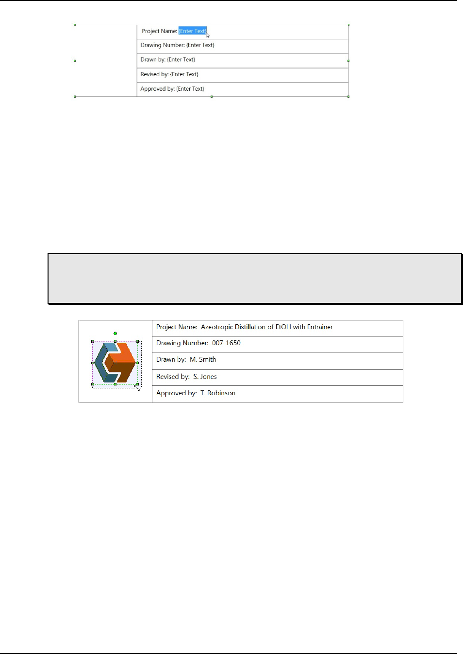
Output and Reports
118 CHEMCAD User Guide
Figure 8-20: Selecting a portion of the text to edit
Adding an Image to a Title Block
To insert a logo or other image in your title block, click the Drawing tab, then click
Image in the Insert group. This brings up an Open dialog, where you can navigate to
the directory where your image file is stored. When you locate the file, double-click
it, or select it and then click Open.
This returns you to the workspace, with the newly imported image highlighted.
You can now drag the image onto an open area on the title block, and use the green
sizing handles on any corner to resize the image as needed.
Note: Be careful to use only the corner handles when resizing an image. Using the
handles along the sides of the box will distort the image, whereas using the corners
will preserve the image’s original shape as you scale it to a larger or smaller size.
Figure 8-21: Resizing an imported image
You can group the image and the title block together so that they will behave as a
single unit. To do this, first click the image, then hold down [
SHIFT] as you click
anywhere on the title block. Then with both items selected, click the Arrange drop-
down on the Drawing toolbar and select Group.
Now when you drag the title block to a different location, the image will move
along with it. If you ever want to remove or replace the image, you can select the title
block and then use the same method with the Ungroup command. Once the items
are ungrouped, you can select the image independently from the title block and
delete it.
Creating a Custom Title Block
After you have customized the content of a title block with your own field labels and
image, you may want to save time by making this title block available for other
flowsheets. To do this, use the Title Block Designer tool.

Output and Reports
CHEMCAD User Guide 119
If you already have a custom title block, start by selecting it on the flowsheet.
Right-click and select Copy from the pop-up menu. Then go to the Tools tab and
click Title Block Designer in the Flowsheet group.
In the Select Title Block dialog, choose the .tbd file that you used to start your
customized title block, or any of the other .tbd options, and click Open. This brings
up a new tab on the CHEMCAD workspace, called Title Block 1. The title block you
chose is displayed in its own workspace tab. At the top of the screen, a special Title
Block Designer tab now displays, offering drawing objects and other items specific
to customizing a title block.
If you were starting a new customized title block, you could begin changing the
text and adding an image, as discussed before. But if you have copied in a title block
with your custom content, you can simply right-click in the workspace and select
Paste. This places your customized title block on the tab; you can now select and
delete the title block with the placeholder text.
You will probably want to delete some of the specific text that you copied in with
the title block, such as a date, title, or drawing number. You could choose to add
your own placeholder text, for example to suggest a standard date format, or you
may simply leave a character such as X to provide a place for users to begin typing.
To make your title block available for future use, you must save it as a .tbd file.
In the Title Block Designer tab’s Workspace group, click Save As, and then provide
a unique name. When you click Save, the workspace tab will display your new title
block name.
Close the tab to return to the main CHEMCAD workspace and the open
simulation. To test your new custom title block, click the Drawing tab, then in the
Insert group, click Title Block. Choose your new .tbd file and click Open. The
custom title block will appear on the workspace.
Using the Layers Feature for Selective Viewing and Printing
A layer is a group of objects in a simulation file—any combination of databoxes,
drawn shapes, text labels, streams, and UnitOps—that you can view or hide with a
single click. You can create one or more layers, define which objects belong to each
layer, and then toggle any layer either on (visible) or off (hidden). The commands for
layers are available both on the command ribbon and in the Explorer pane’s
Simulation tab.
Note: Turning off a layer only hides its assigned flowsheet objects from view. Having
a layer hidden does not in any way affect the way the simulation runs, nor does it
change any stream or UnitOp properties.

Output and Reports
120 CHEMCAD User Guide
Finding the Layer Commands
On the ribbon, the Layers command is located on the View tab, in the Flowsheet
group. When you click this command, a drop-down menu displays the layer
commands that are currently available. Before you have created any layers, the only
available command is New Layer.
Figure 8-22: Clicking the Layers drop-down on the View tab
The Explorer pane also includes a top-level item called Layers, which lists any
layers that you have created in the current simulation. On this list, you can see at a
glance which layers are currently visible ( ) and which are hidden ( ).
Figure 8-23: The Layers entry on the Explorer pane, listing visible and hidden layers
Creating a New Layer
Before you can assign objects to a layer, you must first create a new layer to use. You
can do this in either of two ways:
• On the View tab, click Layers and then select New Layer.
• On the Explorer pane, right-click the Layers item and select New.
In the New Layer dialog, type a descriptive name for the new layer and then
click OK.
The new layer name now displays both on the Explorer pane and in the Layers
drop-down menu. New layers are visible by default.
Note: To change the name of a layer you have created, either select it in the Layers
drop-down menu or right-click it in the Explorer pane list, then choose Rename. In
the New Layer dialog, type the new name and click OK.

Output and Reports
CHEMCAD User Guide 121
Assigning Objects to a Layer
As soon as you have a layer, you can assign objects to it. Start by clicking an object to
highlight it; you’ll see the small green boxes that define its outer edges.
With the object selected, you can assign it to a layer using either of two methods:
• On the View tab, click Layers, then select the desired layer from the drop-down
list and click Add Selected.
• In the Explorer pane, right-click the name of the desired layer and choose Add
Selected.
To save time, you can add multiple objects to a layer at once. Just hold down the
[SHIFT] key as you click each object in turn, then use the Add Selected command as
you did for a single object.
Hiding and Viewing Layers
As soon as you have added at least one object to a layer, you can test the layer by
hiding it and watching what happens. You can use either of these methods to hide or
view a layer:
• On the View tab, click Layers, then select the desired layer from the drop-down
list and click Show/Hide.
• In the Explorer pane, simply click the layer name.
Each time you open a simulation file, CHEMCAD displays or hides its layers
according to the way they were set the last time you saved the simulation. The status
of all layers can be seen in the Explorer pane (the eye icon indicates a visible layer,
while the eye with a slash indicates a hidden one), or in the drop-down menu when
you click the Layers command (a check mark on the list indicates a visible layer).
Removing an Object from a Layer
If you no longer want a specific object or group of objects to be assigned to a given
layer, first ensure that the layer in question is visible. Then select the relevant objects
and do either of the following:
• On the View tab, click Layers, then select the desired layer from the drop-down
list and click Remove Selected.
• In the Explorer pane, right-click the name of the desired layer and choose
Remove Selected.
Now when you hide the layer, the object or objects you removed should remain
in view.
If you want to ensure that an object is not assigned to any layer, click to select the
object and then do either of the following:
• On the View tab, click Layers, then select Remove Selected.

Output and Reports
122 CHEMCAD User Guide
• In the Explorer pane, right-click the top-level Layers item and choose Remove
Selected from All.
Deleting a Layer
To remove a layer from the simulation, do either of the following:
• On the View tab, click Layers, then select the desired layer from the drop-down
list and click Delete.
• In the Explorer pane, right-click the name of the desired layer and choose Delete.
When you delete a layer, it disappears from the Explorer pane and the drop-
down layer list. If the deleted layer had been hidden, the objects assigned to it now
reappear.
Printing a Process Flow Diagram
When you use the Print command on the main CHEMCAD screen, the result is a
verbatim reproduction of your visible workspace.
If you’re zoomed close in to one portion of your flowsheet when you print, you’ll
get a close-up printout that does not include the rest of the flowsheet. If you’ve
hidden all your stream and UnitOp IDs to keep them out of your way while you fix a
problem, those items will not appear on the printout.
For this reason, the first thing you should do when you’re ready to print a
process flow diagram is to decide what needs to be included on the printout. If you
need the entire flowsheet to appear on the printed diagram, click the View tab, then
in the Zoom group, click Zoom to Fit. (You can zoom manually if you prefer.) You
may want to hide or unpin one or more panes as well, to give yourself more
workspace while you prepare to print.
Next, consider whether your process flow diagram should display UnitOp or
stream databoxes, text notes, or other items in addition to the flowsheet itself. If you
have already created the needed items, make sure that they are placed where you
want them. If you have items that you do not want to include in the print-out, you
can add them to a layer and hide that layer from view while you print.
When all the items you want to print are in place, check once more to ensure that
everything falls within the currently displayed CHEMCAD workspace. Then click
the File tab and select Print. This brings up the Print dialog box, which displays a
preview of how the flowsheet will look on paper. You can select printing options
here, or simply click OK to print the process flow diagram.

CHEMCAD User Guide 123
Chapter 9
Customizing CHEMCAD
As you become more familiar with the way that CHEMCAD works and the various
options and tools that are available, you may want to make your own additions—
either for specialized items or for those you use frequently. You can customize
CHEMCAD in several ways that save you time by streamlining and simplifying
your workflow. These include:
• Creating and using stream and UnitOp templates
• Adding custom components to CHEMCAD’s component database
• Defining custom thermophysical rules
• Customizing UnitOp palettes and color schemes
• Making your own UnitOp symbols to add to existing or custom palettes
• Building custom UnitOps
• Creating custom dialog boxes for UnitOp settings
• Customizing costing calculations
This chapter discusses all these types of customization, starting with the simplest
procedures and then moving on to more complex customizations that require some
programming experience.
Flowsheet Templates
One of the most effective ways to save time when creating CHEMCAD simulations
is to make use of stream and UnitOp templates. A template is simply a set of
characteristics, which you assign a name and save for later use. When you set up
stream or UnitOp specifications that you know you’ll need to recreate in the future,

Customizing CHEMCAD
124 CHEMCAD User Guide
you can create a template of that stream or UnitOp. You can then duplicate that item
within the same simulation—or in any other simulation—with just a few mouse
clicks.
Creating a Template
To create a stream template, first create the stream you want to clone and give it all
the characteristics you want to include in the template.
Then find this stream on the Explorer pane’s Simulation tab. Expand the
Flowsheet item, then expand the Streams item, and finally double-click the
applicable stream ID. This brings up an item called Save. Click the word Save to
display the Enter Template Name dialog box, then type a name for your new stream
template and click OK. The new template name is now listed beneath the Save item.
To create a UnitOp template, select the appropriate UnitOp ID in the Explorer
pane, and then follow the same procedure used to create a stream template.
Viewing a Template’s Properties
To see what specifications an existing template includes, look it up in the Explorer
pane.
First expand the Templates item at the bottom of the Explorer pane list. For a
UnitOp template, expand the UnitOps item, then expand the name of the relevant
UnitOp type. For example, if you’re looking up a template that you created for a
type of pump that you frequently use, expand the Pump item in the Explorer pane.
Use the same procedure to look up a stream template, except that these templates
are listed all together, not grouped according to type.
When you find the template you want, simply click the template name to view
its stream or UnitOp specifications.
Applying a Template
To apply a stream template, first expand the main Flowsheet item for the stream to
be affected, either by clicking the triangle icon to its left or by double-clicking the
stream name.
When the stream item is expanded, you’ll see the Save item below it, followed by
the names of all the stream templates that you have created. Click the name of the
template you want to apply, then choose OK to confirm that you want to apply this
stream template.
Use the same procedure to apply a UnitOp template. Select the UnitOp to be
affected and then expand it in the Explorer pane to apply the desired template. Bear
in mind that for a given UnitOp, only templates for the relevant UnitOp type will be
listed.

Customizing CHEMCAD
CHEMCAD User Guide 125
Renaming or Deleting a Template
To rename a template, simply find it under Templates in the Explorer pane, right-
click the template name, and select Rename. Type the new name and click OK. This
changes the template name throughout the Explorer hierarchy.
The procedure for deleting a template is similar to renaming a template. Again,
find the template you want under Templates, right-click its name, and select Delete.
Click OK to confirm that you want to delete this template. When you do this, the
template name disappears from the Explorer, but streams or UnitOps that were
specified using the template are not affected in any way.
Note: Any stream or UnitOp template that you create will be available for use with
all other simulations on the same installation of CHEMCAD, until and unless you
delete the template.
Creating Custom Components
The CHEMCAD component database places detailed information about thousands
of chemicals at your fingertips. If for any reason you find that you need to use a
chemical component that does not match any item currently in the CHEMCAD
database, you can create your own component for use with your simulations.
You can create a single component, define a range of pseudocomponents, or
import a component’s physical properties from an external source. These procedures
have similar aims, but differ significantly from one another.
Adding a Single Component
Creating a pure component in the CHEMCAD component database is a two-part
task. You must first create the component and then regress data into the component.
Creating the Component
To create a new custom component, you can use any of five different estimation
methods:
• Create a hydrocarbon pseudocomponent. This is treated like a pure
component in that certain aspects of how it behaves or reacts are known.
• Use the Joback/Lydersen method. With this method you indicate basic
characteristics, and select molecular groups (known as Joback groups, called
Group Assignments in CHEMCAD) from a list, to indicate how many of each
molecular group are present in the component.
• Use the UNIFAC method. This method is similar to Joback/Lydersen, except
that the group list is more specialized toward organic components.
• Create a combustion solid. This method is used to simulate solid
components for which an elemental analysis and heating value are known,
e.g., coal.

Customizing CHEMCAD
126 CHEMCAD User Guide
• Create an electrolyte component. This method creates a component that you
can subsequently use in an electrolyte simulation.
The procedure for creating a pure component is as follows:
1. Click the Component Database tab, then in the User Components group,
click New. This brings up the New Component dialog box.
Figure 9-01: The New Component dialog box
2. Give the new component a descriptive name; it is strongly recommended that
you make this name unique. All other characteristics here are optional, except
for normal boiling point, which is required for the pseudocomponent
method.
3. Select a Correlation option to indicate which of the above methods you will
use, and click OK to continue.
4. The dialog box that appears next depends on the correlation that you
selected:
• Pseudocomponent brings up the Hydrocarbon Correlation dialog box.
• Group contribution – Joback brings up the Group Assignments dialog box.
• Group contribution – UNIFAC brings up the New Component UNIFAC
Groups dialog box.
• Combustion solid brings up the Combustion Solid dialog box.
• Electrolyte brings up the Electrolyte Data dialog box.
Select the appropriate options for your new component and specify as many
characteristics as you like, as accurately as possible. Click OK to continue.
5. In the Select Destination Database dialog box, you will see no databases listed
if this is your first time to add a component. If this is the case, click New to
bring up the Manage Component Databases dialog box.

Customizing CHEMCAD
CHEMCAD User Guide 127
Figure 9-02: The Manage Component Databases dialog box
6. Normally, you’ll need to click Create, which brings up the Save As dialog
box. Navigate to the location you want for your custom component database,
give the database a name, and click Save. If you want to add a database that
someone else has created (generally in a network location), you can click
Connect, which brings up an Open dialog box; navigate to that database’s
location, highlight the database, and click Open.
7. The Manage Component Databases dialog box now lists the database that
you created or selected. Click OK to continue.
8. In the Select Destination Database dialog box, the new database you have just
named is now listed; highlight it and click OK.
9. The View/Edit Component Data menu now appears. Click any item on the
menu to access a dialog box with options for defining your new component.
After defining as many characteristics as possible, click Exit to close the
menu.
The new component is now available to add to your current simulation and all
future simulations. To return at any time to make changes to a user-defined
component, go to the Component Database tab and do one of the following:
• In the System Database group, click View/Edit Component to bring up the
Select Single Component dialog box, which lists all available components.
Highlight the component you want in the list and click OK to bring up the
View/Edit Component Data menu.
• In the Simulation Database group, click View Components to bring up the
list of components in the current simulation. Double-click the component you
want in the list (or highlight the component and click View/Edit) to bring up
the View/Edit Component Data menu.

Customizing CHEMCAD
128 CHEMCAD User Guide
Regressing Data into the Component
Data regression is the process of fitting experimental data points to a polynomial
equation form, so that the individual error of each data point is minimized.
Data regression is only relevant to temperature-dependent properties such as
heat capacity, density, and vapor pressure. CHEMCAD uses these polynomial
equation fits to calculate the properties of a component at any given temperature.
To regress data into a component that you have created, follow these steps:
1. Click the Component Database tab, then in the User Components group,
click Property Regression. This brings up the Select Regression Data Set
dialog box.
Figure 9-03: The Select Regression Data Set dialog box
2. Select the user-added component that you want to regress and click New.
This brings up the Edit Regression Set dialog box.
Figure 9-04: The Edit Regression Set dialog box

Customizing CHEMCAD
CHEMCAD User Guide 129
3. Select a regression type and provide a descriptive name for the data
regression, then click OK. This brings up a dialog box that displays
parameters for the selected regression type.
4. Verify the data on this dialog box, making additions or changes as necessary,
and then click OK. This brings up a dialog box for data entry.
5. Enter your experiential data points in the cells provided. You can enter a
value in the Weight_factor column to weight the regression toward one or
more data points. When you have entered all of your data points, click OK.
Note: You can paste a contiguous range of cells from an Excel worksheet into the
cells in this dialog box.
6. The regression data is displayed in a tab in the main CHEMCAD window.
Another tab displays the regression results in graphical format. Review the
data and chart, and decide whether the regression adequately represents
your experimental data.
7. A dialog box appears, asking how you would like the changes to be applied
to existing simulations. Choose an option and then click OK.
8. Repeat this procedure as needed to regress other properties for your
component.
Defining a Petroleum Assay Range
Using a petroleum assay—another term for a distillation curve—you can cut a
hydrocarbon stream into pseudocomponents, or fractions. A pseudocomponent
represents a group of components that boil within a narrow temperature range.
Pseudocomponent ranges are used in CHEMCAD to model hydrocarbons.
When you define a petroleum assay for a stream, CHEMCAD creates entries in
the component database for each hydrocarbon cut, and assigns these components’
compositions to the stream.
Note: Before you define a petroleum assay, make sure that you have specified in
your component list, as appropriate, water and any light ends that exist in the assay.
1. Click the Thermophysical tab, then in the Petroleum Assay group, click
Initialize.
2. In the Select Streams dialog box, enter the appropriate stream number(s) and
click OK.
3. In the Hydrocarbon Correlation dialog box, select the appropriate
correlations for your curve, or use the default selections and click OK.
4. This brings up the Curve Temperature Cut Ranges dialog box. For each cut
range that you want to define, provide a beginning and ending temperature,

Customizing CHEMCAD
130 CHEMCAD User Guide
and enter the number of points that you want to define as discrete
pseudocomponents within that range. Click OK to continue.
5. In the Bulk Properties dialog box, specify a petroleum assay type and enter a
total flow rate and bulk gravity for the stream. You can make other entries
here as needed, but only these three items are required. Note that if you have
viscosity data that you want to use, you must check the Viscosity box here.
Click OK to continue.
6. In the resulting dialog box, enter the data from your assay, specifying the
volume percentage and boiling temperature for at least five data points. Click
OK to continue.
7. The next dialog box is optional. Enter a gravity curve from your assay, listing
the volume percentage and specific gravity for at least five data points. Click
OK to continue.
8. The next dialog box is also optional. If you have light ends and water defined
in your assay, enter volume percentage data here for all relevant components.
Click OK to continue.
9. If you checked the Viscosity box on the Bulk Properties dialog, you will now
see the Viscosity Data dialog box. Enter your viscosity data and click OK.
10. The pseudocomponent properties now display in a tab in the main
CHEMCAD window. You can review and print these results, and leave the
tab open as long as you like. To return to the main workspace and your
flowsheet, simply click the far left tab, which displays the name of your
simulation.
11. To see the list of pseudocomponents that you have created, edit the
properties for the stream you selected. The pseudocomponents will be listed
after pure components, with names that begin with NBP.
Importing a Neutral File
You can also add a component to the database by importing its physical properties
from an external data source. This procedure is known as neutral file import.
For detailed information about importing and using a neutral file, see the
CHEMCAD Help system.
Customizing Thermodynamics
Occasionally, you may find that none of the thermodynamic models built into
CHEMCAD serve your needs for a particular simulation. If this should happen, you
can take one of two approaches to handling thermodynamics for the simulation:
either create your own K-value or enthalpy model or create your own mixing rule.

Customizing CHEMCAD
CHEMCAD User Guide 131
Creating a Custom K-value or Enthalpy Model
The K-value for any component is a ratio that reflects the amount of that component
present in vapor and liquid phases under given conditions. CHEMCAD uses K-
values to calculate vapor-liquid equilibrium in streams and in UnitOps.
An enthalpy model calculates the heat content of a system under given
conditions. Enthalpy models are used to calculate the heat balance in CHEMCAD
simulations.
If you have a K-value or enthalpy method that you’d like to use, you can write
C++ code to introduce your model into the CHEMCAD system. A detailed
description of how to create custom K-values and enthalpy models is included in the
User-added Modules Guide, which is available on the Chemstations website.
When you’ve successfully added a custom K-value method, you can select it on
the K-value Models tab of the Thermodynamic Settings dialog box, by using the
Global K-value Option setting called ADDK.
Figure 9-06: Selecting the ADDK K-value option
After adding a custom enthalpy model, you can select it on the Enthalpy Models
tab of the Thermodynamic Settings dialog box, by using the Global Enthalpy Option
setting called ADDH.

Customizing CHEMCAD
132 CHEMCAD User Guide
Figure 9-07: Selecting the ADDH enthalpy model
Creating a Custom Mixing Rule
A mixing rule determines how CHEMCAD calculates the properties of a mixer,
based on the properties of its pure components. You can create custom mixing rules
for any of the selections listed on the Transport Properties tab, either using VBA as
described in the following section or using C++.
Visual Basic Applications (VBA)
You can customize CHEMCAD using Visual Basic Applications, or VBA. The
Explorer pane’s Visual Basic tab provides access to the following types of
customizable items:
• Reactions
• Properties
• UnitOps
If you have written code in VBA that you would like to make available in
CHEMCAD, you can insert that code into one of the templates that CHEMCAD
provides, or use any of these templates as a starting point and launch a VBA editor
from within CHEMCAD.
Defining a Reaction, Mixing Rule, or UnitOp
To define a custom reaction, mixing rule, or UnitOp using VBA, follow these steps:
1. Click the Visual Basic tab in the Explorer pane and expand the relevant item:
Reactions, Properties, or UnitOps.
2. Double-click the relevant template item to open the VBA editor.

Customizing CHEMCAD
CHEMCAD User Guide 133
3. Copy the existing subroutine and paste the code below the example in the
code window. Rename the new subroutine copy.
4. Edit the new subroutine as needed to achieve the result that you want.
5. Return to CHEMCAD by either of two methods:
• Use [
ALT-TAB] or the Windows taskbar, leaving the VBA editor window
open.
• Click the View CHEMCAD button at the far left end of the VBA editor’s
toolbar to close the editor window.
Note: You can also use the [ALT–F11] key combination to toggle between CHEMCAD
and the VBA editor.
6. Save the current CHEMCAD simulation, then expand the relevant Explorer
item again to see your newly defined item in the list.
Using a VBA-defined Reaction
Once you have defined a new reaction, you can use it for a kinetic or batch reactor:
1. Find the Vessel Reactor or Kinetic Reactor symbol on the palette, and drag a
copy onto the flowsheet. Add and specify streams for this UnitOp as
appropriate.
2. Double-click the icon to define reactor specifications. Make the following
selection to use your VBA-defined reaction.
• Vessel reactor: After specifying the reactor’s initial charge, you’ll see the
Vessel Reactor General Information dialog box. On the General tab, select
the kinetic rate expression option called Define each reaction.
• Kinetic reactor: On the General Specifications tab of the Kinetic Reactor
dialog box, select the kinetic rate expression option called Define each
reaction.
3. For each reaction that you define, you’ll enter data into a Kinetic Data dialog
box. Choose the Kinetic Rate Expression option called User - VBA. This
brings up a drop-down list to the right of the Kinetic Rate Expression field,
where you can choose a user-defined reaction. Select the appropriate option
for each reaction that you define for this UnitOp, and then click OK to
continue to the next reaction.

Customizing CHEMCAD
134 CHEMCAD User Guide
Figure 9-08: Selecting a VBA-defined reaction in the Kinetic Data dialog box
4. When you have defined the last reaction, click OK to return to the main
CHEMCAD window.
Using a VBA-defined Mixing Rule
Once you have defined a new mixing rule, you can include it in your CHEMCAD
simulations:
1. On the Home tab, in the Setup group, click Thermodynamic Settings.
2. In the Thermodynamic Settings dialog box, drop down the list of options for
the mixing rule that you used as a template for your new rule. Select your
rule from the list.
3. Click OK to return to the main CHEMCAD window.
Using a VBA-defined UnitOp
Once you have defined a new VBA UnitOp, you can include it in your CHEMCAD
simulations:
1. Find the VBA UnitOp symbol on the palette, and drag a copy onto the
flowsheet. Add streams into and out of the UnitOp as you normally would.
2. Double-click the icon to define the UnitOp’s specifications.
3. In the Visual Basic UnitOp dialog box, drop down the Function list to see the
available VBA UnitOps. Select the one you want to use and click OK.

Customizing CHEMCAD
CHEMCAD User Guide 135
Figure 9-09: Selecting a VBA UnitOp
Customizing UnitOp Palettes
The introductory discussion of the CHEMCAD interface described how to use the
UnitOp palette and make simple changes to its appearance. More advanced palette
customization enables you to do the following:
• Create a custom palette with the UnitOp symbols of your choice
• Copy an existing palette and customize its contents
• Rename a palette
• Use a custom color scheme to change UnitOp symbol colors
• Reset palettes to their default configuration
Creating a Custom Palette
To create a new palette with custom-selected UnitOps, right-click the title bar of any
existing palette and select New. This creates a palette heading called New, and an
empty palette.
To give the palette a distinctive name, you can now right-click the palette
heading and select Rename. Then type the name you want and click OK. Before
proceeding, ensure that the Lock Palette feature is turned off. This will enable you to
copy and paste items from existing palettes.
Now find a symbol that you want to copy into your new palette, and hold down
[CTRL] while you right-click the symbol. Select Copy from the resulting menu, then
open your new palette. With your cursor anywhere in the palette space, hold down
[CTRL] and right-click the mouse. Select Paste from the pop-up menu to place a
copy of the symbol in the new palette.
Copying an Existing Palette
To copy any palette (whether built-in or user-added), first open the palette in
question. Then simply right-click the palette heading and select Copy. Type a name
for the new palette and click OK.

Customizing CHEMCAD
136 CHEMCAD User Guide
Renaming a Palette
To change the name of any palette, first open the palette in question. Then right-click
the palette heading and select Rename. In the Rename Palette box, type the name
you want to use for the palette and click OK. The palette will now display the new
name.
Note: The Rename command is very useful when you have just created a new
custom palette, as the initial name for all new palettes is New.
Using a Custom Color Scheme to Change UnitOp Symbol Colors
In addition to the three built-in color schemes (Grayscale, System Color, Wireframe),
you can create your own custom color schemes, which can be applied to either built-
in or user-created palettes. Using a custom color scheme enables you to assign new
colors to the standard UnitOp symbols.
To do this, first select or create a palette where you want to change some UnitOp
symbol colors. Right-click the palette heading and select Apply Color Scheme >
New Color Scheme. Type a name for your new color scheme and click OK. The new
color scheme name will now appear in the selected palette header.
The default appearance of any new color scheme is identical to the Grayscale
scheme. Now that a custom color scheme is enabled, however, you can begin to
assign new colors to any item on the current palette.
Hold down [
CTRL] while you right-click a UnitOp symbol, then select Edit Color
Scheme. This brings up the Edit Color Scheme dialog, where you can select new
primary and secondary colors for the symbol.
Note: Using two colors gives the symbol a three-dimensional appearance; to create a
flat look, choose the same color for the primary and secondary options.
Figure 9-10: Default Grayscale colors in the Edit Color Scheme dialog
Choose new colors and then click OK. The symbol appears with the colors you
selected on the current palette.

Customizing CHEMCAD
CHEMCAD User Guide 137
Figure 9-11: The standard Equilibrium Reactor symbol with (from left) Grayscale, System Color,
two-tone custom, and single custom coloring
Repeat this process for any other UnitOp symbols for which you want to create
custom colors. The changes you make in a custom color scheme will affect only those
palettes to which you assign the scheme.
You can remove a custom color scheme simply by right-clicking any palette
heading and selecting Delete Color Scheme > [scheme name]. Before you do this, be
sure the scheme you are deleting is not currently in use by any palettes.
Resetting Palettes to Default Configuration
As you experiment with palette customization, remember that you can return all the
built-in UnitOp palettes to their default settings by right-clicking any palette heading
and selecting Reset All Palettes.
Note that when you use this command, any user-added palettes will close, but
you can open them again at any time. To open a palette that is not currently
displayed, right-click any palette heading and select Open, then double-click the
desired .trs format file.
Creating Custom UnitOp Symbols
The Palette pane displays the default symbol for every UnitOp type available in
CHEMCAD. Right-clicking the default symbol for any UnitOp opens a sub-palette
that offers alternative symbols. Some symbols are different only in their appearance,
while others provide a different inlet/outlet configuration from the default symbol.
Some UnitOps have a large number of alternative symbols, while others have only
one or two.
If none of the available symbols meets your needs, you can create a custom
UnitOp symbol for use in CHEMCAD. You determine the symbol’s appearance,
assign it a UnitOp type, and set the number and location of its inlet and outlet ports.
The completed custom symbol becomes part of the sub-palette for its UnitOp type,
and is available for use in all simulations that you create or edit with this installation
of CHEMCAD.
Users who program custom UnitOps can also create their own symbols for use
with those UnitOps. The tool within CHEMCAD that is used to create all custom
symbols is called the UnitOp Designer.
The main steps for adding a custom UnitOp symbol are as follows:
1. Open a UnitOp Designer tab in the CHEMCAD workspace.

Customizing CHEMCAD
138 CHEMCAD User Guide
2. Draw and size the symbol.
3. Save the symbol as a .sid drawing file.
4. Add and specify the desired inlet and outlet ports for the UnitOp.
5. Publish the symbol with a name and UnitOp type.
Once you are comfortable working with the UnitOp Designer tool, you can use
cloning and other helpful shortcuts to add other symbols you may need. These time-
saving techniques are discussed later in this section.
Starting the UnitOp Designer
To begin designing your custom UnitOp symbol, click the Tools tab, then in the
Flowsheet group, click UnitOp Designer. This brings up a separate UnitOp Designer
tab in the CHEMCAD workspace, and displays UnitOp Designer in the title bar
where the simulation name is usually found.
Whenever a UnitOp Designer workspace tab is selected, the command ribbon
displays the UnitOp Designer tools that enable you to create and work with custom
UnitOp symbols. If you have other workspace tabs open, such as a simulation
flowsheet or charts, you can switch to them at any time; when you switch back to the
UnitOp Designer tab, the appropriate tools will display again.
Drawing and Sizing the Symbol
The first step in creating a custom UnitOp is to draw the symbol that will represent it
on the UnitOp palette.
The UnitOp Designer tab offers the following tools for creating your new
symbol:
• The full Objects gallery for drawing shapes, including Line, Arrow Line,
Polygon, Ellipse, Circle, Rectangle, Square, and Rounded Rectangle
• The full Arrange gallery, which includes tools for ordering, grouping, aligning,
and rotating drawn objects
• The Text Box tool, for adding text to your UnitOp symbol
• The Image tool, for importing an image file from your computer or network
Use these tools to create the symbol you want to represent your new UnitOp.
Note that in some cases, the drawing tools remain active until you either right-click
on the workspace or select a different tool. If you create a shape unintentionally and
want to remove it, simply click the shape to highlight it, then right-click and select
Delete.
To ensure that your new symbol is similar in size to other items on the UnitOp
palette, you can “borrow” an existing symbol to get a sense of its scale:
1. Click the simulation tab at the bottom of the workspace.

Customizing CHEMCAD
CHEMCAD User Guide 139
2. Drag a symbol of the desired size from the palette to the workspace.
3. Right-click the symbol on the flowsheet and select Copy.
4. Click back to the UnitOp Designer tab.
5. Right-click any blank area and select Paste.
You can now draw your new symbol to a scale that matches this symbol. Be sure
to delete the borrowed symbol, along with any drawing objects that you do not want
to include, before continuing.
Saving the Symbol Drawing
When you have created your new UnitOp symbol, you will save it as a composite
shape before continuing to the next step.
In the Commands group, click Add Ports. This brings up the Save File Before
Adding Ports dialog box, which prompts you to name the file with a .sid extension.
The default location for storing composite shapes used in custom UnitOps is My
Simulations\Symbols. Name the file and then click Save to continue.
Adding and Locating Ports
Now that you have created a composite shape to represent your new UnitOp, you
need to place and specify the desired number of inlet and outlet ports.
Before you begin, be sure that you know how many inlet and outlet ports the
desired UnitOp type is set up to use. The number of ports you add will need to be
compatible with the UnitOp’s configuration.
To start adding ports, click Add Inlets in the Objects group, then click on the
outside edge of your composite shape where you want to place an inlet. A small blue
dot will appear to mark the port’s location. Continue in this way until you have the
desired number of inlet ports for your UnitOp.
Repeat this process with the Add Outlets command, placing the desired number
of outlets on your UnitOp.
To adjust the position of a port, simply click the port dot to highlight it and then
drag it to its new location.
Note: Placing ports precisely on a symbol outline can be challenging when done with
a mouse. Alternatively, you can use your keyboard’s arrow keys to fine-tune the
position of a selected port.
Specifying Ports
Once the ports are all in the correct locations, you can specify them as desired. There
are two specifications available for UnitOp ports: Index and Link Direction.
The Index setting determines the order in which the ports will be calculated
within the UnitOp. By default, the first inlet port that you add is assigned index 1,

Customizing CHEMCAD
140 CHEMCAD User Guide
the second is assigned index 2, and so forth; outlet ports are also numbered in this
way.
The Link Direction setting is optional. When specified, it determines the
orientation of the stream segment entering or exiting a particular port. Link
orientations are given as cardinal directions. For example, you may want all the inlet
ports on the left side of a column to enter horizontally from the left, or the outlet port
on the bottom of a vessel to exit downward, regardless of where connecting UnitOps
are located.
To change the assigned order of a port or specify its link direction, right-click the
port and select Port Identification.
The Select New Port Index dialog suggests a new Index value, which you can
keep or change. To specify the direction of stream entry or exit from the port, select
the desired direction from the Link Direction drop-down list. When you have
finished specifying the port, click OK to close the dialog box.
Once you have viewed or changed the settings for a particular port and then
closed the dialog box, the port number displays next to the inlet or outlet dot. It is
recommended that you specify (or at least verify) the index setting for each inlet and
outlet port before continuing.
Publishing the UnitOp Symbol
The final step in creating a custom UnitOp symbol is publishing the symbol to the
appropriate UnitOp sub-palette. To begin this step, click Publish UnitOp Symbol.
This brings up the UnitOp Symbol Properties dialog.
At the top of the dialog, type a name for the new UnitOp symbol. You can use a
standard UnitOp name, such as Compressor or Flash, or provide a unique name. To
ensure that the name displays properly in the palette, it’s recommended that you
keep the name brief.
Next, make a selection from the UnitOp Type drop-down list, to determine how
CHEMCAD will categorize your new symbol. In the space below, type a short
description of the UnitOp.
When you have finished specifying the symbol’s properties, click OK. In the
Messages pane, the Notifications tab will display a message: The symbol ‘[name]’ has
been published successfully. You can now go to the Palette pane, right-click the UnitOp
type you assigned, and see your new symbol displayed on the UnitOp sub-palette.
To close the UnitOp Designer tool, click the X on its tab at the bottom of the
CHEMCAD workspace. You will be asked if you want to save changes to your
document; if you have finished working on custom UnitOps for the time being, click
No.

Customizing CHEMCAD
CHEMCAD User Guide 141
Time-saving Strategies for Creating Multiple Custom Symbols
In some situations, you may want to create two or more custom symbols that are
similar. You might need two symbols that look nearly the same, or perhaps you
want to create two identical symbol drawings with different port configurations.
Instead of starting over for each symbol, you can use existing .sid files to save time
and effort.
Use an Existing Drawing as a Starting Point for another UnitOp
If you need two or more custom UnitOps that are similar in appearance, but not
quite the same, you can clone one custom symbol and make the needed changes for
other symbols.
To do this, first open the UnitOp Designer (Tools tab, Flowsheet group, UnitOp
Designer) and create your first custom UnitOp, as described above. When you have
completed the publishing step, close the UnitOp Designer tab, then launch the
UnitOp Designer tool again.
On the UnitOp Designer tab, in the Commands group, select Open UnitOp
Drawing. This should bring up the directory where you stored your .sid file after the
initial drawing step of your custom UnitOp creation. Select the desired .sid file and
click Open.
The drawing file opens in the UnitOp Designer tab. You can now make any
needed changes to the drawing: add or delete items, resize an item, change text, and
so forth.
When you have finished making changes, click Add Ports, then give this
drawing a unique .sid filename and proceed as before. To return to the same starting
place again, simply open the original drawing and repeat the process.
Clone a Custom UnitOp Symbol and Change Port Configuration
If you have just created a custom UnitOp symbol, and want to create an identical
symbol with a different port configuration, you can do this quickly and easily.
As soon as your first symbol is published, simply use the port buttons to place
any additional inlets and outlets, or move the ports to different locations, as
required. Be sure to right-click and select Port Identification for each new port, and
number your inlets and outlets in the order they are to be calculated.
When your port configuration is set, continue by clicking Publish UnitOp
Symbol. After you specify the symbol’s name, type, and description, click OK to
publish the symbol.
To see the two symbols side by side, click back into the main simulation tab.
Right-click the relevant UnitOp type to open the sub-palette, and try placing your
new symbols on the flowsheet. You will see that the port configuration is the only
visible difference between the two symbols.

Customizing CHEMCAD
142 CHEMCAD User Guide
Saving a Published UnitOp for Later Port Reconfiguration
In some cases, you can anticipate the need to re-use a custom UnitOp symbol, with a
different port configuration, at a later date. You can save a published symbol,
complete with its port information, to use as a starting point for future custom
UnitOps:
1. After publishing a custom UnitOp, close the UnitOp Designer tab. When
asked “Save changes to UnitOp DesignerX?” click Yes.
2. Give this .sid file a unique name that you will remember next time—e.g.,
“Vacuum Column Template” or “Atmospheric Column with Ports”—and
click Save.
3. When you need another version of this UnitOp with a different port
configuration, launch CHEMCAD and open the UnitOp Designer tool (Tools
tab, Flowsheet group).
4. In the UnitOp Designer Tools tab, in the Commands group, click Open
UnitOp Drawing. In the Open dialog box, choose the “template” .sid that
you saved before, and click Open. The .sid file will open, displaying its ports
and their configuration.
5. Click Add Ports. Give your new version of this symbol a unique .sid name,
then click Save.
6. Add, move, delete, or reconfigure ports as needed, then publish as before.
7. If you want to keep this new version as a template for future changes, be sure
to save when CHEMCAD prompts you as you close the UnitOp Designer tab.
Cloning from the Flowsheet with Publish to Palette
In some cases, you may want to capture the appearance of a UnitOp icon on your
CHEMCAD workspace and place it in a palette for future use. For example, you may
have flipped a pump icon to place the outlet on the left side, or rotated a vessel icon
90 degrees to give it a horizontal appearance.
Whenever you want a new custom UnitOp that looks different from an existing
one (either built-in or user-created), but has the same port configuration, use the
Publish to Palette command:
1. Make sure the UnitOp icon you want to put on a palette is visible in the main
CHEMCAD workspace. This may require opening a simulation in which you
changed the icon’s appearance, or dragging a built-in or custom UnitOp icon
from a palette onto the workspace.
2. If desired, change the UnitOp’s appearance according to your needs. You can
use the drawing tools to embellish the UnitOp symbol; right-click the UnitOp
and use the Flip, Rotate, Line, or Fill commands; or click and drag to change
the icon’s size or shape.

Customizing CHEMCAD
CHEMCAD User Guide 143
3. Click and drag to select the UnitOp icon and any drawn additions, then right-
click and select Publish to Palette.
4. On the UnitOp Symbol Properties dialog, specify the symbol’s name, type,
and description. When you click OK, the new UnitOp symbol is published to
the specified UnitOp subpalette.
Creating Custom UnitOps
If you need a UnitOp that falls outside the range of options offered by CHEMCAD,
you can create a custom UnitOp. The goal of creating a custom UnitOp is to have a
unit where you can enter your own equations to calculate heat and mass balances.
Over the years, CHEMCAD users have created custom UnitOps for purposes as
diverse as membrane separation units, fuel cells, specialized solids handling units,
and crystallizers for the separation of xylenes.
Four items on the All UnitOps palette are dedicated to user-defined UnitOps.
You can create a custom UnitOp using any of the following:
• Excel UnitOp: Created through a combination of the COM interface and the Data
Map interface
• Calculator: Created using an inline C program
• User-added module: Created using Visual Studio or another C++ compiler
• VBA UnitOp: Created through the VBA Editor, which is part of CHEMCAD
The basic procedures for creating custom Excel UnitOps are covered in Chapter
10, Data Interfaces. Calculator UnitOps are defined by a programming language
called Parser, the syntax for which is documented in the CHEMCAD Calculator/Parser
Module guide, available on the Chemstations website.
C++ user-added modules are developed using Microsoft’s Visual C++
development tool, the same tools that were used in the creation of CHEMCAD’s own
UnitOps. The procedures for creating C++ user-added modules for use with
CHEMCAD are detailed in the User-added Modules Guide, which is also available on
the Chemstations website.
VBA UnitOps are defined by VBA subroutines, and are described later in this
chapter.
The method you choose is an important first step toward creating a UnitOp, but
the choice is almost entirely up to you. Calculator UnitOps can be quick and easy to
set up, but they can’t do everything the other methods can. The Excel/Visual Basic
approach is very powerful and uses the familiar Visual Basic language for
development. A drawback to this method is that calculation can sometimes be slow
due to the use of Microsoft Excel to perform the calculations. The most powerful and
fastest calculating method is the C++ user-added module method, but if you are new
to C++, it may be challenging to use. VBA UnitOps are as powerful as those created
using C++, and are much easier to build.
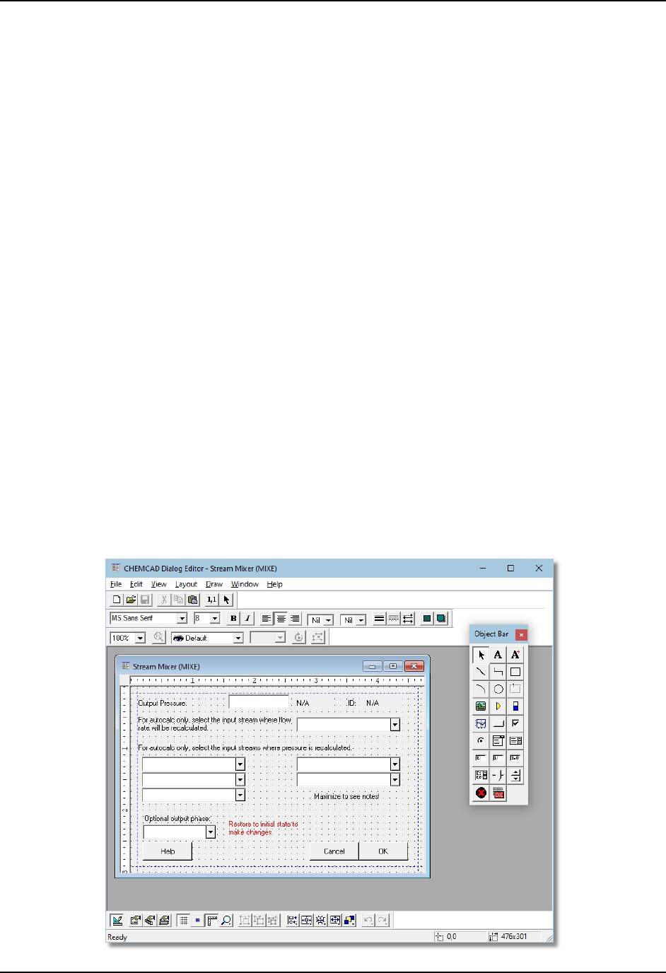
Customizing CHEMCAD
144 CHEMCAD User Guide
Whichever method you use to program the calculations of your UnitOp, you will
likely need to create a dialog box to provide a user interface. A dialog box enables
users to send information into your UnitOp, for example the number of stages for a
distillation UnitOp. No matter what method you use to program your UnitOp, you
will use the Dialog Editor program to create the user interface.
Creating a Custom UnitOp Dialog Box
CHEMCAD uses dialog boxes to set variables for all types of UnitOps. Using the
Dialog Editor program, you can create a custom dialog box for use with any type of
user-added unit.
You can also edit an existing UnitOp’s specification dialog box—for example to
add text notes, to translate from English to another language, or to limit the UnitOp’s
functionality—although this is not commonly done.
The Dialog Editor program enables you to create and modify dialog boxes,
which are controlled by files with the .my extension. These files, along with .map
files and .lab files, define dialog boxes for use in CHEMCAD.
To use the Dialog Editor program, you’ll need a good understanding of
Windows, along with a basic knowledge of Visual Programming concepts such as
objects and properties. You should also have a firm understanding of simulation in
CHEMCAD before venturing into Dialog Editor.
The Dialog Editor program is separate from CHEMCAD. To launch it, open the
full list of available programs from your Windows Start menu and select
Chemstations > Dialog Editor.
Figure 9-12: The Dialog Editor window showing an open dialog

Customizing CHEMCAD
CHEMCAD User Guide 145
A detailed description of how to use the Dialog Editor is available on the
Chemstations website.
Customized Costing Calculations
CHEMCAD includes some very basic costing routines to help determine the capital
cost of equipment. Using a simplified form of C known as the Parser language, you
can modify these routines to better suit your needs. Details of this procedure are
found in the CHEMCAD Calculator/Parser Module guide, available on the
Chemstations website.

Customizing CHEMCAD
146 CHEMCAD User Guide

CHEMCAD User Guide 151
Chapter 10
Data Interfaces
CHEMCAD enables you to exchange data with other programs through a variety of
methods. This saves time, effort, and the potential for keystroke error and data
omissions. In some cases, these data interfaces can enable CHEMCAD to link
directly into your plant information systems to run simulations without human
intervention.
The data interfaces that CHEMCAD uses are as follows:
• The Excel Data Map interface, which can link any value in a CHEMCAD
simulation to any cell in an Excel worksheet, or vice versa (note that running
CHEMCAD simulations from Excel requires a COM interface, described
below)
• The Visual Basic Application interface, which enables you to build custom
reactions, mixing rules, and UnitOps
• The OPC interface, which permits any OPC Client application to access
values in a CHEMCAD simulation
• COM interfaces, which allow any COM-enabled program (such as MATLAB)
to access and control a CHEMCAD simulation
Excel Data Mapping
The Excel Data Mapping feature allows you to link, retrieve, and insert data from an
Excel spreadsheet into a CHEMCAD simulation. It also lets you insert data from a
CHEMCAD simulation into an Excel spreadsheet with just a few clicks. The
integration of CHEMCAD and Excel is a powerful and easy-to-use tool that saves
you time and work.

Data Interfaces
152 CHEMCAD User Guide
With Excel Data Mapping, you can quickly and easily get the most of
CHEMCAD/Excel integration, even if you have no experience with Visual Basic or
Excel programming. In fact, you can use and benefit from this feature even with very
little knowledge of the Excel program.
To use Excel Data Mapping, you must first create one or more Data Maps, and
then set up rules for the execution of each Data Map in use.
Creating an Excel Data Map
The tool used to create and edit Data Maps in CHEMCAD is the Excel Data Map
Editor. This tool displays within the CHEMCAD workspace, and resembles an Excel
spreadsheet. It has all you need to link stream and UnitOp parameters to one or
more Excel spreadsheets. On each Excel Data Map, you can link up to 500
parameters in a single spreadsheet, and you can have up to ten Data Maps per
simulation.
To link your simulation to an Excel spreadsheet, first create the target Excel
workbook, making a note of the file’s name, its location, and the name of the specific
worksheet to which you want to link. Then follow these steps to create a new Data
Map:
1. Click the Tools tab, then in the Data Map group, click New. A spreadsheet
will open within the CHEMCAD workspace.
Figure 10-01: The Excel Data Map Editor
2. Click the Browse button and locate the target workbook. Select the workbook
file and click Open.
3. In the cell next to Excel Worksheet Name, type the name of the worksheet to
which you want to link your simulation.
Note: If you need to verify the name of the worksheet, you can click the Open button
to launch Excel and view the workbook.

Data Interfaces
CHEMCAD User Guide 153
4. Double-click the cell below Map Rule to see a drop-down list of mapping
options:
• To Worksheet Only enables you to send data from streams or UnitOps in
CHEMCAD to the selected worksheet.
• To CC Only enables you to send data from any cell on the worksheet to
the selected stream or UnitOp parameter in your simulation.
• For data reconciliation enables you to manipulate the data using
CHEMCAD’s Data Reconciliation feature.
Figure 10-02: Selecting a Map Rule option in the Excel Data Map Editor
5. Double-click the cell below CC Obj Type to see a drop-down list of mapping
options:
• Stream enables you to link an Excel cell or cell range to a stream on the
flowsheet.
• UnitOp enables you to link an Excel cell or cell range to a UnitOp on the
flowsheet.
• Misc enables you to change dynamic flowsheet settings.
6. Click the cell below CC Obj ID. Type the ID number of the stream or UnitOp
to which you want to link.
7. Double-click the cell below Par ID to see a drop-down list of parameters for
the selected UnitOp or stream. Scroll down and select an option from the list.
Note: When you are importing cell data into CHEMCAD, the list of parameter
options is limited, as many values in a CHEMCAD simulation are calculated based
on other values.
8. If you chose a parameter that is related to a specific component (e.g., Comp
Mole fraction), you will need to specify the component. Double-click the cell
below Component to see a drop-down list of available components. Select a
component from the list.

Data Interfaces
154 CHEMCAD User Guide
9. Click the cell below WrkSht Cell/Range. Type the cell address or cell range
to which you want to link. Cell addresses should be formatted with the
column letter and row number, e.g., A1 or D17. Cell ranges should be
formatted as two such addresses (representing the range’s first and last
values) separated by a colon, e.g., A1:A12 or B5:E20.
10. If you are performing a data reconciliation, you can use the Weight column
to give certain items in the reconciliation more importance than others.
11. Repeat the procedure until you have specified all the cells or cell ranges that
will link to your simulation.
12. When you are ready to save the Data Map, first make sure the Tools tab is
selected. Then in the Data Map group at the left end of the ribbon, click Save
Data Map As. Type a name for your Data Map and then click OK. The newly
created Data Map now appears in the View/Edit drop-down list in the Data
Map group.
Figure 10-03: List of available Data Maps in the simulation
13. To leave the Data Map open and return to your simulation, use the tabs at the
bottom of the main CHEMCAD workspace. To close the Data Map, click the
red X button on its tab at the bottom of the workspace.

Data Interfaces
CHEMCAD User Guide 155
Data Map Execution Rules
After configuring one or more Excel Data Maps for a simulation, you must set up
execution rules to use them. You can configure up to 10 Data Map files per
simulation.
To set up Data Map execution rules, follow these steps:
1. On the Tools tab, in the Data Map group, click Execution Rules. The Data
Map Execution Rule dialog box appears.
Figure 10-04: The dialog box for configuring execution rules
2. Click the square button next to the first field in the Select Data Maps column
to bring up the Select Data Map dialog box.
Figure 10-05: Selecting a Data Map from the list
3. Select the name of the Data Map for which you want to set rules, then click
OK to return to the Data Map Execution Rule dialog box. Repeat this step for
all other Data Maps whose rules you want to set up at this time.

Data Interfaces
156 CHEMCAD User Guide
4. In the Before Simulation Runs field next to each selected Data Map, click the
drop-down list to choose an action for that Data Map to perform before
calculations begin:
• Do Nothing performs no action before the simulation is run. You might
use this option to disable a Data Map temporarily.
• To Workbook sends the requested data to Excel before running the
simulation. You might use this option when you want to pull data from
inlet streams or UnitOp specifications.
• To CHEMCAD sends the requested data in Excel to CHEMCAD before
running the simulation. You might use this option when you want to feed
data to inlet streams or UnitOps with data from the Excel worksheet.
5. In the After Simulation Runs field next to each selected Data Map, click the
drop-down list to choose an action for that Data Map to perform after
calculations are complete:
• Do Nothing performs no action after your simulation has run. You might
use this option to disable a Data Map temporarily.
• To Workbook sends the requested data to Excel after running the
simulation. You might use this option when you want to send data from
streams or calculated parameters of UnitOps to the workbook in Excel.
Figure 10-06: Three different Data Maps with rules set up
6. When you have configured all the Data Maps that you want to use, click OK
to save your rules and close the Data Map Execution Rule dialog box.
You can now run the simulation. If you open the Excel files that are linked to the
simulation, you will be able to see the parameters of streams and UnitOps related to
the Excel Data Map. You can also perform your own calculations in the workbook
based on the data linked to CHEMCAD.

Data Interfaces
CHEMCAD User Guide 157
Creating Excel UnitOps
You can build an Excel spreadsheet that functions as a UnitOp within CHEMCAD.
This is useful for extremely simple UnitOps such as mixers and dividers, or for
simple separations.
1. Start by creating a custom dialog box for your new UnitOp, as described in
Chapter 9, Customizing CHEMCAD.
2. Next, create an Excel workbook containing your desired calculations for the
new UnitOp.
3. Open a simulation and find the Excel UnitOp symbol on the Palette. Drag
this UnitOp symbol onto the workspace.
4. Draw the appropriate streams into and out of the Excel UnitOp.
5. Double-click the Excel UnitOp symbol to open the Excel WorkBook Unit
dialog box.
6. On the File Paths tab, use the top Browse button to specify the location and
file name of the custom dialog box that you created. Use the second Browse
button to specify the location and file name of the Excel workbook that
contains the calculations for this UnitOp.
7. Now you need to specify how this spreadsheet will link to CHEMCAD. Click
the Data Maps tab to link the spreadsheet using one or more Data Maps, or
click the Excel Macros tab to link the spreadsheet using the COM interface.
• On the Data Maps tab, specify the execution rules as described earlier in
this chapter.
• On the Excel Macros tab, specify the names of the Excel macros that you
have programmed to use the COM interface, in the order that you want
them to be calculated.
8. Click OK to return to the main CHEMCAD window.
Specification Sheets
Using the interface with Microsoft Excel, CHEMCAD allows you to output
simulation data to an Excel spreadsheet resembling a vendor specification sheet, as
discussed in Chapter 8, Output and Reports. Customizing these spec sheets saves you
time by outputting data in the format required by your company or vendor.
To customize the spec sheet for a specific UnitOp type, edit the corresponding
Excel spreadsheet in the CHEMCAD templates directory. A typical pathname for
this directory is:
C:\Program Files\Chemstations\CHEMCAD NXT\templates

Data Interfaces
158 CHEMCAD User Guide
If the UnitOp type you want is not represented by the Excel files in this directory,
you can copy the generic specsheet.xls file and use it as a template for a new UnitOp
spreadsheet.
Place the copy in the same directory, and make its file name the standard four-
character abbreviation for the UnitOp type in question. For example, to create a spec
sheet template for the Flash UnitOp, you would need to name the file copy flas.xls.
See the CHEMCAD Help information about your specific UnitOp if you need to look
up this abbreviation.
Before you continue, you will need to turn off the Read-only attribute for the
new spreadsheet file. The quickest way to do this is to right-click the file within the
Windows Explorer, select Properties, and then clear the Read-only check box in the
Properties dialog box.
Once the copy is renamed and the Read-only attribute is turned off, you can
open the spreadsheet and edit it as needed.
Using CHEMCAD as an OPC Server
CHEMCAD is capable of setting up an OPC server which allows direct data transfer
between any CHEMCAD simulation and any OPC client application.
OPC stands for OLE for Process Control. OPC provides a standard method for
different devices and applications to share data. Using OPC, you can share data
between CHEMCAD simulations and SCADA systems, data historians, distributed
control systems (DCS), and human-machine interfaces (HMIs).
In fact, the acronym OPC is now considered by many to mean Openness,
Productivity, Connectivity, because this technology forms the basis for sharing and
manipulating plant data.
OPC-enabled systems are classified as either OPC servers or OPC clients. OPC
servers are either applications or devices that provide data. OPC clients are
interfaces that use and manipulate this data. OPC clients can connect to multiple
OPC servers at any time and read and write data to all of them.
OPC Applications
OPC can be applied as follows:
• Inferential sensors: Sometimes called soft sensors, inferential sensors use one
or more measured variables to estimate another variable. Using CHEMCAD
simulations and data from your plant’s DCS, you can embed simulations to
provide data such as concentrations, heat duty, and fouling factor, which
would not normally be available.
• Operator training: You can couple an operator HMI to a dynamic simulation
to create a training simulator that can help train operators in a safe and
effective way.

Data Interfaces
CHEMCAD User Guide 159
OPC Compliance
Chemstations is a Member of the OPC Foundation, an organization devoted to
maintaining the OPC standards. CHEMCAD has been certified for, and interop
tested for, OPC DA standard 2.05a.
Enabling CHEMCAD as an OPC Server
To enable OPC within CHEMCAD, start by clicking the File tab and then selecting
Preferences. On the left side of the Preferences dialog box, click Connections, then
OPC. Check the Enable OPC Server box and click OK. When you do this,
CHEMCAD registers an OPC server named CHEMCAD.SimulationServer.1 on
your machine.
Once you load a simulation, all of that simulation’s stream properties and
UnitOp settings and variables are automatically published as tags to the OPC
server’s namespace.
Every value tag has a units tag associated with it, which shows the engineering
units used to report the value. To change the engineering units, click Engineering
Units (Home tab, Setup group) within a CHEMCAD simulation.
When the OPC server feature is enabled, CHEMCAD automatically registers
itself as an OPC server. If you want to unregister CHEMCAD and remove it from the
list of OPC servers, you can open a Windows command prompt and type the
following command:
{program directory}\CCNXT.Exe –unregister
For example, if your program directory were C:\Program
Files\Chemstations\CHEMCAD NXT\Program, you would type the following:
C:\Program Files\Chemstations\CHEMCAD NXT\Program\CCNXT.exe -unregister
Reading and Writing Values to CHEMCAD Using OPC
You can use OPC to have values read from or written to a simulation, and to run the
simulation. Both steady-state and dynamic simulations can be run in this way.
Values are updated to the OPC server whenever CHEMCAD completes a steady-
state run or a dynamic time step. Values can also be read; in the case of a dynamic
simulation, reading values between time steps will cause the program to extrapolate
from the last converged results.
Values can be written at any time. If CHEMCAD is in the process of executing a
time step or a steady-state simulation, the values are held in a buffer until the
simulation is converged, at which time the values are written to CHEMCAD.
When values are written to a CHEMCAD stream, the stream is immediately
reflashed, and all OPC tags for that stream are updated.

Data Interfaces
160 CHEMCAD User Guide
OPC Server Operations
In addition to reading and writing process data to CHEMCAD, it is useful to be able
to send commands to CHEMCAD, for example to tell CHEMCAD to start or stop
running a simulation.
This is done with a series of flags in the CHEMCAD group of the OPC server. To
use any of these flags, write a 1 to flag. CHEMCAD will execute the desired
command and return a value indicating success or failure. A return of 0 indicates
that the command has completed successfully, while a negative return indicates a
problem of some kind.
The available commands are as follows:
• Refresh Server tells CHEMCAD to refresh all data sent to the OPC server.
• Run Steady State runs a steady-state simulation. When the simulation
finishes, the flag will be reset either to 0 (run converged) or to a negative
number indicating the number of errors that occurred during the run. To
view the error message text, you must open the CHEMCAD interface
directly.
• Restore to initial state returns a dynamic simulation to time zero. A return of
0 indicates success; a value of -1 indicates failure.
• Run Dynamic starts a dynamic simulation. A return of 0 indicates success; a
value of -1 indicates failure.
• Run Dynamic One Step runs a single time step of a dynamic simulation. A
return of 0 indicates success; a value of -1 indicates failure.
• Set Initial State sets the current process conditions as the time-zero
conditions, overwriting the previous time-zero conditions. A return of 0
indicates success; a value of -1 indicates failure.
• Stop Simulation stops a dynamic simulation. A return of 0 indicates success;
a value of -1 indicates failure.
CHEMCAD OPC Namespace
An OPC namespace defines and organizes all the available commands and data.
OPC namespaces are divided into groups, each of which contains items. Items are
sometimes referred to as tags.
Note: Most of the data items in a simulation have engineering units associated with
them. In these cases, we usually define two separate tags, one containing the data
value and the other containing the units string. All units strings are read only from
OPC. The units strings are governed by the settings inside the simulation.

Data Interfaces
CHEMCAD User Guide 161
The groups in CHEMCAD’s OPC namespace are organized as follows:
• CHEMCAD.SimulationServer: This is the OPC server name. By convention,
this name is followed by a version number, e.g.,
CHEMCAD.SimulationServer.1, to indicate the OPC Server version. This is
the server name to which OPC clients will connect.
• CHEMCAD Group: This group contains any information that is not
dependent on a stream or UnitOp, and all commands used to run
CHEMCAD.
• Streams Group: This group contains a series of subgroups, one for each
stream on the flowsheet numbered by stream ID number.
• UnitOperations Group: This group contains a series of subgroups, one for
each unit operation on the flowsheet, numbered by UnitOp ID number.
COM Interfaces
Component Object Model (COM) is a Microsoft-standard platform that enables
programs to share content such as data and calculation routines. This interface
makes it possible for other programs to control a CHEMCAD simulation.
CHEMCAD acts as a COM server, so any program that can act as a COM client
can be made to interface with CHEMCAD in this way. If you aren’t certain whether
your application can act as a COM client, check with the software vendor.
Note: Using the COM interface to CHEMCAD is a complicated procedure that
requires some experience in programming. If your organization lacks in-house
expertise in programming, consider bringing in a third-party resource to assist you
with the procedure.
The following section is a brief walk-through of a simple COM interface between
Excel and CHEMCAD.
Connecting Excel and CHEMCAD: A Simple COM Interface
While you can export or import data values using Excel Data Map, more
complicated interactions—such as running a simulation from another program—
require the extra control afforded by the COM interface.
The following is a simplified description of the procedure for connecting these
two programs and enabling Excel to load a simulation, change a value, run the
simulation again, read the same value, and then close the simulation.
In this procedure, you’ll use Excel to do the following:
• Open CHEMCAD
• Read in values from CHEMCAD into an Excel workbook
• Change a value in the simulation

Data Interfaces
162 CHEMCAD User Guide
• Run the simulation
• Read the revised values back into Excel
Normally, using COM interfaces involves some programming. We have created
an example called VBCLient.xls to help you overcome that hurdle; you don’t need to
write any code at all to use this tool. Even if you need to write your own program,
the code in the macros of VBClient will come in handy as a guide.
Using the VBClient Example
Follow these steps to use the VBClient example:
1. Open Excel and load the workbook called VBClient.xls. This workbook has
three worksheets:
• Commands contains buttons for controlling a CHEMCAD simulation.
• Streams displays all stream data in the simulation. This sheet can be used
for both input and output of stream variables to the CHEMCAD
simulation.
• UnitOps displays all UnitOp-related data for the simulation. This sheet
can be used for both input and output of UnitOp variables to the
CHEMCAD simulation.
2. On the Commands sheet, you will see a series of buttons used to load
CHEMCAD, load a simulation, read data from the simulation, write data
back to the simulation, and run the simulation. Click Load CHEMCAD to
load CHEMCAD into memory. When a number appears next to CHEMCAD
Version, the program is loaded.
3. Click Load Simulation to browse for and load a simulation into CHEMCAD.
When a file path and name appear next to Simulation, the simulation is
loaded.
4. Now make a change to the data shown on the Streams and UnitOps sheets.
Note: Some values are read-only. For example, VBClient does not allow you
to change a stream’s total flow rate directly; you must instead change the
component flow rates to make a change to the total flow rate.
5. Click Send Changes to push your changes to the CHEMCAD simulation.
6. Click Run All to run the simulation.
7. Note the changes to the data on the Streams and UnitOps sheets.
A Peek under the Hood
Right-click Load CHEMCAD, select Assign Macro, and then click Edit. The Visual
Basic editor in Excel opens to display the code behind the button:

Data Interfaces
CHEMCAD User Guide 163
Sub LoadCHEMCAD()
' initialize global variables
strJobName = ""
selUpdateStrUopData = True
selOK = False
Set objCHEMCAD = Nothing
' load CHEMCAD
Set objCHEMCAD = CreateObject("CHEMCAD.VBServer")
If objCHEMCAD Is Nothing Then
Dim msg As String
msg = "Can not load CHEMCAD"
MsgBox msg
End If
Call UpdateVersion
End Sub
The most important line in that whole subroutine is:
Set objCHEMCAD = CreateObject("CHEMCAD.VBServer")
In that single line, Excel loads CHEMCAD into memory.
Loading a simulation is accomplished with this simple line from the subroutine
called LoadJob:
retval = objCHEMCAD.LoadSim(strJobName, 0)
Running a simulation can be as simple as this line from the RunJob subroutine:
retflag = objCHEMCAD.RunJob
The COM Interface Reference section of the CHEMCAD Help file (listed under
the heading Customization) provides a full reference of the commands available
through COM.

Data Interfaces
164 CHEMCAD User Guide
