
Concise Eurocode 2
for Bridges
A cement and concrete industry publication
For the design of concrete bridges to BS EN 1992-1-1 and BS EN 1992-2
and their National Annexes
O Brooker
BEng CEng MICE MIStructE
P A Jackson BSc(Hons) PhD CEng FICE FIStructE
S W Salim BEng(Hons) PhD CEng MICE

Foreword
The introduction of European standards to UK construction is a significant event as for the
first time all design and construction codes within the EU will be harmonised. The ten
design standards, known as the Eurocodes, will affect all design and construction activities as
current British Standards for structural design are due to be withdrawn in March 2010.
The cement and concrete industry recognised the need to enable UK design professionals
to use Eurocode 2, Design of concrete structures, quickly efficiently and with confidence.
Supported by government, consultants and relevant industry bodies, the Concrete Industry
Eurocode 2 Group (CIEG) was formed in 1999 and this group has provided the guidance for a
coordinated and collaborative approach to the introduction of Eurocode 2.
As a result, a range of resources is being developed and made available through The Concrete
Centre (see www.eurocode2.info). One of those resources, Concise Eurocode 2, published in
2006, is targeted at structural engineers designing concrete framed buildings. Whilst there are
many similarities in the design of buildings and bridges, there are also significant differences
and hence Eurocode 2 has a distinct part for the design of bridges. This publication is based
on the style of Concise Eurocode 2, but has been completely revised and rewritten to suit the
requirements of Eurocode 2, Part 2 and the current design practices for concrete bridge design.
Relevant extracts have been incorporated from Precast Eurocode 2: Design manual published
by British Precast, which is a similar document for designers of precast concrete. The authors
are grateful for the permission granted by British Precast.
Acknowledgements
The Concrete Centre would to thank Neil Loudon and Hideo Takano, both of the Highways
Agency, for their support and comments in producing this document. We would also like to
thank Steve Denton of Parsons Brinckerhoff, Chris Hendy of Atkins and Paul White of Halcrow
for their helpful comments. Thanks are also due to Gillian Bond, Sally Huish and the design
team at Michael Burbridge Ltd for their work on the production.
The copyright of British Standards extracts reproduced in this document is held by the British
Standards Institution (BSI). Extracts have been reproduced with BSI’s permission under the
terms of Licence No: 2009RM0003. No other use of this material is permitted. This publication
is not intended to be a replacement for the standard and may not reflect the most up-to-date
status of the standard. British Standards can be obtained in PDF or hard copy formats from
the BSI online shop: www.bsigroup.com/Shop or by contacting BSI Customer Services for hard
copies only: Tel:+44 (0)20 8996 9001, Email: [email protected].
Published by The Concrete Centre, part of the Mineral Products Association
Riverside House, 4 Meadows Business Park, Station Approach, Blackwater, Camberley, Surrey GU17 9AB
Tel: +44 (0)1276 606800 Fax: +44 (0)1276 606801 www.concretecentre.com
Cement and Concrete Industry Publications (CCIP) are produced through an industry initiative
to publish technical guidance in support of concrete design and construction.
CCIP publications are available from the Concrete Bookshop at www.concretebookshop.com
Tel: +44 (0)7004 607777
CCIP-038
Published July 2009
ISBN 978-1-904818-82-3
Price Group P
© MPA – The Concrete Centre
All advice or information from MPA - The Concrete Centre is intended only for use in the UK by those who will evaluate
the significance and limitations of its contents and take responsibility for its use and application. No liability (including that
for negligence) for any loss resulting from such advice or information is accepted by Mineral Products Association or its
subcontractors, suppliers or advisors. Readers should note that the publications from MPA - The Concrete Centre are subject to
revision from time to time and should therefore ensure that they are in possession of the latest version.
Printed by Michael Burbridge Ltd, Maidenhead, UK.

i
Symbols iv
1 Introduction 1
1.1 Scope 2
2 Basis of design 3
2.1 General 3
2.2 Basicrequirements 3
2.3 Limitstatedesign 4
2.4 Assumptions 9
2.5 Foundationdesign 10
3 Materials 11
3.1 Concrete 11
3.2 Steelreinforcement 13
3.3 Prestressingsteel 14
4 Durability and cover 17
4.1 General 17
4.2 Coverforbond,c
min,b
18
4.3 Coverfordurability,c
min,dur
18
4.4 Chemicalattack 22
4.5
Dc
dev
andotherallowances 23
5 Structural analysis 25
5.1 General 25
5.2 Idealisationofthestructure 25
5.3 Methodsofanalysis 27
5.4 Loading 29
5.5 Geometricalimperfections 29
5.6 Designmomentsincolumns 31
5.7 Corbels 36
5.8 Lateralinstabilityofslenderbeams 38
6 Bending and axial force 39
6.1 Assumptions 39
7 Shear 41
7.1 General 41
7.2 Resistanceofmembersnotrequiringshearreinforcement 41
7.3 Resistanceofmembersrequiringshearreinforcement 44
Contents
ConciseEurocode2forBridges

ii
8 Punching shear 50
8.1 General 50
8.2 Appliedshearstress 50
8.3 Controlperimeters 54
8.4 Punchingshearresistancewithoutshearreinforcement 55
8.5 Punchingshearresistancewithshearreinforcement 56
8.6 Punchingshearresistanceadjacenttocolumns 56
8.7 Controlperimeterwhereshearreinforcementisnolongerrequired,u
out
56
8.8 Distributionofshearreinforcement 57
8.9 Punchingshearresistanceoffoundationbases 58
9 Torsion 59
9.1 General 59
9.2 Torsionalresistances 59
9.3 Combinedtorsionandshear 61
10 Strut-and-tie models, bearing zones and partially loaded areas 62
10.1 Designwithstrut-and-tiemodels 62
10.2 Partiallyloadedareas 65
10.3 Bearingzonesofbridges 66
11 Prestressed members and structures 67
11.1 General 67
11.2 BrittleFracture 67
11.3 Prestressingforceduringtensioning 69
12 Fatigue 72
12.1 Verificationconditions 72
12.2 Internalforcesandstressesforfatigueverification 72
12.3 Verificationofconcreteundercompressionorshear 73
12.4 Limitingstressrangeforreinforcementundertension 74
13 Serviceability 76
13.1 General 76
13.2 StressLimitation 76
13.3 Calculationofcrackwidths 76
13.4 Controlofcracking 79
13.5 Minimumreinforcementareasofmainbars 80
13.6 Controlofdeflection 83
14 Detailing – general requirements 85
14.1 General 85
14.2 Spacingofbars 85
14.3 Mandrelsizesforbentbars 85
14.4 Anchorageofbars 86
14.5 Ultimatebondstress 88
14.6 AnchorageoftendonsatULS 89
14.7 Anchorageoftendonsattransferofprestress 90
14.8 Laps 90

iii
15 Detailing – particular requirements 94
15.1 General 94
15.2 Beams 94
15.3 One-wayandtwo-wayspanningslabs 98
15.4 Flatslabs 98
15.5 Columns 100
15.6 Walls 101
15.7 Pilecaps 102
15.8 Boredpiles 103
15.9 Requirementsforvoidedslabs 103
15.10 Prestressing 104
15.11 Connections 105
15.12 Bearings 106
16 Design for the execution stages 109
17 Design aids 110
17.1 Designforbending 110
17.2 Designforbeamshear 112
17.3 Designforpunchingshear 114
17.4 Designforaxialloadandbending 115
18 References 122

iv
Symbols and abbreviations used in this publication
Symbol Definition
IxI Absolutevalueofx
1/ Curvatureataparticularsection
Cross-sectionalarea;Accidentalaction
Variablesusedinthedeterminationofl
lim
c
Cross-sectionalareaofconcrete
c,eff
Effectiveareaofconcreteintension
ct
Areaofconcreteinthatpartofthesectionthatiscalculatedtobeintensionjustbefore
theformationofthefirstcrack
d
Designvalueofanaccidentalaction
k
Areaenclosedbythecentrelinesofconnectingwallsincludingtheinnerhollowarea
(torsion)
p
Areaofprestressingtendonortendons
p
'
Areaofprestressingtendonswithin
c,eff
s
Cross-sectionalareaofreinforcement
s,min
Minimumcross-sectionalareaofreinforcement
s,prov
Areaofsteelprovided
s,req
Areaofsteelrequired
s1
Areaofreinforcingsteelinlayer1
s2
Areaofcompressionsteel(inlayer2)
sl
Areaofthetensilereinforcementextendingatleast
bd
+beyondthesectionconsidered
sM
(
sN
) Totalareaofreinforcementrequiredinsymmetrical,rectangularcolumnstoresistmoment
(axialload)usingsimplifiedcalculationmethod
st
Cross-sectionalareaoftransversesteel(atlaps)
sw
Cross-sectionalareaofshearreinforcement
sw
Areaofpunchingshearreinforcementinoneperimeteraroundthecolumn
sw,min
Minimumcross-sectionalareaofshearreinforcement
sw,min
Minimumareaofpunchingshearreinforcementinoneperimeteraroundthecolumn
Distance,allowanceatsupports
Geometricdata
D Deviationforgeometricaldata
Anexponent(inconsideringbiaxialbendingofcolumns)
Projectionofthefootingfromthefaceofthecolumnorwall
b
Halfthecentre-to-centrespacingofbars(perpendiculartotheplaneofthebend)
l
Distancebywhichthelocationwhereabarisnolongerrequiredforbendingmomentis
displacedtoallowfortheforcesfromthetrussmodelforshear.(‘Shift’distanceforcurtailment)
v
Distancebetweenbearingsorfaceofsupportandfaceofload
1
,
1
Dimensionsofthecontrolperimeteraroundanelongatedsupport(punchingshear)
Overallwidthofacross-section,orflangewidthinaT-orL-beam
0
Widthofthebottomflangeofthesection
e
Effectivewidthofaflatslab(adjacenttoperimetercolumn)
eff
Effectivewidthofaflange
eq
(
eq
) Equivalentwidth(height)ofcolumn=()forrectangularsections
min
MinimumwidthofwebonT-,I-orL-beams
t
Meanwidthofthetensionzone.ForaT-beamwiththeflangeincompression,onlythe
widthofthewebistakenintoaccount

v
Symbol Definition
w
WidthofthewebonT-,I-orL-beams.Minimumwidthbetweentensionandcompression
chords
y
,
z
Dimensionsofthecontrolperimeter(punchingshear)
D Permitteddeviationfrom
nom
(BSEN13760)
D
,dev
Allowancemadeindesignfordeviation
min
Minimumcover(duetotherequirementsforbond,
min,b
ordurability
min,dur
)
nom
Nominalcover(minimumcoverplusallowancefordeviations)
y
,
x
Columndimensionsinplan
1
,
2
Dimensionsofarectangularcolumn.Foredgecolumns,
1
ismeasuredperpendicularto
thefreeedge(punchingshear)
Diameterofacircularcolumn;Diameterofmandrel;Diameter
Ed
Fatiguedamagefactor
Effectivedepthtotensionsteel
2
Effectivedepthtocompressionsteel
c
Effectivedepthofconcreteincompression
eff
Effectivedepthoftheslabtakenastheaverageoftheeffectivedepthsintwoorthogonal
directions(punchingshear)
g
Largestmaximumaggregatesize
Ashortlengthofaperimeter(punchingshear)
Effectofaction;Elasticmodulus
c
,
c(t)
Tangentmodulusofelasticityofnormalweightconcreteatastressofs
c
=0andattime,
,days
c,eff
Effectivemodulusofelasticityofconcrete
cd
Designvalueofmodulusofelasticityofconcrete
cm
Secantmodulusofelasticityofconcrete
d
Designvalueoftheeffectofactions
Bendingstiffness
p
Designvalueofelasticityofprestressingsteel
s
Designvalueofmodulusofelasticityofreinforcingsteel
Exp. Expression
EQU Staticequilibrium
Eccentricity
2
Deflection(usedinassessing
2
inslendercolumns)
i
Eccentricityduetoimperfections
par
Eccentricityparalleltotheslabedgeresultingfromamomentaboutanaxisperpendicular
totheslabedge(punchingshear)
y
,
z
Eccentricity,
Ed
/
Ed
alongyandzaxesrespectively(punchingshear)
Action
bt
Tensileforceinthebaratthestartofthebendcausedbyultimateloads
c
(
s
) Forceinconcrete(steel)
cd
Designvalueoftheconcretecompressionforceinthedirectionofthelongitudinal
memberaxis
cr
Absolutevalueofthetensileforcewithintheflangeimmediatelypriortocrackingdueto
thecrackingmomentcalculatedwith
ct,eff
d
Designvalueofanaction
E
Tensileforceinreinforcementtobeanchored
Ed
Compressiveforce,designvalueofsupportreaction
k
Characteristicvalueofanaction
Symbols and abbreviations used in this publication

vi
Symbol Definition
rep
Representativeaction(=c
k
wherec=factortoconvertcharacteristictorepresentative
action)
Rs
Resistingtensileforceinsteel
s
Tensileforceinthebar
td
Designvalueofthetensileforceinlongitudinalreinforcement
D
td
Additionaltensileforceinlongitudinalreinforcementduetothetrussshearmodel
wd
Designshearstrengthofweld,designvalueoftheforceinstirrupsincorbels
Wk
Characteristicvalueofwindforce(AnnexA2,BSEN1990)
Frequency
bd
Ultimatebondstress
c
Compressivestrengthofconcrete
cd
Designvalueofconcretecompressivestrength
cd,fat
Designfatiguestrengthofconcrete
cd,pl
Designcompressivestrengthofplainconcrete
ck
Characteristiccompressivecylinderstrengthofconcreteat28days
ck
(
0
) Characteristicconcretecompressivestrengthattimeofloading
ck,cube
Characteristiccompressivecubestrengthofconcreteat28days
cm
Meanvalueofconcretecylindercompressivestrength
ct,d
Designtensilestrengthofconcrete(a
ct
ct,k
/g
C
)
ct,eff
Meantensilestrengthofconcreteeffectiveatthetimecracksmaybefirstexpectedto
occur.
ct,eff
=
ctm
attheappropriateage
ct,k
Characteristicaxialtensilestrengthofconcrete
ctb
Tensilestrengthpriortocrackinginbiaxialstateofstress
ctm
Meanvalueofaxialtensilestrengthofconcrete
ctx
Appropriatetensilestrengthforevaluationofcrackingbendingmoment
ctk,0.05
5%fractilevalueofaxialtensilestrengthofconcrete
ctk,0.95
95%fractilevalueofaxialtensilestrengthofconcrete
cvd
Concretedesignstrengthinshearandcompression(plainconcrete)
p
Tensilestrengthofprestressingsteel
p0.1
0.1%proof-stressofprestressingsteel
p0.1k
Characteristic0.1%proof-stressofprestressingsteel
p0.2k
Characteristic0.2%proof-stressofprestressingsteel
pk
Characteristictensilestrengthofprestressingsteel
sc
CompressivestressincompressionreinforcementatULS
t
Tensilestrengthofreinforcement
t,k
Characteristictensilestrengthofreinforcement
y
Yieldstrengthofreinforcement
yd
Designyieldstrengthoflongitudinalreinforcement,
sl
yk
Characteristicyieldstrengthofreinforcement
ywd
Designyieldstrengthoftheshearreinforcement
ywd,ef
Effectivedesignstrengthofpunchingshearreinforcement
ywk
Characteristicyieldstrengthofshearreinforcement
k
Characteristicvalueofapermanentaction
k
Characteristicvalueofapermanentactionperunitlengthorarea
i
Horizontalactionappliedatalevel
Overalldepthofacross-section;Height

vii
Symbol Definition
0
Notionalsizeofcross-section
f
Depthoffooting;Thicknessofflange
H
Verticalheightofadroporcolumnheadbelowsoffitofaslab(punchingshear)
s
Depthofslab
Secondmomentofareaofconcretesection
Radiusofgyration
Creepfunction
Ed
/
2
ck
.Ameasureoftherelativecompressivestressinamemberinflexure
Factortoaccountforstructuralsystem(deflection)
Valueofabovewhichcompressionreinforcementisrequired
c
Factorforcrackingandcreepeffects
r
Correctionfactorforcurvaturedependingonaxialload
s
Factorforreinforcementcontribution
h Factorfortakingaccountofcreep
Coefficientorfactor
Unintentionalangulardisplacementforinternaltendons
c
Coefficientallowingforthenatureofthestressdistributionwithinthesectionimmediately
priortocrackingandforthechangeoftheleverarmasaresultofcracking(minimumareas)
t
Factorincrackwidthcalculationswhichdependsonthedurationofloading
Clearheightofcolumnbetweenendrestraints
Heightofthestructureinmetres
(or) Length;Span
0
Effectivelength(ofcolumns)
0
Distancebetweenpointsofzeromoment
0
Designlaplength
bd
Designanchoragelength
b,eq
Equivalentanchoragelength
b,min
Minimumanchoragelength
b,rqd
Basicanchoragelength
eff
Effectivespan
H
Horizontaldistancefromcolumnfacetoedgeofadroporcolumnheadbelowsoffitofa
slab(punchingshear)
n
Cleardistancebetweenthefacesofsupports
s
Floortoceilingheight
x
,
y
Spansofatwo-wayslabinthexandydirections
Bendingmoment.Momentfromfirstorderanalysis
Momentresistanceofasinglyreinforcedsection(abovewhichcompressionreinforcement
isrequired)
0,Eqp
Firstorderbendingmomentinquasi-permanentloadcombination(SLS)
01
,
02
FirstorderendmomentsatULSallowancesforimperfections
0Ed
Equivalentfirstordermomentincludingtheeffectofimperfections(ataboutmidheight)
2
Nominalsecondordermomentinslendercolumns
Ed
Designvalueoftheappliedinternalbendingmoment
Edy
,
Edz
Designmomentintherespectivedirection
freq
Appliedbendingmomentduetofrequentcombination
Rdy
,
Rdz
Momentresistanceintherespectivedirection

viii
Symbol Definition
Rd,max
Maximumtransversemomentresistance
rep
Crackingbendingmoment
Numberofverticalmemberscontributingtoaneffect
Mass;Slabcomponents
Axialforce
NA NationalAnnex
a
,
b
Longitudinalforcescontributingto
i
Ed
Designvalueofaxialforce(tensionorcompression)atULS
NDP NationallyDeterminedParameter(s)aspublishedinacountry’sNationalAnnex
AxialstressatULS
Ultimateaction(load)perunitlength(orarea)
Platecomponents
Numberofbars
b
Numberofbarsinthebundle
Prestressingforce
0
Initialforceattheactiveendofthetendonimmediatelyafterstressing
c
Characteristicconstructionload
fat
Characteristicfatigueload
k
Characteristicvalueofavariableaction
k1
(
ki
) Characteristicvalueofaleadingvariableaction(Characteristicvalueofanaccompanying
variableaction)
Sn,k
Characteristicvalueofsnowload
k
Characteristicvalueofavariableactionperunitlengthorarea
ud
Maximumvalueofcombinationreachedinnon-linearanalysis
Resistance
Verticalbearingresistanceperunitarea(foundations)
d
Designvalueoftheresistancetoanaction
Relativehumidity
Radius;Correctingfactorforprestress
cont
Thedistancefromthecentroidofacolumntothecontrolsectionoutsidethecolumnhead
inf,
sup
Allowanceinserviceabilityandfatiguecalculationsforpossiblevariationsinprestress
m
RatiooffirstorderendmomentsincolumnsatULS
Internalforcesandmoments;Firstmomentofarea
S,N,R Cementtypes
SLS Serviceabilitylimitstate(s)–correspondingtoconditionsbeyondwhichspecifiedservice
requirementsarenolongermet
Spacingofthestirrups;Spacingbetweencracks
r
Radialspacingofperimetersofshearreinforcement
r,max
Maximumfinalcrackspacing
t
Tangentialspacingshearreinforcementalongperimetersofshearreinforcement
Torsionalmoment;Tensileforce
Ed
Designvalueoftheappliedtorsionalmoment
k
Characteristicvalueofthermalactions
Rd
Designtorsionalresistancemoment
Rd,max
Maximumdesigntorsionalresistancemomentresistance
Thickness;Timebeingconsidered;Breadthofsupport;Timeaftertensioning

ix
Symbol Definition
0
Theageofconcreteatthetimeofloading
0,T
Temperatureadjustedageofconcreteatloadingindays
ef,i
Effectivewallthickness(torsion)
inf
Thicknessofthebottomflangeofthesection
ULS Ultimatelimitstate(s)–associatedwithcollapseorotherformsofstructuralfailure
Perimeterofconcretecross-section,havingarea
c
Perimeterofthatpartwhichisexposedtodrying
Circumferenceofouteredgeofeffectivecross-section(torsion)
Componentofthedisplacementofapoint
0
Perimeteradjacenttocolumns(punchingshear)
1
Basiccontrolperimeter,(at2fromfaceofload)(punchingshear)
1*
Reducedcontrolperimeteratperimetercolumns(at2fromfaceofload)(punchingshear)
i
Lengthofthecontrolperimeterunderconsideration(punchingshear)
k
Perimeterofthearea
k
(torsion)
out
Perimeteratwhichshearreinforcementisnolongerrequired
Shearforce
Ed
Designvalueoftheappliedshearforce
Ed,red
Appliedshearforcereducedbytheforceduetosoilpressurelessselfweightofbase
(punchingshear,foundations)
Rd,c
Shearresistanceofamemberwithoutshearreinforcement
Rd,max
Shearresistanceofamemberlimitedbythecrushingofcompressionstruts
Rd,s
Shearresistanceofamembergovernedbytheyieldingofshearreinforcement
Transverseshearorcomponentofthedisplacementofapoint
Ed
Punchingshearstress
Ed
Shearstressforsectionsshearreinforcement(=
Ed
/
w
)
Ed,z
Shearstressforsectionsshearreinforcement(=
Ed
/
w
=
Ed
/
w
0.9)
Rd,c
Designshearresistanceofconcretewithoutshearreinforcementexpressedasastress
Rd,cs
Designpunchingshearresistanceofconcreteshearreinforcementexpressedasa
stress(punchingshear)
Rd,max
Resistanceofconcretestrutsexpressedasastress
1
Factorcorrespondingtoadistributionofshear(punchingshear)
Componentofthedisplacementofapoint
k
Crackwidth
max
Limitingcalculatedcrackwidth
Advisorylimitofpercentageofcoupledtendonsatasection
X0,XA,XC, Concreteexposureclasses
XD,XF,XS
Neutralaxisdepth
Distanceofthesectionbeingconsideredfromthecentrelineofthesupport
Co-ordinates;Planesunderconsideration
c
Depthofthecompressionzone
u
Depthoftheneutralaxisattheultimatelimitstateafterredistribution
Leverarmofinternalforces
cp
Distancebetweencentreofgravityofconcretesectionandtendons
s
Leverarmforprestress
a Angle;Angleofshearlinkstothelongitudinalaxis;Ratio
a Longtermeffectscoefficient

x
Symbol Definition
a Ratiobetweenprincipalstresses
a Deformationparameter
a
1
,a
2
,a
3
Factorsdealingwithanchorageandlapsofbars
a
4
,a
5
,a
6
a
1
,a
2
,a
3
Factorsusedincreepcalculations
a
cc
(a
ct
) Acoefficienttakingintoaccountlongtermeffectsofcompressive(tensile)loadandthe
wayloadisapplied
a
cw
Coefficienttakingaccountofthestateofstressinthecompressionchord
a
e
Effectivemodularratio
a
h
Reductionfactorfory
b Angle;Ratio;Coefficient
b Factordealingwitheccentricity(punchingshear)
b(
cm
) Factortoallowfortheeffectofconcretestrengthonthenotionalcreepcoefficient
b
H
Coefficentdependingontherelativehumidityandthenotionalmembersize
b(
0
) Factortoallowfortheeffectofconcreteageatloadingonthenotionalcreepcoefficient
b(,
0
) Coefficienttodescribethedevelopmentofcreepwithtimeafterloading
g Partialfactor
g
A
Partialfactorforaccidentalactions,
g
C
Partialfactorforconcrete
g
C,fat
Partialfactorforfatigueofconcrete
g
F
Partialfactorforactions,
g
F,fat
Partialfactorforfatigueactions
g
f
Partialfactorforactionswithouttakingaccountofmodeluncertainties
g
g
Partialfactorforpermanentactionswithouttakingaccountofmodeluncertainties
g
G
Partialfactorforpermanentactions,
g
M
Partialfactorforamaterialproperty,takingaccountofuncertaintiesinthematerial
propertyitself,ingeometricdeviationandinthedesignmodelused
g
P
Partialfactorforactionsassociatedwithprestressing,
g
Q
Partialfactorforvariableactions,
g
S
Partialfactorforreinforcingsteelorprestressingsteel
g
S,fat
Partialfactorforreinforcingorprestressingsteelunderfatigueloading
g
SH
Partialfactorforshrinkage
d Ratiooftheredistributedmomenttotheelasticbendingmoment.
e
c
Compressivestraininconcrete
e
c1
Compressivestrainintheconcreteatthepeakstress
c
e
c2
Compressivestrainlimitinconcreteforconcreteinpureaxialcompressionorstrainin
concreteatreachingmaximumstrengthassuminguseoftheparabolic-rectangular
relationship
e
c3
Compressivestrainlimitinconcreteforconcreteinpureaxialcompressionorstrainin
concreteatreachingmaximumstrengthassuminguseofthebilinearstress-strain
relationship
e
ca
Autogenousshrinkagestrain
e
cc
Creepstrain
e
cd
Dryingshrinkagestrain
e
cm
Meanstraininconcretebetweencracks
e
cs
Totalshrinkagestrain
e
cu
Ultimatecompressivestrainintheconcrete
e
cu2
Ultimatecompressivestrainlimitinconcretewhichisnotfullyinpureaxialcompression
assuminguseoftheparabolic-rectangularstress-strainrelationship(numericallye
cu2
=e
cu3
)

xi
Symbol Definition
e
cu3
Ultimatecompressivestrainlimitinconcretewhichisnotfullyinpureaxialcompression
assuminguseofthebilinearstress-strainrelationship
e
p(0)
Initialstraininprestressingsteel
De
p
Changeinstraininprestressingsteel
e
s
Straininreinforcingsteel
e
sm
Meanstraininreinforcement
e
u
Strainofreinforcementorprestressingsteelatmaximumload
e
ud
Designlimitforstrainforreinforcingsteelintension=
0.9e
uk
e
uk
Characteristicstrainofreinforcement(orprestressingsteel)atmaximumload
e
y
Reinforcementyieldstrain
n Factordefiningeffectivestrength(=1for≤C50/60)
n
1
Coefficientforbondconditions
n
2
Coefficientforbardiameter
n
p1
Coefficientthattakesintoaccountthetypeoftendonandthebondsituationatrelease
y
Angle;Angleofcompressionstruts(shear)
y
fat
Inclinationofcompressivestruts
y
i
Inclinationusedtorepresentimperfections
l Slendernessratio
l Damageequivalentfactorsinfatigue
l Factordefiningtheheightofthecompressionzone(=0.8for≤C50/60)
l
lim
Limitingslendernessratio(ofcolumns)
m Coefficientoffrictionbetweenthetendonsandtheirducts
m Characteristicvalueofthetensilestrengthofprestressingsteel
v Poisson'sratio
v
1
Strengthreductionfactorforconcretecrackedinshear
j Creepredistributionfunction
j Bondstrengthratio
j
1
Adjustedareaofbondstrength
r Requiredtensionreinforcementratio.Assume
s
/
r Ovendrydensityofconcreteinkg/m
3
r' Reinforcementratioforrequiredcompressionreinforcement,
s2
/
r
0
Referencereinforcementratio
ck
0.5
x10
–3
r
1
Percentageofreinforcementlappedwithin0.65
0
fromthecentrelineofthelapbeing
considered
r
1000
Valueofrelaxationloss(in%)at1000hoursaftertensioningandatameantemperatureof20°C
r
l
Reinforcementratioforlongitudinalreinforcement
r
w
Reinforcementratioforshearreinforcement
s
c
Compressivestressintheconcrete
s
cp
Compressivestressintheconcretefromaxialloadorprestressing
s
cu
Compressivestressintheconcreteattheultimatecompressivestraine
cu
s
gd
Designvalueofthegroundpressure
s
pi
Theabsolutevalueofinitialprestress
s
pm0
Theabsolutevalueofinitialprestressduringpost-tensioning
s
Rd,max
Designstrengthofconcretestrut
s
s
StressinreinforcementatSLS
s
s
Absolutevalueofthemaximumstresspermittedinthereinforcementimmediatelyafter
theformationofthecrack

xii
Symbol Definition
s
sc
(s
st
) Stressincompression(andtension)reinforcement
s
sd
Designstressinthebarattheultimatelimitstate
s
sr
Stressinthetensionreinforcementcalculatedonthebasisofacrackedsectionunderthe
loadingconditionscausingfirstcracking
t Torsionalshearstress
F DynamicfactoraccordingtoBSEN1991-2
h
0
Notionalcreepcoefficient
h(∞,
0
) Finalvalueofcreepcoefficient
h
ef
Effectivecreepfactor
h
fat
Damageequivalentimpactfactorinfatigue
h
nl
(∞,
0
) Non-linearnotionalcreepcoefficient
h
p
Equivalentdiameteroftendon
h(,
0
) Creepcoefficient,definingcreepbetweentimesand
0
,relatedtoelasticdeformationat28days
h
RH
Factortoallowfortheeffectofrelativehumidityonthenotionalcreepcoefficient
f Bardiameter;Diameterofprestressingduct
f
eq
Equivalentbardiameter
f
m
Mandreldiameter
f
n
Equivalentdiameterofabundleofreinforcingbars
X Ageingcoefficient
c Factorsdefiningrepresentativevaluesofvariableactions
c
0
Combinationvalueofavariableaction(e.g.usedwhenconsideringULS)
c
1
Frequentvalueofavariableaction(e.g.usedwhenconsideringwhethersectionwillhave
crackedornot)
c
2
Quasi-permanentvalueofavariableaction(e.g.usedwhenconsideringdeformation)
w Mechanicalreinforcementratio=
s
yd
/
c
cd
≤1

1
Introduction
1
Introduction
BSEN1992-1-1(Eurocode2:Part1-1
[
1
]
)setsoutgeneralrules
for the design of concrete structures and rules for the design of buildings. BS EN 1992-2
(Eurocode 2 -Part 2Concrete bridges- Designand detailing rules)
[
2
]
providesadditional or
amendedguidancetoPart1-1forbridgestructures.
TheaimofthisistodistilfromallrelevantpartsofBSEN1992and
theUKNationalAnnexes materialthatwillbecommonlyusedinthedesignofnormalbridge
structures. Eachcountry can publish non-contradictory,complementary information, and for
concretebridgedesign,PD6687,Part2
[
3
]
givesusefulguidance.Materialfromthisdocumentis
alsoincludedwhereappropriate,andpresentedonapaleyellowbackgroundtodistinguishit
fromthemaintext.
As far as possible, the Eurocode clauses are repeated verbatim.One ofthe objectives is to
embed the UK NationalAnnex values into the document for ease of use. Due to the way
Nationally Determined Parameters (NDPs) are introduced in the Eurocodes it has been
necessaryinsomeplacestomodifythetextforclarityofreading.Ithasnotbeentheintention
tomodifythemeaningofthetextandclearlyifthereisanydoubtastothemeaningthenthe
originalEurocodeversionshouldbeadopted.
Further,someoftheoriginaltexthasbeenmodifiedtoreduceitslength,whilekeepingthesame
meaning.Inthiscasethetexthasbeengivenagreybackgroundtodrawthereader’sattention
tothefactthatthetextisnotstrictlyfromtheCode.Likewiseothertext,derivedformulae,
tablesandillustrationsthatareprovidedtoassistthedesignersbutthatarenottakendirectly
fromtheoriginalhavebeengivenagreybackground.Asbefore,itisintendedtoconveythe
originalmeaningandwhereanydoubtexiststhemeaningofEurocode2shouldbeadopted.
TheNDPs arerecognitionthat each Member Stateof theEU isresponsible fordetermining
matters such as safety and current practice andallow individualcountries to set their own
values.Asnotedabove,theUKvalueshavebeenadoptedthroughout,buthavebeenhighlighted
withagreenbackgroundsothatitiscleartothereaderwhatNDPvaluehasbeenused.
Guide to presentation
Greyshadedtext,
tablesandfigures
ModifiedEurocode2textandadditionaltext,derivedformulae,
tablesandillustrationsnot fromEurocode2
Yellowshadedtext,
tablesandfigures
AdditionaltextfromPD6687
[6]
orPD6687-2
[3]
BS EN 1992-1-1
6.4.4
Relevantcodeandclausesorfigurenumbers
BS EN 1992-1-1
NA
FromtherelevantUKNationalAnnex
BS EN 1992-1-1
6.4.4 & NA
FrombothEurocode2-1-1andUKNationalAnnex
Section 5.2
Relevantpartsofthispublication
1.0
NationallyDeterminedParameter.UKvalueshavebeenused
throughout
For ease of reference, this guide is repeated on the inside back cover.

2
Scope
Thispublicationisintendedtocoverthedesignofatypicalbridge;thereareparticulartypesof
bridgessuchassuspensionbridgesandsegmentalbridgesthatshouldnotbedesignedwithout
referencetotheCodeitself.Itshouldalsobenotedthatnoteverymethodpresentedinthe
Codeisgivenhere.Generally,thesimplestandmoreconservativemethodshavebeenincluded
andthereforethereadermayfindtherearebenefitstobegainedbyusingothermethodsand
shouldconsulttheCodeontheseoccasions.
Thispublicationdoesnotcoverthemethodofdesigningconcreteelementsusingmembrane
rules.Membraneelementsmaybeusedforthedesignoftwo-dimensionalconcreteelements
subject to a combination of internal forces evaluated by means of a linear finite element
analysis.ThereadershouldrefertoBSEN1992-2AnnexLLinconjunctionwithAnnexFand
Cl. 6.109 for detailed guidance. For the design or verification of shell elements subject to
bendingalone (i.e.withzeromembrane forces)the approachesgiven byWoodArmer
[4]
and
Denton&Burgoyne
[5]
maygenerallybeused.
1.1

3
Basisofdesign
Basis of design
General
BSEN1992-1-1
[
1
]
andBSEN1992-2
[
2
]
shouldbeusedinconjunctionwithBSEN1990:
[
7
]
,which:
Establishesprinciplesandrequirementsforthesafety,serviceabilityanddurabilityof
structures.
Describesthebasisfortheirdesignandverification.
Givesguidelinesforrelatedaspectsofstructuralreliability.
Basic requirements
General
Astructureshouldbedesignedandexecuted(constructed)insuchawaythatitwill,duringits
intendedlife,withappropriatedegreesofreliabilityandinaneconomicalway:
Sustainallactionsandinfluenceslikelytooccurduringexecutionanduse.
Meetthespecifiedserviceabilityrequirementsforastructureorastructuralmember.
Itshouldbedesignedtohaveadequatestructuralresistance,serviceabilityanddurability.
Astructureshouldbedesignedandexecutedinsuchawaythatitwillnotbedamagedbyevents
suchasexplosion,impactandtheconsequencesofhumanerrors,toanextentdisproportionate
totheoriginalcause.
Avoidance of damage
Potentialdamageshouldbeavoidedorlimitedbyappropriatechoiceofoneormoreofthe
following:
Avoiding,eliminatingorreducingthehazardstowhichthestructurecanbesubjected.
Selectingastructuralformwhichhaslowsensitivitytothehazardsconsidered.
Selectingastructuralformanddesignthatcansurviveadequatelytheaccidentalremoval
ofanindividualstructuralmemberoralimitedpartofthestructureortheoccurrenceof
localiseddamage.
Avoidingasfaraspossiblestructuralsystemsthatcancollapsewithoutwarning.
Tyingthestructuralmemberstogether.
Limit states principles
BSEN1990impliesthatthedesignshouldbeverifiedusinglimitstatesprinciples.
Anindicativevalueof120yearsisgivenintheUKNationalAnnexforthedesignworking
lifeofbridges.ItcangenerallybeassumedthattheguidancegiveninBS8500
[
8
]
foratleast
a100-year'intendedworkinglife'willbeappropriateforan'indicativedesignworkinglife'
of120years.
BS EN 1990
2.1(1), (2) & (4)
BS EN 1990
1.1.1(1)
BS EN 1992-1-1
1.1.1(3)
BS EN 1990
2.1(5)
BS EN 1990
3.1(1)
BS EN 1990
2.3 & NA
2
2.1
2.2
2.2.1
2.2.2
2.2.3

4
Limit state design
Limit states are states beyond which the structure no longer fulfils the relevant
designcriteria:
Ultimatelimitstates(ULS)areassociatedwithcollapseorotherformsofstructural
failure.
Serviceabilitylimitstates(SLS)correspondtoconditionsbeyondwhichspecifiedservice
requirementsarenolongermet.
Limitstatesshouldbeverifiedinallrelevantdesignsituationsselected,takingintoaccount
thecircumstancesunderwhichthestructureisrequiredtofulfilitsfunction.
Design situations
Normally,innon-seismiczones,thefollowingdesignsituationsshouldbeconsidered:
Persistentsituationswhichrefertotheconditionsofnormaluse.
Transientsituationswhichrefertotemporaryconditions,suchasduringexecutionorrepair.
Accidentalsituationswhichrefertoexceptionalconditionsapplicabletothestructureorto
itsexposuree.g.fire,explosion,impactortheconsequencesoflocalisedfailure.
Actions
Actionsrefertoasetofforces(loads)appliedtothestructure(directaction),ortoasetof
imposeddeformationsoraccelerationscaused,forexample,bytemperaturechanges,moisture
variation,unevensettlementorearthquakes(indirectaction).
Permanentactionsrefertoactionsforwhichthevariationinmagnitudewithtimeis
negligible.
Variableactionsareactionsforwhichthevariationinmagnitudewithtimeisnot
negligible.
Accidentalactionsareactionsofshortdurationbutofsignificantmagnitudethatare
unlikelytooccuronagivenstructureduringthedesignworkinglife.
Thecharacteristicvalue,
k
,ofanactionisitsmainrepresentativevalueandshallbespecifiedby:
Ameanvalue
–generallyusedforpermanentactions.
Anuppervalue
withanintendedprobabilityofnotbeingexceeded
orlowervalue
withanintendedprobabilityofbeingachieved–normallyusedforvariableactionswith
knownstatisticaldistributions,suchaswindorsnow.
Anominalvalue
–
usedforsomevariableandaccidentalactions.
ThevaluesofactionsgiveninthevariouspartsofBSEN1991:
[
9
]
are
takenascharacteristicvalues.
Verification
Verification,usingthepartialfactormethod,isdetailedinBSEN1990
[
4
]
.Inthismethoditis
verifiedthat,inallrelevantdesignsituations,norelevantlimitstateisexceededwhendesign
valuesforactionsandresistancesareusedinthedesignmodels.
BS EN 1990
3.1 & 3.4
BS EN 1990
3.2
BS EN 1990
1.5.3.1
BS EN 1990
1.5.3.3
BS EN 1990
1.5.3.4
BS EN 1990
1.5.3.5
BS EN 1990
4.1.2(1)
BS EN 1990
BS EN 1991
2.3
2.3.1
2.3.2
2.3.3

5
BasisofdesignBasisofdesign
Design values of actions
Thedesignvalue,
d
,ofanaction,,canbeexpressedingeneraltermsas
d
=g
F
c
k
where
g
F
=partialfactorfortheactionwhichtakesaccountofthepossibilityofunfavourable
deviationsoftheactionvaluesfromtherepresentativevalues.
c =afactorfortheaction
c canhavethevalue1.0,c
0
orc
1
orc
2
whichisusedtoobtainthecharacteristic,
combination,frequentandquasi-permanentvaluesrespectively.Itadjuststhevalue
oftheactiontoaccountforthejointprobabilityoftheactionsoccurringsimultaneously.
SeeTables2.1to2.3whicharederivedfromBSEN1990anditsNationalAnnex
[
7a
]
.
k
= characteristicvalueofanaction.
Table 2.1
Values of
c factors for road bridges
Action Symbol c
0
c
1
c
2
Traffic loads (see
BS EN 1991-2,
table 4.4)
gr1a
a
TS 0.75 0.75 0
UDL
0.75 0.75 0
Pedestrianandcycle-trackloads
b
0.40 0.40 0
gr1b
a
Singleaxle 0 0.75 0
gr2 Horizontalforces
0 0 0
gr3 Pedestrianloads
0 0.40 0
gr4 Crowdloading
0 0.75 0
gr5
c
VerticalforcesfromSVandSOVVehicles 0 1.0 0
Wind forces
Persistentdesignsituations
0.50 0.20 0
Duringexecution
0.80 – 0
Duringexecution 1.0 – 0
Thermal actions
0.60
d
0.60 0.50
Snow loads
(duringexecution) 0.80 – –
Construction loads
1.0 – 1.0
Key
a Thevaluesof
c
0
,c
1
andc
2
forgr1aandgr1baregivenforroadtrafficcorrespondingtoadjusting
factorsa
Qi
,a
qi
,a
qr
andb
Q
=1
b Thevalueofthepedestrianandcycle-trackload,giveninTable4.4aofEN1991-2,isa'reduced'value
accompanyingthecharacteristicvalueofLM1andshouldnotbefactoredagainby
c
1
.However,when
gr1aiscombinedwithleadingnon-trafficactions,thisvalueshouldbefactoredbyc
0
c InaccordancewithBSEN1991-2Cl.4.5.2,thefrequentvalueofgr5doesnotneedtobeconsidered.
d The
c
0
valueforthermalactionsmayinmostcasesbereducedto0forultimatelimitstatesEQU,STRand
GEO
Table 2.2
Values of
c factors for footbridges
Action Symbol c
0
c
1
c
2
Traffic loads
gr1
0.4 0.4 0
fwk
0 0 0
gr2
0 0 0
Wind forces
Wk
0.3 0.2 0
Thermal actions
k
0.6
a
0.6 0.5
Snow loads
Sn,k
(duringexecution)
0.8 – 0
Construction loads
c
1.0 – 1.0
Key
a The
c
0
valueforthermalactionsmayinmostcasesbereducedto0forultimatelimitstatesEQU,STR
andGEO
BS EN 1990 NA
table NA. A.2.1
BS EN 1990 NA
table NA. A.2.2
2.3.4
BS EN 1990
6.3.1

6
Table 2.3
Values of
c factors for railway bridges
Actions c
0
c
1
c
2
a
Individual
components of
traffic actions
b
LM71 0.80
c
0
SW/0
0.80
c
0
SW/2
0 1.00 0
Unloadedtrain
1.00 – –
HSLM
1.00 1.00 0
Trackingandbraking
Centrifugalforces
Interactionforcesduetodeformationunderverticaltrafficloads
Individualcomponentsoftraffic
actionsindesignsituationswherethe
trafficloadsareconsideredasasingle
(multi-directional)leadingactionand
notasgroupsofloadsshouldusethe
samevaluesofcfactorsasthose
adoptedfortheassociatedvertical
loads
Nosingforces
1.00 0.80 0
Non-publicfootpathsloads
0.80 0.50 0
Realtrains
1.00 1.00 0
Horizontalearthpressureduetotrafficloadsurcharge
0.80
c
0
Aerodynamiceffects
0.80 0.50 0
Main traffic actions
(groups of loads)
gr11(LM71+SW/0) Max.vertical1withmax.longitudinal
0.80 0.80 0
gr12(LM71+SW/0) Max.vertical2withmax.transverse
gr13(Braking/traction) Max.longitudinal
gr14(Centrifugal/nosing) Max.lateral
gr15(Unloadedtrain) Lateralstabilitywith'unloadedtrain'
gr16(SW/2) SW/2withmax.longitudinal
gr17(SW/2) SW/2withmax.transverse
gr21(LM71+SW/0) Max.vertical1withmax.longitudinal
0.80 0.70 0
gr22(LM71+SW/0) Max.vertical2withmax.transverse
gr23(Braking/traction) Max.longitudinal
gr24(Centrifugal/nosing) Max.lateral
gr26(SW/2) SW/2withmax.longitudinal
gr27(SW/2) SW/2withmax.transverse
gr31(LM71+SW/0) Additionalloadcases
0.80 0.60 0
Other operating
actions
Aerodynamiceffects
0.80 0.50 0
Generalmaintenanceloadingfornon-publicfootpaths
0.80 0.50 0
Wind forces
d
0.75 0.50 0
1.00 0 0
Thermal actions
e
0.60 0.60 0.50
Snow loads
(duringexecution) 0.80 – 0
Construction loads
1.00 – 1.00
Key
a Ifdeformationisbeingconsideredforpersistentandtransientdesignsituations,
c
2
shouldbetakenequalto1.00forrailtrafficactions.
Forseismicdesignsituations,seeTableNAA2.5ofBSEN1990NA
b Minimumcoexistantfavourableverticalloadwithindividualcomponentsofrailtrafficactions(e.g.centrifugal,tractionorbraking)is
0.5LM71,etc.
c
0.8
if1trackonlyisloaded
0.7
if2tracksaresimultaneouslyloaded
0.6
if3ormoretracksaresimultaneouslyloaded
d Whenwindforcesactsimultaneouslywithtrafficactions,thewindforce
c
0
Wk
shouldbetakenasnogreaterthan
W
(seeBSEN1991-1-4).SeeA2.2.4(4)ofBSEN1990
e SeeBSEN1991-1-5
BS EN 1990
table A.2.3

7
BasisofdesignBasisofdesign
Combinations of actions
Ultimate limit states
Thefollowingultimatelimitstatesshallbeverifiedasrelevant:
EQU Lossofstaticequilibriumofthestructureoranypartofitconsideredasarigidbody.
STR Internalfailureorexcessivedeformationofthestructureorstructuralmembers.
GEO Failureorexcessivedeformationofthestructurewherethestrengthsofsoilorrockare
significantinprovidingresistance.
FAT Fatiguefailureofthestructureorstructuralmembers.
ThepartialfactorsandcombinationsofactionsfortheselimitstatesaregiveninTables2.4
to2.7.
Table 2.4
Recommended partial factors
Action EQU (Set A) STR/GEO (Set B) STR/GEO (Set C)
Permanent actions
g
G,sup
g
G,inf
g
G,sup
g
G,inf
g
G,sup
g
G,inf
Concrete self-weight
1.05 0.95 1.35 0.95 1.00 1.00
Steel self-weight
1.05 0.95 1.20 0.95 1.00 1.00
Superimposed dead
a
1.05 0.95 1.20 0.95 1.00 1.00
Road surfacing
a
1.05 0.95 1.20 0.95 1.00 1.00
Weight of soil
1.05 0.95 1.35 0.95 1.00 1.00
Self-weight of other
materials listed in BS EN
1991-1-1, tables A.1-A.6
1.05 0.95 1.35 0.95 1.00 1.00
Creep and shrinkage
– –
1.20 0 1.00 0
Settlement (linear
structural analysis)
– –
1.20 0 1.00 0
Settlement (non-linear
structural analysis)
– –
1.35 0 1.00 0
Variable actions (
g
Q
) Unfavourable Favourable Unfavourable Favourable Unfavourable Favourable
Road traffic actions
(gr1a, gr1b, gr2, gr5, gr6)
1.35 0 1.35 0 1.15 0
Pedestrian actions
(gr3, gr4)
1.35 0 1.35 0 1.15 0
Rail traffic actions
(LM71, SW/0, HSLM)
1.45 0 1.45 0 1.25 0
Rail traffic actions (SW/2
and other load models
representing controlled
exceptional traffic)
1.40 0 1.40 0 1.20 0
Rail traffic actions
(real trains)
1.70 0 1.70 0 1.45 0
Wind actions
1.70 0 1.70 0 1.45 0
Thermal actions
1.55 0 1.55 0 1.30 0
Key
a SeeTableNA.1ofBSEN1991-1-1
[9]
forguidanceonthicknessesforballast,waterproofing,surfacesandothercoatings.
Note
Fordesignvaluesforself-weightofwater,groundwaterpressureandearthpressuresrefertoBSEN1997-1.
BS EN 1990
6.4.1
2.3.5
BS EN 1990 tables
NA.A.2.4(A), (B) & (C)

8
Table 2.7
Combinations of fatigue actions
Action Permanent actions Prestress Leading variable
action
Accompanying
variable actions
Fatigue
action
Favourable Unfavourable
Non-cyclic
k,j,inf
k,j,sup
c
1,1
k,1
c
2,i
k,i
–
Cyclic
k,j,inf
k,j,sup
c
1,1
k,1
c
2,i
k,i
fat
Serviceability limit states
ThecombinationsofactionsfortheserviceabilitylimitstatearegiveninTable2.8.
Table 2.8
Combinations of actions for the serviceability limit state
Combination Permanent actions Prestress Variable actions
Favourable Unfavourable
Leading Others
Characteristic
k,j,sup
k,j,inf
k,1
c
0,i
k,i
Frequent
k,j,sup
k,j,inf
c
1,1
k,1
c
2,i
k,i
Quasi-permanent
k,j,sup
k,j,inf
c
2,1
k,1
c
2,i
k,i
Actions to consider
Thermaleffects,differentialsettlements/movements,creepandshrinkageshouldbetakeninto
accountwhencheckingserviceabilitylimitstates.
Thermaleffects,differentialsettlements/movements,creepandshrinkageshouldbeconsidered
forultimatelimitstatesonlywheretheyaresignificant(e.g.fatigueconditions,intheverification
ofstabilitywheresecondordereffectsareofimportance,etc.).Inothercasestheyneednotbe
considered,providedthattheductilityandrotationcapacityoftheelementsaresufficient.
Wherethermaleffectsaretakenintoaccounttheyshouldbeconsideredasvariableactionsand
appliedwithapartialfactorandcfactor,whichcanbedeterminedfromBSEN1990AnnexA2.
2.3.6
Table 2.5
Combinations of actions for EQU, STR and GEO limit states
Persistent and
transient design
situation
Permanent actions Prestress Leading variable
action
Accompanying
variable actions
Unfavourable Favourable
Exp. (6.10)
g
G,sup
kj,sup
g
G,inf
kj,inf
g
P
g
,1
k,1
g
,i
c
0,i
k,i
Note
ForpartialfactorsseeTable2.4(exceptseeTable2.9forg
P
)
Table 2.6
Combinations for accidental situations
Accidental
design
situation
Permanent actions Prestress Accidental
action
Accompanying variable actions
Unfavourable Favourable Main Others
Exp. (6.11a/b)
k,j,sup
k,j,inf
d
c
1,1
k,1
c
2,i
k,i
BS EN 1992-1-1
2.3.1.2(3)
BS EN 1990
table A2.5
BS EN 1992-1-1
6.8.3
BS EN 1990
table A2.6
BS EN 1992-1-1
2.3.1.2, 2.3.1.3
& 2.3.2.2
BS EN 1990
tables NA.A.2.4(A),
(B) & (C)

9
Basisofdesign
Differentialsettlements/movementsofthestructureduetosoilsubsidenceshouldbeclassified
asapermanentaction,
set
whichisintroducedassuchincombinationsofactions.Apartial
safetyfactorforsettlementeffectsshouldbeapplied.
When creep is taken into account its design effects should be evaluated under the quasi-
permanentcombinationofactionsirrespectiveofthedesignsituationconsideredi.e.persistent,
transientoraccidental.Inmostcasestheeffectsofcreepmaybeevaluatedunderpermanent
loadsandthemeanvalueofprestress.
Thedesignvaluesforvehicleimpactsonsupportingstructuresandsubstructuresaregivenin
BSEN1991-1-1
[9]
section4.3.Thedeisgnvaluesforvehicleimpactsonparapetsaregivenin
BSEN1991-2
[9]
section4.8.
AppropriatevaluesforpartialactionsaregiveninTable2.9
Table 2.9
Values for partial factors applied to actions
Action Ultimate limit state Servicability limit state
STR/GEO EQU FAT Favourable Unfavourable
Favourable Unfavourable Favourable Unfavourable
Shrinkage
g
SH
=0 g
SH
=1.0
– – – – –
Prestress
effects
g
P,fav
=0.9 g
P,unfav
=1.1 g
P,fav
=0.9 g
P,unfav
=1.2
–
inf
=1.0
sup
=1.0
Fatigue – – – –
g
F,fat
=1.0
– –
Material properties
Material properties are specified in terms of their characteristic values, which in general
correspond to a defined fractile of an assumed statistical distribution of the property
considered(usuallythelower5%fractile).
Thevaluesofg
C
andg
S
,partialfactorsformaterials,areindicatedinTable2.10.
Table 2.10
Partial factors for materials
Design situation
g
C
– concrete g
S
– reinforcing steel g
S
– prestressing steel
ULS – Persistent and transient
1.50 1.15 1.15
Accidental
1.20 1.00 1.00
Fatigue
1.50 1.15 1.15
SLS
1.00 1.00 1.00
Assumptions
InadditiontotheassumptionsinBSEN1990,itisassumedthat:
Structuresaredesignedbyappropriatelyqualifiedandexperiencedpersonnel.
Adequatesupervisionandqualitycontrolisprovided.
Constructioniscarriedoutbypersonnelhavingtheappropriateskillandexperience.
MaterialsandproductswillbeusedasspecifiedinEurocode2orintherelevantmaterialor
productspecifications.
Thestructurewillbeadequatelymaintainedandwillbeusedinaccordancewiththe
designbrief.
TherequirementsforexecutionandworkmanshipgiveninENV13670
[10]
arecompliedwith.
2.3.7
2.4
BS EN 1992-1-1
2.3.1.3(1) & (4)
BS EN 1992-1-1
2.3.2.2(3)
BS EN 1992-1-1
2.4.2.4(1) & NA
BS EN 1992-1-1
table 2.1 N & NA
BS EN 1992-1-1
1.3

10
2.5
AtthetimeofwritingBSEN13670
[11]
isexpectedtobepublishedinlate2009,andwill
replace ENV 13670.Oncepublished itis anticipated that standardspecifications will be
updatedtorefertoit.Intheinterimexistingspecificationsshouldbeadapted.
Foundation design
ThedesignofconcretefoundationsissubjecttoEurocode7
[
12
]
forthegeotechnicalaspects
andtoEurocode2forthestructuralconcretedesign.Furtherguidanceonthegeotechnical
designcanbefoundinPD6694-1
[13]
.
Eurocode7iswiderangingandprovidesalltherequirementsforgeotechnicaldesign.Itstates
thatnolimitstatee.g.equilibrium,stability,strengthorserviceability,asdefinedbyBSEN1990,
shallbeexceeded.TherequirementsforULSandSLSdesignmaybeaccomplishedbyusing,
inanappropriatemanner,thefollowingaloneorincombination:
Calculations.
Prescriptivemeasures.
Testing.
Observationalmethods.
The foundation design and the derivation of design resistance are covered by the
GeotechnicalDesign Report.Forsimplestructures,this reportcanbecombined withthe
ground investigation report but it is still a distinct requirement. Both the ULS and SLS
conditionsmustbemetbutthe definitionoftheSLScriteriaisnotpossiblewithout the
liaisonwiththebridgedesignerandafullEurocode7compatibledesigncannotbecarried
outbyapartyinisolationfromtherestofthestructuredesignteam.
BS EN 1997
2.1(4)
BS EN 1997
2.4.6.4

11
Materials
BS EN 1992-1-1
3.1.2(1)
BS EN 1992-1-1
4.4.1.2(5) & NA
BS EN 1992-1-1
table 3.1
BS EN 1992-2
3.1.2 (102) & NA
BS EN 1992-1-1
3.1.2 (2) & NA
BS EN 1992-1-1
3.1.6(1) & NA
BS EN 1992-1-1
3.1.3(4)
BS EN 1992-1-1
3.1.3(5)
3
3.1
3.1.1
Materials
Concrete
Strength and other properties
The compressive strength is denoted by concrete strength classes which relate to the
characteristic(5%)cylinderstrength
ck
,orthecubestrength
ck,cube
,inaccordancewithBSEN
206-1
[
14
]
.
IntheUK,BS8500
[
8
]
complementsBSEN206-1andtheguidancegivenintheformershould
befollowed.
ConcretestrengthclassesandpropertiesareshowninTable 3.1.Inthenotationusedfor
compressivestrengthclass,‘C’referstonormalweightconcrete,thefirstnumberrefersto
thecylinderstrength
ck
andthesecondtocubestrength
ck,cube
.
Thestrengthclasses(C)inBSEN1992-2aredenotedbythecharacteristiccylinderstrength
ck
determinedat 28dayswith a minimumvalueofC25/30 anda maximumvalueofC70/85.
TheshearstrengthofconcreteclasseshigherthanC50/60shouldbedeterminedbytestsor
limitedtothatofC50/60.
Thevalueofthedesigncompressivestrengthofconcrete,
cd
,isdefinedas:
cd
=a
cc
ck
/g
C
where
ck
=characteristiccompressivecylinderstrengthofconcreteat28days
g
C
=partialfactorforconcrete(SeeTable2.9)
a
cc
=acoefficienttakingaccountoflongtermeffectsonthecompressivestrengthandof
unfavourableeffectsresultingfromthewaytheloadisapplied.
IntheUKa
cc
iseither
1.0or0.85dependingonthesituation.Thecorrectvaluesareusedintheappropriate
clausesbelow.Generallyitis1.0forshearand0.85inothercircumstances
Thevalueofconcretedesigntensilestrength
ctd
isdefinedas:
ctd
=
1.0
ctk,0.05
/g
C
where
ctk,0.05
=5%fractilevalueofaxialtensilestrengthofconcrete
Poisson'sratiomaybetakenequalto0.2foruncrackedconcreteand0forcrackedconcrete.
Unlessmoreaccurateinformationisavailable,thelinearcoefficientofthermalexpansionmay
betakenequalto10x10
–6
K
–1
.
Table 3.1
Concrete strength classes and properties
Property Strength class (MPa)
C25/30 C30/37 C35/45 C40/50 C45/55 C50/60 C55/67 C60/75 C70/85 C28/35
a
C32/40
a
f
ck
25 30 35 40 45 50 55 60 70 28 32
f
ck, cube
30 37 45 50 55 60 67 75 85 35 40
f
cm
33 38 43 48 53 58 63 68 78 36 40
f
ctm
2.6 2.9 3.2 3.5 3.8 4.1
4.2
4.4
4.6
2.8 3.0
f
ctk,0.05
1.8 2.0 2.2 2.5 2.7 2.9 3.0
3.1 3.2
1.9 2.1
f
ctk,0.95
3.3 3.8 4.2 4.6 4.9 5.3
5.5 5.7 6.0
3.6 3.9
E
cm,
(GPa)
31 33 34 35 36 37 38 39 41 32 33
Key
aDeriveddata
BS EN 1992-1-1
table 3.1

12
BS EN 1992-1-1
3.1.4(2)
BS EN 1992-1-1
B.1(1)
BS EN 1992-1-1
B.1(2)
Creep
Thecreepcoefficient,h(
0
)isrelatedto
c
,thetangentmodulus,whichmaybetakenas
1.05
cm
.
Thecreepcoefficienth(
0
)maybeobtainedfromFigure3.1ofBSEN1992-1-1,orcalculatedfrom:
h(
0
)=h
0
b
c
(
0
)
where
h
0
=notionalcreepcoefficientandmaybeestimatedfrom:
= h
RH
b(
cm
)b (
0
)
where
h
RH
= factortoallowfortheeffectofrelativehumidityonthenotionalcreep
coefficient:
=
1+
1–/100
for
cm
≤35MPa
0.1
0
1/3
=
[
1+
a
1
(1–/100)
]
a
2
for
cm
>35MPa
0.1
0
1/3
=relativehumidityoftheambientenvironmentin%
b (
cm
) =factortoallowfortheeffectofconcretestrengthonthenotionalcreep
coefficient
=16.8/
cm
0.5
cm
=meancompressivestrengthofconcreteinMPaattheageof28days
b(
0
) =factortoallowfortheeffectofconcreteageatloadingonthenotionalcreep
coefficient
=1/(0.1+
0
0.20
)
0
=notionalsizeofthememberinmm
=2
c
/
c
=cross-sectionalarea
=perimeterofthememberincontactwiththeatmosphere
b
c
(,
0
)=coefficienttodescribethedevelopmentofcreepwithtimeafter
loading
=[(
0
)/(b
H
+
0
)]
0.3
where
=ageofconcreteindaysatthemomentconsidered
0
=ageofconcreteatloadingindays
0
=non-adjusteddurationofloadingindays
b
H
=coefficient depending on the relative humidity ( in %) and the
notionalmembersize(
0
inmm)
=1.5[1+(0.012)
18
]
0
+250≤1500for
cm
≤35MPa
=1.5[1+(0.012)
18
]
0
+250a
3
≤1500a
3
for
cm
>35MPa
a
1
=(35/
cm
)
0.7
a
2
=(35/
cm
)
0.2
a
3
=(35/
cm
)
0.5
Theeffectoftypeofcementonthecreepcoefficientofconcretemaybetakeninto
accountbymodifyingtheageofloading
0
accordingtothefollowingExpression:
0
=
0,T
(9/(2+
0,T
1.2
)+1)
a
≥0.5
where
0,T
=temperatureadjustedageofconcreteatloadingindays(seebelow)
a =powerwhichdependsontypeofcement
=-1forcementClassS(cementClassCEM32.5N)
=0forcementClassN(cementClasses32.5R&CEM42.5N)
=1forcementClassR(cementClassesCEM42.5R,CEM52.5N&CEM52.5R)
3.1.2

13
Materials
CementclassescanbespecifiedusingBSEN197-1
[15]
.WherethecementClassisnotknown,
generally Class R may be assumed.Where the ground granulated blastfurnace slag (ggbs)
contentexceeds35%ortheflyashcontentexceeds20%ofthecementcombination,ClassN
maybeassumed.Whereggbsexceeds65%orpfaexceeds35%,ClassSmaybeassumed.
Theeffectofelevatedorreducedtemperatureswithintherange0–80°Conthematurityof
concretemaybetakenintoaccountbyadjustingtheconcreteageaccordingtothefollowing
Expression:
T
=Se
–(4000/[273+(
D
i
)]–13.65)
D
=1
where
T
=temperature-adjustedconcreteagewhichreplacesinthecorrespondingequations
(D
i
) =temperaturein°CduringthetimeperiodD
i
D
i
=numberofdayswhereatemperatureprevails
The mean coefficient of variation of the above predicted creep data, deduced from a
computeriseddatabankoflaboratorytestresults,isoftheorderof20%.
Thecreepdeformationofconcretee
cc
(∞,
0
)attime=∞foraconstantcompressivestresss
c
appliedattheconcreteage
0
,isgivenby:
e
cc
(∞,
0
)=h(∞,
0
)(s
c
/
c
)
Whenthecompressivestressofconcreteatanage
0
exceedsthevalue0.45
ck
(
0
)thencreep
non-linearityshouldbeconsidered.Suchahighstresscanoccurasaresultofpretensioning,e.g.
in precast concrete members at tendon level. In such cases the non-linear notional creep
coefficientshouldbeobtainedasfollows:
h
nl
(∞,
0
)=h(∞,
0
)exp[1.5(
s
–0.45)]
where
h
nl
(∞,
0
)=non-linearnotionalcreepcoefficient,whichreplacesh(∞,
0
)
s
=stress–strengthratios
c
/
ck
(
0
)
s
c
=compressivestress
ck
(
0
) =characteristicconcretecompressivestrengthatthetimeofloading
Shrinkage
Thetotalshrinkagestrainiscomposedoftwocomponents,thedryingshrinkagestrainandthe
autogenousshrinkagestrain.Thedryingshrinkagestraindevelopsslowly,sinceitisafunctionof
the migration ofthe waterthrough thehardened concrete.The autogenous shrinkage strain
developsduringhardeningoftheconcrete:themajorpartthereforedevelopsintheearlydays
aftercasting.Autogenousshrinkageisalinearfunctionoftheconcretestrength.Itshouldbe
consideredspecificallywhennewconcreteiscastagainsthardenedconcrete.
Hencethevaluesofthetotalshrinkagestrainfollowfrom:
e
cs
=e
cd
+e
ca
where
e
cs
=totalshrinkagestrain
e
cd
=dryingshrinkagestrain(seeTable3.2)
e
ca
=autogenousshrinkagestrain(seeTable3.2)
Steel reinforcement
ThepropertiesofsteelreinforcementtoBS4449:2005
[16]
areshowninTable3.3.ThisBritish
StandardcomplementsBSEN10080
[17]
andAnnexCofBSEN1992-1-1.
AnnexCallowsforastrengthrangebetween400and600MPa.BS4449:2005adopts500MPa.
BS EN 1992-1-1
3.1.4(3)
BS EN 1992-1-1
3.1.4(4)
BS EN 1992-1-1
3.1.4(6)
BS EN 1992-1-1
3.2
Materials
BS EN 1992-1-1
B.1(3)
3.1.3
3.2

14
Table 3.2
Long-term (70-year) shrinkage strains
Concrete strength at
28 days (
f
ck
)
Strain due to drying
shrinkage (x 10
3
)
Strain due to autogenous
shrinkage (x 10
3
)
Total shrinkage
strains (x 10
3
)
20
0.517 0.025 0.542
25
0.489 0.038 0.527
30
0.463 0.050 0.513
35
0.438 0.063 0.501
40
0.415 0.075 0.490
45
0.393 0.088 0.481
50
0.372 0.100 0.472
60
0.333 0.125 0.458
70
0.298 0.150 0.448
Notes
1ThevaluesshownassumeClassRcement(ClassNandClassSwillhavelowervalues).
2Thedryingshrinkagevaluesassumeanotionalmembersize,
0
,of150mm.For
0
of300mm
multiplyvaluesby0.81andfor
0
of500mmorgreater,multiplyvaluesby0.75.
Table 3.3
Properties of reinforcement
Property Class
A B C
Characteristic yield strength f
yk
or f
0.2k
(MPa) 500 500 500
Minimum value of k = (f
t
/f
y
)
k
≥1.05 ≥1.08 ≥1.15<1.35
Characteristic strain at maximum force
e
uk
(%) ≥2.5 ≥5.0 ≥7.5
Note
TablederivedfromBSEN1992-1-1AnnexC,BS4449:2005andBSEN10080.Thenomenclatureused
inBS4449:2005differsfromthatusedinAnnexCandusedhere.
ClassBorClassCreinforcementshouldbeused.Forsteelfabricreinforcement,ClassAmayalso
beusedprovideditisnottakenintoaccountintheevaluationoftheultimateresistance.
Prestressing steel
Typicalprestressingstrandpropertiesareshown inTable3.4.The manufacturer’stechnical
datasheetsshouldbereferredfordetailedinformation.
PropertiesofprestressingsteelsshouldbeinaccordancewithEN10138.However,untilthis
standardispublishedBS5896
[18]
maybeused.
The0.1%proofstress(
p0.1k
)andthespecifiedvalueoftensilestrength(
pk
)areusedtodefine
thecharacteristicvaluesoftheprestressingsteels.
Thedesignvaluesfortheprestressingsteelarederivedbydividingthecharacteristicvalues
by the partial safety factor for prestressing steel g
S
. For ultimate limit state verification,
g
S
=1.15forpersistentandtransientdesignsituationsand1.0foraccidentaldesignsituations.
Themodulusofelasticity
p
canbeassumedequalto205GPaforwiresandbarsand195GPa
forstrand.
BS EN 1992-1-1
table C1
BS EN 1992-2
3.2.4 & NA
BS EN 1992-1-1
3.3.6(2) & (3)
BS EN 1992-1-1
3.3.2(1)
BS EN 1992-1-1
3.3.3(1)
3.3

15
MaterialsMaterials
Table 3.4
Dimensions and properties of low relaxation strand and wire for prestressed concrete
Type of
strand
Nominal
diameter
(mm)
Nominal
tensile
strength (MPa)
Steel area
(mm²)
Nominal
mass (g/m)
Characteristic
breaking load
(kN)
Characteristic
0.1% proof
load (kN)
Characteristic
load at 1%
elongation (kN)
7 wire
standard
15.2 1860 139 1090 259 220 228
15.2 1670 139 1090 232 197 204
12.5 1860 93 730 173 147 152
12.5 1770 93 730 164 139 144
11.0 1770 71 557
125
106 110
9.3 1860 52 408 97 82 85
9.3 1770 52 408 92 78 81
7 wire super 15.7 1860 150 1180 279 237 246
15.7 1770 150 1180 265 225 233
12.9 1860 100 785 186 158 163
11.3 1860 75 590 139 118 122
9.6 1860 55 432 102 87 90
8.0 1860 38 298 70 59 61
7 wire drawn 18.0 1770 223 1750 380 323 334
15.2 1820 165 1295 300 255 264
12.7 1860 112 890 209 178 184
Relaxation of prestressing steel
BSEN1992-1-1definesthreeclassesofrelaxation.
Class1:ordinarywireandstrand
Class2:lowrelaxationwireandstrand
Class3:hotrolledandprocessedbars
Thedesigncalculationofthelossesduetorelaxationoftheprestressingsteelshouldbebased
on the lossat 1000 hr (r
1000
) after tensioningat a mean temperature of20°C and initial
prestressof70%(0.7
pk
).Thevaluesofr
1000
canbetakenfromthecertificateorassumedtobe:
Class1–8%
Class2–2.5%
Class3–4%
The relaxation loss may be obtained from manufacturer’s test certificates or they can be
calculated,baseduponthefollowingequations(seealsoTable3.5):
Class1
s
pr
t
r
1000
s
pi
D
5. 39 e
6.7m
10
–5
1000
=
0.75 (1– m)
Class2
s
pr
t
r
1000
s
pi
D
0. 66 e
9.1
m
10
–5
1000
=
0.75 (1– m)
Class3
s
pr
t
r
1000
s
pi
D
1. 98 e
8m
10
–5
1000
=
0.75 (1– m)
where
Ds
pr
=absolutevalueoftherelaxationlossesoftheprestress
s
pi
=absolutevalueoftheinitialprestress
=s
pm0
forpost-tensioning (seeSection11.3.2)
=maximumtensilestressappliedtothetendonminustheimmediatelosses
occurringduringthestressingprocessforpre-tensioning (seeSection11.3.3)
BS EN 1992-1-1
3.3.2(4)
BS EN 1992-1-1
3.3.2(5)
BS EN 1992-1-1
3.3.2(6)
BS EN 1992-1-1
3.3.2(7)
3.3.1

16
=timeaftertensioning(inhours)
=s
pi
pk
,where
pk
isthecharacteristicvalueofthetensilestrengthofthe
prestressingsteel
r
1000
=valueofrelaxationloss(%),at1000hoursaftertensioningandatamean
temperatureof20°C
The long-term (final) values of the relaxation losses may be estimated from = 500,000
hours.
Relaxationlossesareverysensitivetotemperatureofthesteelwhereheattreatmentisapplied
(e.g.bysteam)(seeBSEN1992-1-1Cl.10.3.2.1).Otherwisewherethetemperatureisgreater
than50°C,therelaxationlossesshouldbeverified.
Table 3.5
Relaxation losses based on using Expressions (3.28 to 3.30) in BS EN 1992-1-1
Class
r
1000
(%) μ = s
pi
/
pk
t (hours)
Ds
pr
/s
pi
%
1
8 0.80 500,000 23.3
0.76 21.5
0.72 19.8
0.68 18.2
0.64 16.8
0.60 15.5
2
2.5 0.80 6.1
0.76 5.1
0.72 4.3
0.68 3.6
0.66 3.0
0.60 2.5
3
4 0.80 12.1
0.76 10.6
0.72 9.3
0.68 8.1
0.64 7.1
0.60 6.2
Relaxationlossesaresensitivetovariationsinstresslevelsovertimeandcanthereforebe
reducedbytaking intoconsiderationofother time-dependent losses occurringwithinthe
structureatthesame time(such as creepandshrinkage).PreviousUK practiceistobase
designontherelaxationlossof1000hourswithoutconsideringtheinteractionwithcreep
andshrinkage.
BS EN 1992-1-1
3.3.2(8)
BS EN 1992-1-1
3.3.2(9)

17
Durabilityandcover
Durability and cover
General
A durable structure shall meet the requirements of serviceability, strength and stability
throughoutits designworking life, without significant loss ofutility or excessiveunforeseen
maintenance.
Inordertoachievetherequireddesignworkinglifeofthestructure,adequatemeasuresshallbe
takentoprotecteachstructuralelementagainsttherelevantenvironmentalactions.Exposure
conditionsarechemicalandphysicalconditionstowhichthestructureisexposedinadditionto
mechanicalactions.
Requirementsof durability should be considered at all stages of designand construction,
includingtheselectionofmaterials,constructiondetails,executionandqualitycontrol.
Half-jointsshouldnotbeusedinbridgesunlessthereareadequateprovisionsforinspection
andmaintenance.
Waterpenetrationorthepossibilityofleakagefromthecarriagewayinto
the inside of voided structures should be considered in the design. For concrete surfaces
protectedbywaterproofingtheexposureclassis
XC3
.
Where de-icing salt is used,all exposedconcrete surfaces within
10m
of the carriageway
horizontally or within
5m
above the carriageway should be considered as being directly
affected by de-icing salts. Top surfaces of supports under expansion joints should also be
consideredasbeingdirectlyaffectedbyde-icingsalts.Theexposureclassesforsurfacesdirectly
affectedbyde-icingslatsare
XD3
and
XF2
or
XF4
asappropriate.
Adequatecoverisrequiredtoensuresafetransmissionofbondforces(seeSection4.2)and
protectionofsteelagainstcorrosion(seeSections4.3and4.4).
The concrete cover to reinforcement is the distance from the outer surface of the
reinforcementtothenearestconcretesurface.Drawingsshouldspecifythenominalcover.As
illustrated in Figure 4.1, the nominal cover should satisfy the minimum requirements in
respectofbondanddurability,andallowforthedeviationtobeexpectedinexecution(see
Section4.5).
Figure 4.1
Determination
of cover
Nominalcover,
nom
Minimumcover,
min
(forbond,
min,b
or
durability
min,dur
)
Designallowancefor
deviation,D
dev
BS EN 1992-1-1
4.1
BS EN 1992-1-1
4.3(1), 4.2(1)
BS EN 1992-1-1
4.3(2)
BS EN 1992-1-1
4.4.1.2(1)
BS EN 1992-2
4.2(106) & NA
BS EN 1992-1-1
4.4.1.3(3)
BS EN 1992-2
4.2(104), (105)
& NA,
PD 6687-2 5.1
4
4.1

18
Cover for bond, c
min,b
Inordertotransmitbondforcessafelyandtoensureadequatecompaction,theminimumcover
shouldnotbelessthan
min,b
inTable4.1.
Table 4.1
Minimum cover, c
min,b
, requirements for bond
Reinforcement type and arrangement c
min,b
Individual bars
Diameterofbar,
f
Bundled bars
Equivalentdiameterofbars,
f
n
Post-tensioned circular ducts
Diameterofductor80mmwhicheverissmaller
Post-tensioned rectangular ducts
Smallerdimensionorhalfgreaterdimension
whicheverisgreater,butnotmorethan80mm
Pre-tensioned strand or wire
1.5timesthediameter
Pre-tensioned indented wire
2.5timesthediameter
Cover for durability, c
min,dur
Environmentalconditionsare classified accordingtoTable 4.2, whichis basedon BS8500.
Concretecompositionandminimumcoversrequiredfordurabilityindifferentenvironmental
conditionsaresetoutinTable4.3,derivedfromBS8500
[
8
]
.Thesetablesgiverecommendations
fornormalweightconcreteusingmaximumaggregatesizeof20mmforselectedexposure
classesandcovertoreinforcement.
InaccordancewithBS8500,specialattentionshouldbegiventotheconcretecomposition
and aggregates, when considering freeze/thaw attack, chemical attack or abrasion
resistance.
Table 4.2
Exposure Classes
Class Class description Informative example applicable to the United Kingdom
No risk of corrosion or attack (X0 class)
X0 Forconcretewithout
reinforcementorembedded
metalallexposuresexcept
wherethereisfreeze/thaw,
abrasionorchemicalattack.
Unreinforcedconcretesurfacesinsidestructures.Unreinforcedconcretecompletelyburiedinsoil
classedasAC–1andwithhydraulicgradientnotgreaterthan5.Unreinforcedconcretepermanently
submergedinnon-aggressivewater.Unreinforcedconcreteincyclicwetanddryconditionsnot
subjecttoabrasion,freezingorchemicalattack.
Note:Forreinforcedconcrete,useatleastXC1.
Corrosion induced by carbonation (XC classes)
a
(Where concrete containing reinforcement or other embedded metal is exposed to air and moisture)
XC1 Dryorpermanentlywet. Reinforcedandprestressedconcretesurfacesinsideenclosedstructuresexceptareasofstructures
withhighhumidity.Reinforcedandprestressedconcretesurfacespermanentlysubmergedinnon-
aggressivewater.
XC2 Wet,rarelydry. ReinforcedandprestressedconcretecompletelyburiedinsoilclassedasAC–1andwithahydraulic
gradientnotgreaterthan5.
XC3&
XC4
Moderatehumidityorcyclic
wetanddry.
Externalreinforcedandprestressedconcretesurfacesshelteredfrom,orexposedto,directrain.Reinforced
andprestressedconcretesurfacesinsidestructureswithhighhumidity(e.g.poorlyventilated,bathrooms,
kitchens).Reinforcedandprestressedconcretesurfacesexposedtoalternatewettinganddrying.Interior
concretesurfacesofpedestriansubwaysnotsubjecttode-icingsalts,voidedsuperstructuresorcellular
abutments.Reinforcedorprestressedconcretebeneathwaterproofing.
BS 8500 table A.1
4.2
4.3
BS EN 1992-1-1
table 4.2
BS EN 1992-1-1
4.4.1.2(3) & NA
BS EN 1992-1-1
4.4.1.2(5) & NA

19
Durabilityandcover
Table 4.2
Exposure Classes (continued)
Class Class description Informative example applicable to the United Kingdom
Corrosion induced by chlorides other than from sea water (XD classes)
a
(Where concrete containing reinforcement or other embedded metal is subject to contact with water containing chlorides, including
de-icing salts, from sources other than from sea water)
XD1
Moderatehumidity Concretesurfacesexposedtoairbornechlorides.Reinforcedandprestressedconcretewalland
structuresupportsmorethan10mhorizontallyfromacarriageway.Bridgedecksoffitsmorethan
5mverticallyabovethecarriageway.Partsofstructuresexposedtooccasionalorslightchloride
conditions.
XD2
Wet,rarelydry. Reinforcedandprestressedconcretesurfacestotallyimmersedinwatercontainingchlorides
b
.
Buriedhighwaystructuresmorethan1mbelowadjacentcarriageway.
XD3
Cyclicwetanddry. Reinforcedandprestressedconcretesurfacesdirectlyaffectedbyde-icingsaltsorspraycontaining
de-icingsalts(e.g.walls;abutmentsandcolumnswithin10mofthecarriageway;parapetedge
beamsandburiedstructureslessthan1mbelowcarriagewaylevel,pavementsandcarparkslabs).
Corrosion induced by chlorides from sea water (XS classes)
a
(Where concrete containing reinforcement or other embedded metal is subject to contact with chlorides from sea water or air carrying
salt originating from sea water)
XS1
Exposedtoairbornesaltbut
notindirectcontactwithsea
water.
Externalreinforcedandprestressedconcretesurfacesincoastalareas.
XS2
Permanentlysubmerged. Reinforcedandprestressedconcretecompletelysubmergedandremainingsaturated,e.g.concrete
belowmid-tidelevel
b
.
XS3
Tidal,splashandsprayzones. Reinforcedandprestressedconcretesurfacesintheuppertidalzonesandthesplashandspray
zones
c
.
Freeze/thaw attack (XF classes)
(Where concrete is exposed to significant attack from freeze/thaw cycles whilst wet)
XF1
Moderatewatersaturation
withoutde-icingagent.
Verticalconcretesurfacessuchasfacadesandcolumnsexposedtorainandfreezing.Non-vertical
concretesurfacesnothighlysaturated,butexposedtofreezingandtorainorwater.
XF2
Moderatewatersaturation
withde-icingagent.
Concretesurfacessuchaspartsofbridges,whichwouldotherwisebeclassifiedasXF1butwhichare
exposedtode-icingsaltseitherdirectlyorassprayorrun-off.
XF3
Highwatersaturationwithout
de-icingagent.
Horizontalconcretesurfaces,suchaspartsofbuildings,wherewateraccumulatesandwhichare
exposedtofreezing.Concretesurfacessubjectedtofrequentsplashingwithwaterandexposedto
freezing.
XF4
Highwatersaturationwith
de-icingagentorseawater
d
.
Horizontalconcretesurfaces,suchasroadsandpavements,exposedtofreezingandtode-icingsalts
eitherdirectlyorassprayorrun-off.Concretesurfacessubjectedtofrequentsplashingwithwater
containingde-icingagentsandexposedtofreezing.
Chemical attack (ACEC classes)
(Where concrete is exposed to chemical attack. Note: BS 8500-1 refers to ACEC classes rather than XA classes used in BS EN 206-1)
RefertoSection4.4
Key
a Themoistureconditionrelatestothatintheconcretecovertoreinforcementor
otherembeddedmetalbut,inmanycases,conditionsintheconcretecovercanbe
takenasbeingthatofthesurroundingenvironment.Thismightnotbethecaseif
thereisabarrierbetweentheconcreteanditsenvironment.
b Reinforcedandprestressedconcreteelements,whereonesurfaceisimmersedin
watercontainingchloridesandanotherisexposedtoair,arepotentiallyamore
severecondition,especiallywherethedrysideisatahighambienttemperature.
Specialistadviceshouldbesoughtwherenecessary,todevelopaspecificationthat
isappropriatetotheactualconditionslikelytobeencountered.
c ExposureXS3coversarangeofconditions.Themostextremeconditionsare
inthesprayzone.Theleastextremeisinthetidalzonewhereconditionscan
besimilartothoseinXS2.Therecommendationsgiventakeintoaccountthe
mostextremeUKconditionswithinthisclass.
d ItisnotnormallynecessarytoclassifyintheXF4exposureclassthoseparts
ofstructureslocatedintheUnitedKingdomwhichareinfrequentcontact
withthesea.

20
Table 4.3
Selected
a
recommendations for normal-weight reinforced concrete quality for combined exposure classes and cover to reinforcement
Exposure conditions Cement/
combina-
tion desig-
nations
b
Minimum strength class
c
, maximum w/c ratio, minimum cement or combination
Typical
example
Primary
Secondary
At least 50-year working life
Nominal cover to reinforcement
d
15 +Dc
dev
20 +Dc
dev
25 +Dc
dev
30 +Dc
dev
35 +Dc
dev
40 +Dc
dev
45 +Dc
dev
Internalelements
orpermanently
wetelements
XC1
–
All
C20/25,
0.70,240
orRC20/25
<<< <<< <<< <<< <<< <<<
Buriedconcrete
inAC–1ground
conditions
e
XC2 AC–1 All
– –
C25/30,
0.65,260or
RC25/30
<<< <<< <<< <<<
Verticalsurface
protectedfrom
directrainfall
XC3/4
–
Allexcept
IVB-V
–
C40/50,
0.45,340
orRC40/50
C30/37,
0.55,300
orRC30/37
C28/35,
0.60,280
orRC28/35
C25/30,
0.65,260
orRC25/30
<<< <<<
Verticalsurface
exposedtorain
andfreezing
XF1
Allexcept
IVB-V
–
C40/50,
0.45,340
orRC40/50
C30/37,
0.55,300
orRC30/37
C28/35,
0.60,280
orRC28/35
<<< <<< <<<
Exposed
horizontal
surfaces
XF3
Allexcept
IVB-V
–
C40/50,0.45,
340
g
or
RC40/50XF
g
<<< <<< <<< <<< <<<
XF3(air
entrained)
Allexcept
IVB-V
–
–
C30/37,
0.55,300
g,h
C28/35,
0.60,280
g,h
orPAV2
C25/30,
0.60,280
g , h , j
orPAV1
<<< <<<
Elementssubject
toairborne
chlorides
XD1
f
XF1 All
–
–
C40/50,
0.45,360
C32/40,
0.55,320
C28/35,
0.60,300
<<< <<<
Exposedvertical
surfacesnear
coast
XS1
f
XF1
CEMI,IIA,
IIB-S,SRPC
–
– –
SeeBS8500
C35/45,
0.45,360
C32/40,
0.50,340
<<<
IIB-V,IIIA
–
–
–
See
BS8500
C32/40,
0.45,360
C28/35,
0.50,340
C25/30,
0.55,320
–
IIIB
–
– –
C32/40,
0.40,380
C25/30,
0.50,340
C25/30,
0.50,340
C25/30,
0.55,320
Exposedhoriz.
surfacesnear
coast
XF3or
XF4
CEMI,IIA,
IIB-S,SRPC
–
– –
SeeBS8500
C40/50,
0.45,360
g
<<< <<<
Elements
submergedin
water
containing
chlorides
XD2or
XS2
f
–
CEMI,IIA,
IIB-S,SRPC
–
– –
C40/50,
0.40,380
C32/40,
0.50,340
C28/35,
0.55,320
<<<
IIB-V,IIIA
–
– –
C35/45,
0.40,380
C28/35,
0.50,340
C25/30,
0.55,320
<<<
IIIB,IVB-V
–
– –
C32/40,
0.40,380
C25/30,
0.50,340
C20/25,
0.55,320
<<<
Elements
subjectto
moderatewater
saturationwith
de-icingagent
andfreezing
XD3
f
XF2
IIB-V,IIIA
–
– – – –
C35/45,
0.40,380
C32/40,
0.45,360
CEMI,IIA,
IIB-S,SRPC
–
– – – –
SeeBS8500
C40/50,
0.40,380
IIIB,IVB-V
–
– – – –
C32/40,
0.40,380
C32/40
0.45,360
Elements
subjecttowater
saturationwith
de-icingagent
andfreezing
XF4
k
IIB-V,IIIA
–
– – – –
C40/50,
0.45,380
g
C40/50,
0.45,360
g
XF4(air
entrained)
CEMI,IIA,
IIB-S,SRPC
–
– –
– –
SeeBS8500
C28/35,
0.40,380
g
IIB-V,IIIA
–
– – – –
C28/35,
0.40,380
g,h
C28/35
0.45,360
g,h
Elementsin
tidal,splashand
sprayzones
XS3
–
CEMI,IIA,
IIB-S,SRPC
–
– – – – –
SeeBS8500
IIB-V,IIIA
–
– – – –
C35/45,
0.40,380
C32/40,
0.45,360
IIIB,IVB-V
–
– – – –
C32/40,
0.40,380
C28/35,
0.45,360
Key
aThistablecomprisesaselectionofcommonexposureclass
combinations.Requirementsforothersetsofexposureclasses,
e.g.XD2,XS2andXS3shouldbederivedfromBS8500–1:
2006,AnnexA.
bSeeTable4.4(CEMIisPortlandcement,IIAtoIVBarecement/combinations.)
cForprestressedconcretetheminimumstrengthclassshouldbeC28/35.
d
D
dev
isanallowancefordeviations.

21
Durabilityandcover
for either at least a 50-year or 100-year intended working life and 20 mm maximum aggregate size
content (kg/m
3
), and equivalent designated concrete where applicable
At least 100-year working life
Nominal cover to reinforcement
d
50 +Dc
dev
15 +Dc
dev
25 +Dc
dev
30 +Dc
dev
35 +Dc
dev
40 +Dc
dev
45 +Dc
dev
50 +Dc
dev
55 +Dc
dev
60 +Dc
dev
65 +Dc
dev
<<<
C20/25,
0.70,240
RC20/25
<<< <<< <<< <<< <<< <<< <<< <<< <<<
<<<
–
C25/30,
0.65,260
RC25/30
<<< <<< <<< <<< <<< <<< <<< <<<
<<<
–
–
C40/50,
0.45,340
RC40/50
C35/45,
0.50,320
RC35/45
C30/37,
0.55,300
RC30/37
C28/35,
0.60,280
RC28/35
C25/30,
0.65,260
RC25/30
<<< <<< <<<
<<<
–
–
C40/50,
0.45,340
RC40/50
C35/45,
0.50,320
RC35/45
C30/37,
0.55,300
RC30/37
C28/35,
0.60,280
RC28/35
<<< <<< <<< <<<
<<<
–
–
C40/50,
0.45,340
g
RC40/50
<<< <<< <<< <<< <<< <<< <<<
<<<
–
–
–
C35/45,0.50,
320
g,h
C30/37,0.55,
300
g,h
C28/35,0.60,
280
g,h
orPAV2
C25/300.60,
280
g,h,j
orPAV1
<<< <<< <<<
<<<
–
–
C45/55,
0.40,380
C40/50,
0.45,360
C35/45,
0.50,340
C32/40,
0.55,320
C28/35,
0.60,300
<<< <<< <<<
<<<
–
–
–
–
–
See
BS8500
C40/50,
0.40,380
C35/45,
0.45,360
<<< <<<
<<<
–
–
–
C35/45,
0.40,380
C32/40,
0.45,360
C28/35,
0.50,340
C25/30,
0.55,320
<<< <<< <<<
<<<
–
–
–
C35/45,
0.45,360
C30/37,
0.50,340
C28/35,
0.55,320
C25/30,
0.55,320
<<< <<< <<<
<<<
–
–
–
–
–
SeeBS8500
C40/50,
0.40,380
g
<<< <<< <<<
<<<
–
–
–
–
C35/45,
0.45,360
C32/40,
0.50,340
C28/35,
0.55,320
<<< <<< <<<
<<<
–
–
–
–
C32/40,
0.45,360
C28/35,
0.50,340
C25/30,
0.55,320
<<< <<< <<<
<<<
–
–
–
–
C28/35,
0.45,360
C25/30,
0.50,340
C20/25,
0.55,320
<<< <<< <<<
C32/40,
0.50,340
–
–
–
–
–
SeeBS8500
C35/45,
0.40,380
C32/40,
0.45,360
C28/35,
0.50,340
C25/30,
0.55320
C35/45,
0.45,360
–
–
–
–
–
–
–
SeeBS8500
C40/50,
0.40,380
C35/45,
0.45,360
C32/40,
0.50,340
–
–
–
–
–
C32/40,
0.40,380
C28/35,
0.45,360
C25/30,
0.50,340
<<< <<<
C40/50,
0.45,340
–
–
–
–
–
SeeBS8500
C40/50,
0.40,380
g
C40/50,
0.45,360
g
C40/50,
0.45,340
g
C40/50,
0.45,340
g
C28/35,
0.45,360
g
–
–
–
–
–
–
–
See
BS8500
C28/35,
0.40,380
g
C28/35,
0.45,360
g
C28/35,
0.50,340
g,h
–
–
–
–
–
SeeBS8500
C28/35,
0.40,380
g,h
C28/35,
0.45,360
g,h
C28/35,
0.50,340
g,h
C28/35,
0.55,320
g,h
C40/50,
0.40,380
–
–
–
–
–
–
–
–
SeeBS8500
C40/50,
0.40,380
C28/35,
0.50,340
–
–
–
–
–
SeeBS8500
C35/45,
0.40,380
C32/40,
0.45,360
C28/35,
0.50,340
C25/30,
0.55,320
C25/30,
0.50,340
–
–
–
–
–
C32/40,
0.40,380
C28/35,
0.45,360
C25/30,
0.50,340
<<< <<<
e Forsectionslessthan140mmthickreferto
BS8500.
f AlsoadequateforexposureclassXC3/4.
g Freeze/thawresistingaggregatesshouldbe
specified.
h Airentrainedconcreteisrequired.
j Thisoptionmaynotbesuitablefor
areassubjecttosevereabrasion.
k Notrecommendedforpavementsand
hardstandings–seeBS8500-1,A.4.3.
–
Notrecommended
<<< Indicatesthatconcretequalityincellto
theleftshouldnotbereduced

22
Table 4.4
Cement and combination type
a
Broad
designation
b
Composition Cement/combination types
(BS 8500)
CEM I
Portlandcement CEMI
SRPC
Sulfate-resistingPortlandcement SRPC
IIA
Portlandcementwith6–20%flyash,ground
granulatedblastfurnaceslag,limestone,or6–10%
silicafume
c
CEMII/A-L,CEMII/A-LL,CIIA-L,
CIIA-LL,CEMII/A-S,CIIA-S,CEM
II/A-V,CIIA-V,CEMII/A–D
IIB-S
Portlandcementwith21–35%groundgranulated
blastfurnaceslag
CEMII/B-S,CIIB-S
IIB-V
Portlandcementwith21–35%flyash CEMII/B-V,CIIB-V
IIB+SR
Portlandcementwith25–35%flyash CEMII/B-V+SR,CIIB-V+SR
IIIA
d, e
Portlandcementwith36–65%groundgranulated
blastfurnaceslag
CEMIII/A,CIIIA
IIIA+SR
e
Portlandcementwith36–65%groundgranulated
blastfurnaceslagwithadditionalrequirementsthat
enhancesulfateresistance
CEMIII/A+SR
f
,CIII/A+SR
f
,
CIIIA+SR
IIIB
e, g
Portlandcementwith66–80%groundgranulated
blastfurnaceslag
CEMIII/B,CIIIB
IIIB+SR
e
Portlandcementwith66–80%groundgranulated
blastfurnaceslagwithadditionalrequirementsthat
enhancesulfateresistance
CEMIII/B+SR
f
,CIIIB+SR
f
IVB-V
Portlandcementwith36–55%flyash CEMIV/B(V),CIVB
Key
a Thereareanumberofcementsandcombinationsnotlistedinthistablethatmaybespecifiedfor
certainspecialistapplications.SeeBRESpecialDigest
[19]
forthesulfate-resistingcharacteristicsof
othercementsandcombinations.
b Theuseofthesebroaddesignationsissufficientformostapplications.Whereamorelimitedrangeof
cementorcombinationstypesisrequired,selectfromthenotationsgiveninBS8500–2:2006,Table1.
c WhenIIAorIIA–Disspecified,CEMIandsilicafumemaybecombinedintheconcretemixerusing
thek-valueconcept;seeBSEN206–1:2000,Cl.5.2.5.2.3.
d WhereIIIAisspecified,IIIA+SRmaybeused.
e Inclusiveoflowearlystrengthoption(seeBSEN197–4andthe‘L’classesinBS8500–2:2006,TableA.1).
f ‘+SR’indicatesadditionalrestrictionsrelatedtosulfateresistance.SeeBS8500–2:2006,Table1,
footnoteD.
g WhereIIIBisspecified,IIIB+SRmaybeused.
Chemical attack
Whereplainorreinforcedconcreteisincontactwiththeground,furtherchecksarerequired
toachievedurability.Anaggressivechemicalenvironmentforconcreteclass(ACECclass)
shouldbeassessedforthesite.
[19]
givesguidanceontheassessmentof
theACECclassandthisisnormallycarriedoutaspartoftheinterpretivereportingfora
groundinvestigation.Knowing theACECclass,adesignchemical class (DCclass)canbe
obtainedfromTable4.5.Ingeneral,fullyburiedconcreteintheUKneednotbedesignedto
befreeze-thawresisting.
Fordesignated concretes,an appropriate foundationconcrete(FND designation)can be
selectedusingTable4.6.AnFNDconcretehasthestrengthclassofC25/30.Whereahigher
strengthisrequired,eitherforitsstrengthorwherethefoundationisclassifiedasXD2or
XD3, a designed concrete should be specified. For designed concretes, the concrete
producershouldbeadvisedoftheDC–class.
BS 8500
table A.6
4.4

23
Durabilityandcover
4.5
Dc
dev
and other allowances
Tocalculatethenominalcover,
nom
,anadditiontotheminimumcovershallbemadeindesign
to allow for thedeviation (D
dev
). In the UKtherecommended valueis
10mm.
In certain
situationstheaccepteddeviationandhenceallowanceD
dev
maybereduced:
Wherefabricationissubjectedtoaqualityassurancesystem,inwhichthemonitoring
includesmeasurementsoftheconcretecover,theallowanceindesignfordeviationD
dev
maybereduced:10mm≥D
dev
≥5mm
Whereitcanbeassuredthataveryaccuratemeasurementdeviceisusedformonitoring,
andnon-conformingmembersarerejected(e.g.precastelements),theallowanceindesign
fordeviationD
dev
maybereduced:10mm≥D
dev
≥0mm
D
dev
isrecognisedinBS8500asD.
Theminimumcoverforconcretecastonpreparedground(includingblinding)is
40mm
and
thatforconcretecastdirectlyagainstsoilis
65mm.
Forunevensurfaces(e.g.exposedaggregate)theminimumcovershouldbeincreasedbyatleast
5mm.
Table 4.5
Selection of the DC–class and the number of additional protection measures (APMs) where the
hydrostatic head of groundwater is not more than five times the section width
a, b, c, d, e
ACEC-class (aggressive
chemical environment
for concrete class)
Intended working life
At least 50 years At least 100 years
AC–1s, AC–1 DC–1 DC–1
AC–2s, AC–Z DC–2 DC–2
AC–2z DC–2z DC–2z
AC–3s DC–3 DC–3
AC–3z DC–3z DC–3z
AC–3 DC–3 RefertoBS8500
AC–4s DC–4 DC–4
AC–4z DC–4z DC–4z
AC–4 DC–4 RefertoBS8500
AC–4ms DC–4m DC4m
AC–4m DC–4m RefertoBS8500
AC–5
DC–4
f
DC–4
f
AC–5z
DC–4z
f
DC–4z/1
f
AC–5m
DC–4m
f
DC–4m
f
Key
a Wherethehydrostaticheadofgroundwaterisgreaterthanfivetimesthesectionwidth,refertoBS
8500.
b ForguidanceonprecastproductsseeSpecialDigest1
[19]
.
c ForstructuralperformanceoutsidethesevaluesrefertoBS8500.
d Forsectionwidths<140mmrefertoBS8500.
e Whereanysurfaceattackisnotacceptablee.g.withfrictionpiles,refertoBS8500.
f ThisshouldincludeAPM3(surfaceprotection),wherepracticable,asoneoftheAPMs;refertoBS
8500.
BS EN 1992-1-1
4.4.1.3(1)&(3)
& NA
BS EN 1992-1-1
4.4.1.3(4) & NA
BS EN 1992-1-1
4.4.1.2(11)
BS 8500
table A.9

24
BS EN 1992-2
4.4.1.2(114)
BS 8500
table A.1
BS EN 1992-2
4.4.1.2(115)
Table 4.6
Guidance on selecting designated concrete for reinforced concrete foundations
DC-Class Appropriate designated concrete
DC–1
RC 25/30
DC–2
FND2
DC–2z
FND2z
DC–3
FND3
DC–3z
FND3z
DC–4
FND4
DC–4z
FND4z
DC–4m
FND4m
Note
Strength class for all FND concrete is C25/30.
Bare concrete decks of road bridges, without waterproofing or surfacing, should be classified as
Abrasion Class XM2.
Where a concrete surface is subject to abrasion caused by ice or solid transportation in running
water, the cover should be increased by a minimum of 10 mm.

25
Structuralanalysis
Structural analysis
General
Thepurposeofstructuralanalysisistoestablishthedistributionofeitherinternalforcesand
momentsorstresses,strainsanddisplacementsoverthewholeorpartofastructure.Additional
localanalysisshallbecarriedoutwherenecessary.
Whendesigningabridgedeckslabofboxbeamorbeamandslabconstruction,itisnecessary
toconsider,inadditiontooverallglobaleffects,thelocaleffectsinducedinthetopslabby
wheelloads.Currentpracticeistouseelasticanalysisandoftenassumefullfixityattheslab
andwebjunctionsanduseeitherPucher’sinfluencesurfaces,Westergaard’sequations,orFE
analysis.
Idealisation of the structure
Definitions
Forbridgestructuresthefollowingcanbeapplied:
Abeamisamemberforwhichthespanisnotlessthanthreetimesitsdepth.Ifnot,itis
adeepbeam.
Aslabisamemberforwhichtheminimumpaneldimensionisnotlessthanfivetimes
theoverallthickness.
Aone-wayspanningslabhaseithertwoapproximatelyparallelunsupportededgesor,
whensupportedonfouredges,theratioofthelongertoshorterspanexceeds2.0.
Acolumnisamemberforwhichthesectiondepthdoesnotexceedfourtimesitswidth
andtheheightisatleastthreetimesthesectiondepth.Ifnot,itisawall.
Effective flange width
Theeffectivewidthofaflange,
eff
,shouldbebasedonthedistance,
0
,betweenpointsofzero
momentsasshowninFigure5.1anddefinedinFigure5.2.
eff
=
w
+
eff,1
+
eff,2
where
eff,1
=(0.2
1
+0.1
0
)but≤0.2
0
and≤
1
eff,2
=tobecalculatedinasimilarmannerto
eff,1
but
2
shouldbesubstituted
for
1
intheabove
1
2
3
0
=0.85
1
0
=0.15(
1
+
2
)
0
=0.7
2
0
=0.15
2
+
3
Figure 5.1
Elevation showing definition of l0 for calculation of flange width
BS EN 1992-1-1
5.1.1(1)
BS EN 1992-1-1
5.3.1
BS EN 1992-1-1
5.3.2.1(2)&(3)
BS EN 1992-1-1
fig. 5.2
5
5.1
5.2
5.2.1
5.2.2

26
Effective span
Theeffectivespan,
eff
,ofamembershouldbecalculatedasfollows:
eff
=
n
+
1
+
2
where
n
=cleardistancebetweenthefacesofthesupports;valuesfor
1
and
2
,ateachendof
thespan,maybedeterminedfromtheappropriate
i
valuesinFigure5.3whereisthe
widthofthesupportingelementasshown.
eff
eff,1
eff,2
w
w
1
1
2
2
Figure 5.2
Section showing effective flange width parameters
n
i
=MIN(a;a)
a) Non-continuous members b) Continuous members
i
=MIN(a;a)
eff
n
n
i
=MIN(a;a)
c) Supports considered fully restrained
d) Bearing provided
eff
i
=MIN(a;a)
e) Cantilever
eff
eff
eff
i
n
L
n
Figure 5.3
Effective span, l
eff
, for different support conditions
BS EN 1992-1-1
fig. 5.3
BS EN 1992-1-1
fig. 5.4
BS EN 1992-1-1
5.3.2.2(1)
5.2.3

27
Structuralanalysis
Methods of analysis
Ultimate limit states (ULS)
Thetypeofanalysisshouldbeappropriatetotheproblembeingconsidered.Thefollowingare
commonlyused:linearelasticanalysis,linearelasticanalysiswithlimitedredistribution,and
plasticanalysis.
Fordeterminationoftheactioneffects,linearelasticanalysismaybecarriedoutassuming:
Uncrackedcross-sections.
Linearstress–strainrelationships.
Theuseofmeanvaluesofelasticmodulus.
Ifalinearelasticanalysiswithlimitedredistributionisundertaken,shearsandreactions
used in the design should be taken as those either prior to redistribution or after
redistribution,whicheverisgreater.
Incontinuousbeamsorslabswhich:
Arepredominantlysubjecttoflexure
Havetheratiooflengthsofadjacentspansintherangeof0.5to2.0
redistributionofbendingmomentmaybecarriedoutwithoutexplicitcheckontherotation
capacityprovidedthat:
d≥
0.44
+
1.25(0.6+0.0014/e
cu2
)
u
/ for
ck
≤50MPa
d≥
0.54
+
1.25(0.6+0.0014/e
cu2
)
u
/ for
ck
>50MPa
d≥
0.85
whereClassBandClassCreinforcementisused
where
d =theratiooftheredistributedmomenttothemomentinthelinearelasticanalysis
u
=thedepthoftheneutralaxisattheultimatelimitstateafterredistribution
=theeffectivedepthofthesection
Redistributionshouldnotbecarriedoutincircumstanceswheretherotationcapacitycannot
bedefinedwithconfidence(e.g.incurvedandorskewedbridges).
Itisrecommendedthatmomentredistributionisnotusedforsectionsdeeperthan1.2m
unlessarigorousanalysisofrotationcapacityisundertaken.
Thefollowingrulesmaybeusedforsolidconcreteslabswith
ck
≤50MPa.
d≥
0.4
+
1.0
u
/≥0.7wherethereinforcementisClassBorClassC
NoredistributionisallowedforClassAreinforcement.
Whereused,plasticanalysisshouldbebasedeitheronstatic(lowerbound)orkinematic(upper
bound) methods.Theductility of the critical sectionsshould be sufficient forthe envisaged
mechanismtobeformed.The requiredductilitymaybedeemedtobesatisfiedifallofthe
followingarefulfilled:
u
/≤0.15for
ck
≤50MPa
u
/≤0.10for
ck
≥50MPa
ReinforcementiseitherClassBorC;and
Ratioofthemomentsatinternalsupportstothemomentsinthespanisbetween0.5and2.0.
Forsolidslabs
u
/≤0.25maybeusedwhen
ck
≤50MPa.
BS EN 1992-1-1
5.1.1(6)
BS EN 1992-1-1
5.4(2)
BS EN 1992-2
5.5(104) & NA
PD 6687-2
6.4
BS EN 1992-1-1
5.6.1(3) & (2)
BS EN 1992-2
5.6.2(102)
BS EN 1992-2
5.5(104)
PD 6687-2
6.6
BS EN 1992-2
5.5 (105)
5.3
5.3.1

28
Non-linearanalysisshouldbeundertakenusingmodelfactorsandmaterialmodels,which
giveresultsthaterronthesafeside.Typically,thismaybeachievedbyusingdesignmaterial
properties and applying design actions. However, in some situations, underestimating
stiffnessthroughtheuseofdesignpropertiescanleadtounsaferesults.Suchsituationscan
include cases where indirect actions such as imposed deformations are significant, cases
wherethe failureloadisassociatedwith a local brittlefailuremode,andcaseswherethe
effectoftensionstiffeningisunfavourable.Insuchsituations,sensitivityanalysesshouldbe
undertaken toinvestigate the effect of variations inmaterial properties, including spatial
variations,toprovideconfidencethattheresultsoftheanalysisdoerronthesafeside.
Fornon-linearanalysisthatconsidersonlydirectandflexuraleffects,referencemaybemade
toBSEN1992-2,Cl.5.8.6.Suchanalysisshouldaccountfortheeffectsoflong-termloading.
Effectsnotconsidereddirectlyintheanalysisshouldbeconsideredseparatelyinaccordance
withSections6to11.
Non-linearanalysisthatdeterminesshearandtorsionalstrengthdirectlyhasnotyetreached
astagewhereitcanbefullycodified.Particularanalysesmaybeusedwhentheyhavebeen
shownbycomparisonwithteststogivereliableresults,withtheagreementoftheNational
Authority.
Serviceability limit states (SLS)
Linearelasticanalysismaybecarriedoutassuming:
Uncrackedcross-sections.
Linearstress–strainrelationships.
Theuseofmeanvaluesofelasticmodulus.
The moments derived from elastic analysis should not be redistributed but a gradual
evolutionofcrackingshouldbeconsidered,whichrequiresanon-linearanalysisallowingfor
theeffectofcrackingandtensionstiffening.Un-crackedglobalanalysisinaccordancewith
BS EN 1992-1-1 Cl. 5.4 (2) may always be used as a conservative alternative to such
considerations.
General note
Regardlessofthemethodofanalysisused,thefollowingapply.
Whereabeamorslabismonolithicwithitssupports,thecriticaldesignmomentatthe
supportmaybetakenasthatatthefaceofthesupport.Thedesignmomentandreaction
transferredtothesupportingelement(e.g.column,wall,etc.)shouldbegenerallytakenas
thegreateroftheelasticorredistributedvalues.Themomentatthefaceofthesupport
shouldnotbetakenaslessthan
65%
ofthefullfixedendmoment.
Whereabeamorslabiscontinuousoverasupportwhichisconsideredtoprovideno
restrainttorotation(e.g.overwalls)andtheanalysisassumespointsupport,thedesign
supportmomentcalculatedonthebasisofaspanequaltothecentre-to-centredistance
betweensupports,maybereducedbyanamountD
Ed
asfollows:
D
Ed
=
Ed,sup
/8
where
Ed,sup
=designsupportreaction
=breadthofbearing
BS EN 1992-1-1
5.4
BS EN 1992-2
5.7 (105) & NA
5.3.2
5.3.3
BS EN 1992-1-1
5.3.2.2(3)
BS EN 1992-1-1
5.3.2.2(104)

29
Structuralanalysis
Loading
Combinations of actions
Thefollowingcombinationsofactionsshouldbeusedwhereappropriate.
Ultimate Limit State
Persistent or transient design situations:
g
G
k
g
p
g
Q,1
k,1
Sg
Q,i
c
0,i
k,i
>1
Accidental design situations:
k
d
c
1,1
k,1
Sc
2,i
k,i
>1
Note:c
2,1
maybesubstitutedforc
1,1
dependingontheaccidentaldesignsituation.
Serviceability Limit State
Characteristic combination of actions:
k
k,1
S c
0,i
k,i
>1
Tobeusedforstresslimitationcheckforconcreteandsteel.
Frequent combination of actions:
k
c
1,1
k,1
S c
2,i
k,i
>1
Tobeusedfordecompressioncheckorcrackwidthcheckforprestressedconcretewith
bondedtendons.
Quasi-permanent combination of actions:
k
S c
2,i
k,i
>1
Tobeusedforcrackwidthcheckforreinforcedconcreteandprestressedconcretewithout
bondedtendonsanddeformationcheck.
Terms
Combinationvalueofavariableaction:c
0
Frequentvalueofavariableaction:c
1
Quasi-permanentvalueofavariableaction:c
2
Load cases
Inconsideringthecombinationsofactions(seeSection6andAnnexA2ofBSEN1990)the
relevantloadcasesshallbeconsideredtoenablethecriticaldesignconditionstobeestablished
atallsections,withinthestructureorpartofthestructureconsidered.
Geometrical imperfections
General
Theunfavourableeffectsofpossibledeviationsinthegeometryofthestructureandtheposition
ofloadsshallbetakenintoaccountintheanalysisofmembersandstructures.
Imperfections shall be taken into account in ultimate limit states inpersistent andaccidental
designsituations.
BS EN 1992-1-1
5.2(1)
BS EN 1990
6.4.3
BS EN 1992-2
5.1.3
BS EN 1992-1-1
5.2(2)
5.4
5.4.1
5.5
5.5.1

30
Imperfections and global analysis of structures
Imperfectionsmayberepresentedbyaninclinationy
i
givenby:
y
1
=
(1/200)
a
h
where
a
h
= 2/
0.5
≤1.0
= lengthorheightinmetres
Forisolatedmemberstheeffectoftheimperfectionsmayberepresentedasaneccentricityor
byatransverseforce.
Theeccentricity,
i
,givenby
i
=y
i
0
/2where
0
istheeffectivelength
Thetransverseforceisappliedinthepositionthatgivesmaximummoment.
i
=y
1
where
i
=actionappliedatthatlevel
= axialload
=1.0forunbracedmembers(seeFigure5.4a)
=2.0forbracedmembers(seeFigure5.4b)
Forarchbridges,theshapeofimperfectionsinthehorizontalandverticalplanesshouldbebased
ontheshapeofthefirsthorizontalandverticalbucklingmodeshaperespectively.Eachmode
shapemaybeidealisedbyasinusoidalprofile.Theamplitudeshouldbetakenas=y
1
/2,
whereisthehalfwavelength.
Thedispositionofimperfectionsusedinanalysisshouldreflectthebehaviourandfunctionof
thestructureanditselements.Theshapeofimperfectionshouldbebasedontheanticipated
modeofbucklingofthemember.Forexample,inthecaseofbridgepiers,anoveralllean
imperfectionshouldbeusedwherebucklingwillbeinaswaymode(“unbraced”conditions),
whilealocaleccentricitywithinthemembershouldbeusedwherebothendsofthemember
areheldinposition(“braced”conditions).
In using Expression (5.2) of Part 1-1 the eccentricity,
i
, derived should be taken as the
amplitude of imperfection over the half wavelength of buckling; Figure 5.5 shows the
imperfectionsuitableforapierrigidlybuiltinformomentateachend.Aleanimperfection
should however be considered in the design of the positional restraints for braced members.
FurtherguidanceandbackgroundaregiveninHendyandSmith.
[20]
b) Braced isolated members
a) Unbraced isolated members
i
i
i
0
i
0
Figure 5.4
Examples of the effects of geometric imperfections
BS EN 1992-2
5.2(105)
BS EN 1992-1-1
5.2(7)
BS EN 1992-1-1
Exp. (5.2)
BS EN 1992-2
5.2(106)
PD 6687-2
6.2
BS EN 1992-1-1
fig. 5.1a
5.5.2

31
Structuralanalysis
5.6
5.6.1
PD 6687-2
fig. 1
BS EN 1992-1-1
5.8.1
BS EN 1992-1-1
5.8.3.2(3)
i
i
0
y
I
0
i
y
I
b) Angular imperfection
a) Sinusoidal imperfection
Figure 5.5
Imperfections for pier built in at both ends
Design moments in columns
Definitions
Bracing members
Bracing members are members that contribute to the overall stability of the structure,
whereasbracedmembersdonotcontributetotheoverallstabilityofthestructure.
Effective length l
0
Forbracedmembers:
0
=0.5[(1+
1
/(0.45+
1
))(1+
2
/(0.45+
2
))]
0.5
Forunbracedmembers
0
isthelargerofeither:
0
=[1+10
1
2
/(
1
+
2
)]
0.5
or
0
=[1+
1
/(1.0+
1
)][1+
2
/(1.0+
2
)]
where
= clearheightofthecolumnbetweentheendrestraints
1
,
2
=relativeflexibilitiesofrotationalrestraintsatends1and2respectively
Examplesofdifferentbucklingmodesandcorrespondingeffectivelengthfactorsforisolated
membersareshowninFigure5.6.PD6687-2
[3]
notesthattheeffectivelengthsshowndonot
covertypicalbridgecasesandprovidesadditionalexamples,whicharegiveninTable5.1.
BS EN 1992-1-1
5.8.3.2(2)
PD 6687-2, 6.71
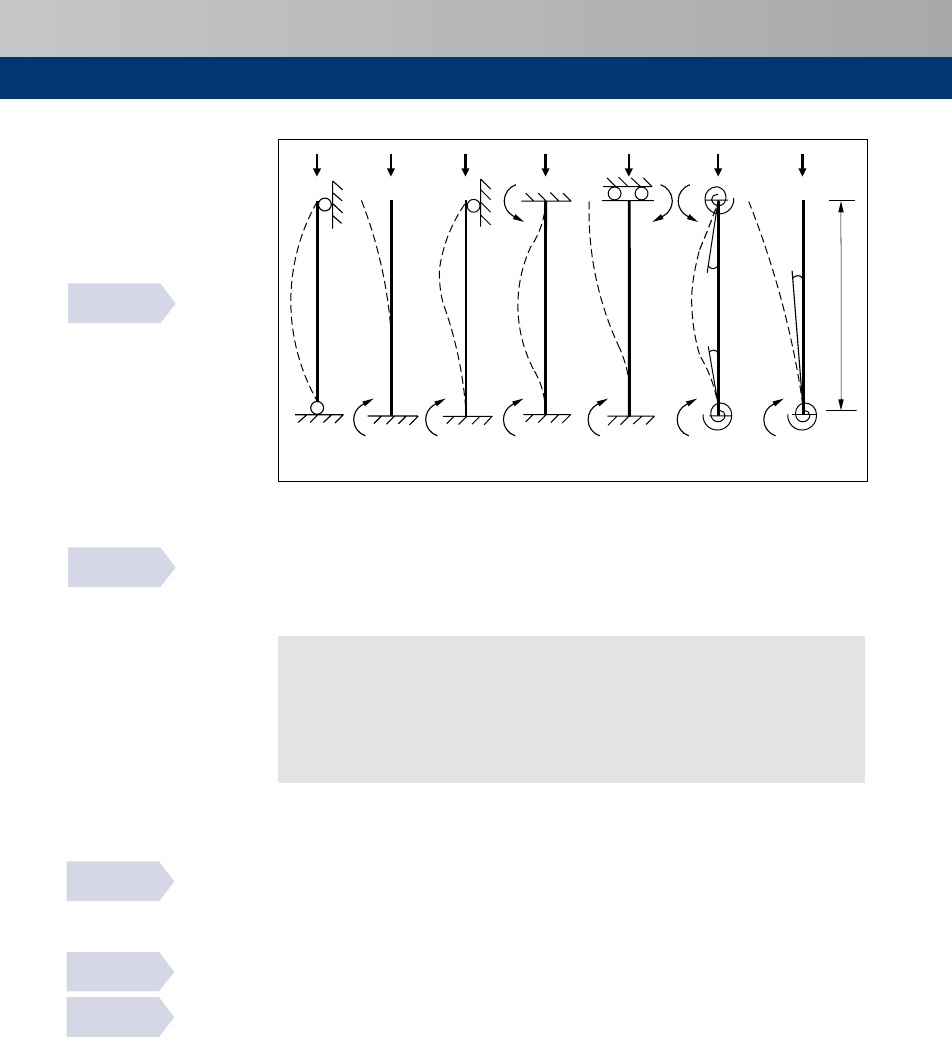
32
y
y
y
a) l
0
= l b) l
0
= 2l c) l
0
= 0.7l d) l
0
= l/2 e) l
0
= l f) l/2 < l
0
< l g) l
0
> 2l
Figure 5.6
Examples of different buckling modes and corresponding effective lengths for isolated members
Slenderness ratio, l
Slendernessratiol=
0
/
where
=theradiusofgyrationoftheuncrackedconcretesection
Ignoringreinforcement:
l=3.46
0
/forrectangularsections
=4.0
0
/forcircularsections
where
=thedepthinthedirectionunderconsideration
=thediameter
Limiting slenderness ratio l
lim
The limiting slendernessratio, l
lim
, abovewhich second order effects should beconsidered,
isgivenby
l
lim
=20/
0.5
where
= 1/(1+0.2h
ef
)(ifh
ef
isnotknownmaybetakenas0.7)
where
h
ef
= effectivecreepfactor=h(∞,
0
)
0Eqp
/
0Ed
h(∞,
0
) = finalcreepcoefficient(seeSection3.1.2)
0Eqp
= thefirstorderbendingmomentinthequasi-permanentload
combination(SLS)
0Ed
= thefirstorderbendingmomentindesignloadcombination(ULS)
= (1+2w)
0.5
(ifwisnotknownmaybetakenas1.1)
where
w = mechanicalreinforcementratio
=(
s
/
c
)(
yd
/
cd
)
s
=totalareaoflongitudinalreinforcement
= 1.7–
m
(If
m
isnotknown,maybetakenas0.7
where
m
=
01
/
02
,where
01
and
02
arethefirstorderendmomentsatULSwith
02
numericallylargerthan
01
.If
01
and
02
givetensiononthesame
sidethen
m
ispositive(and<1.7),seeFigure5.7
m
= 1.0forunbracedmembersandbracedmembersinwhichthefirstorder
momentsarecausedlargelybyimperfectionsortransverseloading
BS EN 1992-1-1
5.8.3.2(1)
BS EN 1992-1-1
fig. 5.7
BS EN 1992-1-1
5.8.3.1(1) & NA
BS EN 1992-1-1
5.8.4
BS EN 1992-1-1
3.1.4(4), 3.1.4(5)

33
Structuralanalysis
Table 5.1
Effective height, l
0
for columns
Case Idealized column and buckling mode Restraints Effective
height l
0
Location Position Rotation
1
l
Top Full
Full
a
0.70
Bottom Full
Full
a
2
l
Top Full None
0.85
Bottom Full
Full
a
3
l
Top Full None
1.0
Bottom Full None
4
Elastometric
bearing
b
l
Top
None
c
None
c
1.3
Bottom Full
Full
a
5
l
Top None None
1.4
Bottom Full
Full
a
6
l
Top None
Full
a
1.5
Bottom Full
Full
a
7
or
l l
Top None None
2.3
Bottom Full
Full
d
Notes
Theheightofthebearingsisnegligiblecomparedwiththatofthecolumn.
Key
a Rotationalrestraintisatleast4(
)/,where()istheflexuralrigidityofthecolumn
b Mayalsobeusedwithrollerbearingsprovidedthattherollersareheldinplacebyaneffectivemeans,suchasracks
c Lateralandrotationalrigidityofelastomericbearingsarenegligible
d Rotationalrestraintisatleast8()/l,where()istheflexuralrigidityofthecolumn
PD 6687-2
table 1

34
=
Ed
/(
c
cd
)
where
Ed
=designvalueofaxialforce
Note:h
ef
maybetakenas0ifallthefollowingconditionsaremet:
h(∞,
0
) ≤2.0;
l ≤75;and
0Ed
/
Ed
≥,thedepthofthecross-sectionintherelevantdirection.
Figure 5.7
Values of C
for different
values of r
m
a) C = 0.7, r
m
= 1.0 b) C = 1.7, r
m
= 0 c) C = 2.7, r
m
= – 1.0
01
=
02
02
02
02
01
=–
02
0
Design bending moments
Non-slender columns
Whenl≤l
lim
i.e.whennon-slender,thedesignbendingmomentinacolumnis
Ed
=
02
where
Ed
= designmoment
02
,
01
= firstorderendmomentsatULSincludingallowancesforimperfections.
02
isnumericallylargerthan
01
.Attentionshouldbepaidtothesign
ofthebendingmoments.Iftheygivetensiononthesameside,
01
and
02
shouldhavethesamesign
02
= +
i
Ed
where
= largestmomentfromfirstorderanalysis(elasticmomentswithout
redistribution)andignoringeffectofimperfections
Ed
= designvalueofaxialforce
i
= eccentricityduetoimperfections=y
i
0
/2
Forcolumnsinbracedsystems
i
=
0
/400(i.e.y
i
=/200formostbracedcolumns).Thedesign
eccentricityshouldbeatleast(/30)butnotlessthan20mm.
where
y = inclinationusedtorepresentimperfections
0
= effectivelengthofcolumn
= depthofthesectionintherelevantdirection
Slender columns (nominal curvature method)
Thismethodisprimarilysuitableforisolatedmemberswithconstantnormalforceandadefined
effectivelength
0
.Themethodgivesanominalsecondordermomentbasedonadeflection,
whichinturnisbasedontheeffectivelengthandanestimatedmaximumcurvature.
Other
methodsareavailableinBSEN1992-1-1.
Thedesignmomentis:
Ed
=
0Ed
+
2
where
BS EN 1992-1-1
5.8.3.1(1) & NA
BS EN 1992-1-1
5.8.8.1(1)
BS EN 1992-1-1
5.8.3.1(1)
BS EN 1992-1-1
5.2.7
BS EN 1992-1-1
6.1(4)
BS EN 1992-1-1
5.8.3.2(3)
BS EN 1992-1-1
5.8.8.2(1)
5.6.2
BS EN 1992-1-1
5.8.4(4)
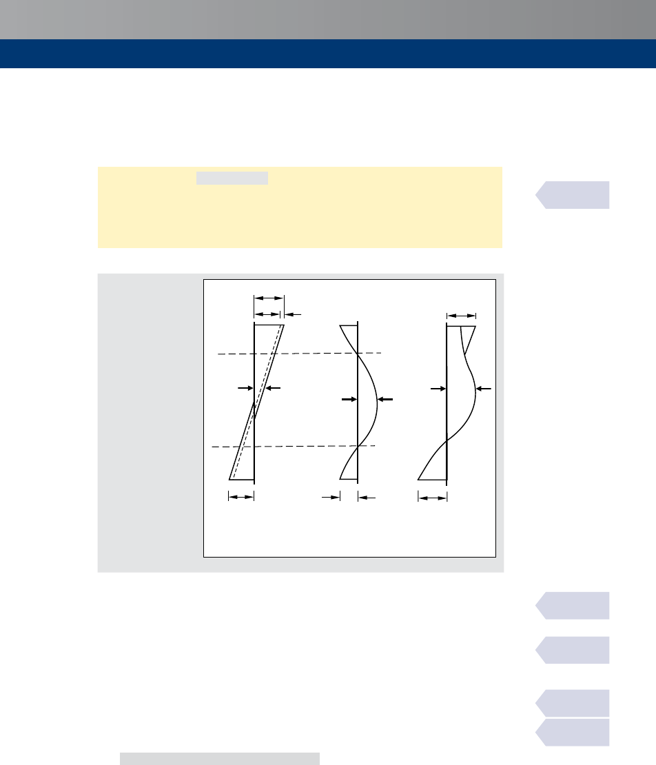
35
Structuralanalysis
0Ed
= firstordermoment,includingtheeffectofimperfections(andmaybetakenas
0E
)
2
= nominalsecondordermoment
Themaximumvalueof
Ed
isgivenbythedistributionsof
0Ed
and
2
;thelattermaybetaken
asparabolicorsinusoidalovertheeffectivelength.
Forbracedstructures
(seeFigure5.8):
Ed
=MAX{
0e
+
2
;
02
;
01
+0.5
2
}
Forunbracedstructures:
Ed
=
02
+
2
Formomentswithoutloadsappliedbetweentheirends,differingfirstorderendmoments
01
and
02
(seeabove)maybereplacedbyanequivalentfirstorderendmoment
0e
:
0e
=0.6
02
+0.4
01
≥0.4
02
Thenominalsecondordermoment
2
is
2
=
Ed
2
where
Ed
= designvalueofaxialforce
2
= deflection
= (/)
o
2
/
= curvature=
r
h
(
yd
/(
s
0.45))
r
= (
u
–)/(
u
–
bal
)≤1.0
Note:
r
maybederivedfromcolumncharts.
u
= 1+w
w = mechanicalreinforcementratio
=(
s
/
c
)(
yd
/
cd
)asinSection5.6.1above
=
Ed
/
c
cd
asdefinedinSection5.6.1above
bal
= valueofatmaximummomentofresistanceandmaybetakenas0.4
h
=1+bh
ef
≥
1.0
b = 0.35+(
ck
/200)–(l/150)
l = slendernessratio
0
/
PD 6687-1
2.11
BS EN 1992-1-1
5.8.8.2(2)
BS EN 1992-1-1
5.8.8.2(3)
BS EN 1992-1-1
5.8.8.2(4)
BS EN 1992-1-1
5.8.8.3
Figure 5.8
Moments in
braced columns
+
=
a) First order
moments for
non-slender columns
b) Additional second
order moments for
slender columns
c) Total moment
diagram for
slender columns
2
=
Ed
2
02
02
1
Ed
0e
0e
+
2
01
0.5
2
01
+0.5
2

36
= radiusofgyrationoftheuncrackedconcretesection
h
ef
= effectivecreepcoefficientasdefinedinSection5.6.1
0
= effectivelengthofcolumn
s
= 200GPa
= factordependingonthecurvaturedistribution(seebelow)
Forconstantcrosssection,=10(≈p
2
)isnormallyused.Ifthefirstordermomentisconstant,a
lowervalueshouldbeconsidered(8isalowerlimit,correspondingtoconstanttotalmoment).
Biaxial bending
Separatedesignineachprincipaldirection,disregardingbiaxialbending,maybeundertakenas
afirststep.Nofurthercheckisnecessaryif:
0.5 ≤ l
y
/l
z
≤2.0and,forrectangularsections,and
0.2 ≥ (
y
/
eq
)/(
z
/
eq
)≥5.0
where
l
y
,l
z
= slendernessratios
0
/withrespecttothey-andz-axes
y
=
Edy
/
Ed
eq
= 3.46
z
(=forrectangularsections)
z
=
Edz
/
Ed
eq
= 3.46
y
(=forrectangularsections)
where
Ed
= designvalueofaxialforce
Edy
,
Edz
=designmomentintherespectivedirection.(Momentsdueto
imperfectionsneedbeincludedonlyinthedirectionwheretheyhave
themostunfavourableeffect.)
Note:forsquarecolumns(
y
/
eq
)/(
z
/
eq
)=
Edy
/
Edz
Ifthisconditionisnotsatisfied,andintheabsenceofanaccuratecross-sectiondesignforbiaxial
bending,thefollowingsimplifiedcriterionmaybeused:
(
Edz
/
Rdz
)
+(
Edy
/
Rdy
)
≤1.0
where
Rdy
,
Rdz
= designmomentaroundtherespectiveaxisincludingsecondordermoment
inthedirectionwhereitwillgivethemostunfavourableeffect.
= anexponent:forcircularorellipticalsections,=2.0,forrectangular
sections,interpolatebetween
= 1.0for
Ed
/
Rd
=0.1
= 1.5for
Ed
/
Rd
=0.7
= 2.0for
Ed
/
Rd
=1.0
Corbels
Definition
Corbelsareshortcantileversprojectingfromcolumnsorwallswiththeratioofshearspan
(i.e.thedistancebetweenthefaceoftheappliedloadandthefaceofthesupport)tothe
depthofthecorbelintherange0.5to2.0.
5.6.3
5.7
5.7.1
BS EN 1992-1-1
5.8.9(2)
BS EN 1992-1-1
5.8.9(3)
BS EN 1992-1-1
5.8.9(2)
BS EN 1992-1-1
5.8.9(4)
BS EN 1992-1-1
3.2.7(4)
BS EN 1992-1-1
5.8.8.2(4)

37
StructuralanalysisStructuralanalysis
Analysis
Corbels(
c
<
0
)maybedesignedusingstrutandtiemodels(seeFigure5.9)
orasshortbeams
designedforbendingandshear.
Theinclinationofthestrutislimitedby1.0≤tany≤2.5.
If
c
≤0.5
c
closedhorizontalorinclinedlinkswith
s,lnk
≥0.5
s,main
shouldbeprovidedin
additiontothemaintensionreinforcement(seeFigure5.10a).
If
c
>0.5
c
and
Ed
>
Rd,c
(seeSection7.2.1)closedverticallinkswith
s,lnk
≥0.5
Ed
/
yd
shouldbeprovidedinadditiontothemaintensionreinforcement(seeFigure5.10b).
Themaintensionreinforcementshouldbeanchoredatbothends.Itshouldbeanchoredin
thesupportingelementonthefarfaceandtheanchoragelengthshouldbemeasuredfrom
the location of the vertical reinforcement in the near face.The reinforcement should be
anchoredinthecorbelandtheanchoragelengthshouldbemeasuredfromtheinnerfaceof
theloadingplate.
If there are special requirements for crack limitation, inclined stirrups at the re-entrant
openingcanbeeffective.
Thecheckofthecompressionstrutcaneffectivelybemadebylimitingtheshearstresssuch
that
Ed
≤0.5
w
v'
cd
where
v' =1–(
ck
/250)
cd
= a
cc
ck
/g
C
a
cc
=
0.85
Ed
td
Ed
H
Ed
0
c
y
s
Rd,max
c
wd
Key
wd
= designvalueofforce
instirrup
= tie
= compressionstrut
Figure 5.9
Corbel strut-and-tie model
PD 6687 B3
BS EN 1992-1-1
6.5.2(2)
PD 6687
fig. B4
5.7.2

38
5.8
A
s,main
Anchorage devices
or loops
Links
a) Reinforcement for a
c
≤ 0.5h
c
b) Reinforcement for a
c
> 0.5h
c
A
s,lnk
≥
k
1
A
s,main
SA
s,lnk
≥
A
s,main
Figure 5.10
Corbel detailing
Lateral instability of slender beams
Lateralinstabilityofslenderbeamsshallbetakenintoaccountwherenecessary,e.g.forprecast
beamsduringtransportanderection,forbeamswithoutsufficientlateralbracinginthefinished
structureetc.Geometricimperfectionsshallbetakenintoaccount.Alateraldeflectionof/300
should be assumed as a geometric imperfection in the verification of beams in unbraced
conditions, with = total length of beam. In finished structures, bracing from connected
membersmaybetakenintoaccount
Second order effects in connection with lateral instability may be ignored if the following
conditionsarefulfilled:
persistentsituations:
0t
/≤50/()
1/3
and/≤2.5
transientsituations:
0t
/≤70/()
1/3
and/≤3.5
where
0t
=distancebetweentorsionalrestraints
= totaldepthofbeamincentralpartof
0t
= widthofcompressionflange
Torsionassociatedwithlateralinstabilityshouldbetakenintoaccountinthedesignof
supportingstructures.
PD 6687
fig. B5
BS EN 1992-1-1
5.9

39
Bendingandaxialforce
Bending and axial force
Assumptions
Indeterminingtheresistanceofsections,thefollowingassumptionsaremade.
Planesectionsremainplane.
Straininthebondedreinforcement,whetherintensionorcompression,isthesameasthat
inthesurroundingconcrete.
Tensilestrengthoftheconcreteisignored.
RectangularstressdistributioninthesectionisasshowninFigure6.1.Otherstress–strain
relationshipsaregiveninBSEN1992-1-1Cl.3.1.7.
StressesinreinforcementarederivedfromFigure6.2.Theinclinedbranchofthedesignline
maybeusedwhenstrainlimitsarechecked.
Forsectionsnotfullyincompression,thecompressivestraininconcreteshouldbelimited
toe
cu2
(seeFigure6.3).
Forsectionsinpureaxialcompression,thecompressivestraininconcreteshouldbelimited
toe
c2
(seeFigure6.3).
Forsituationsintermediatebetweenthesetwoconditions,thestrainprofileisdefinedby
assumingthatthestrainise
c2
athalfthedepthofthesection(seeFigure6.3).
ExpressionsderivedfromFigures6.1to6.3areprovidedinSection17.
Table 6.1
Values for
n and l when f
ck
> 50
f
ck
e
cu3
a
n
b
l
c
55
0.00313 0.98 0.79
60
0.00288 0.95 0.78
70
0.00266 0.90 0.75
Key
a e
cu3
(%)=2.6+35[(90–
ck
)/100]
4
b n =1–(
ck
–50)/200
c
l =0.8–(
ck
–50)/400
BS EN 1992-1-1
fig. 6.1
BS EN 1992-1-1
3.1.7(3), fig. 3.5
BS EN 1992-1-1
6.1(2)
BS EN 1992-1-1
fig. 3.5
6
6.1
e
cu3
yd
s
c
n
cd
c
l
s
e
s
For
ck
≤ 50MPa,e
cu3
=0.0035,n =1andl=0.8.ForotherconcreteclassesseeTable6.1
= neutralaxisdepth
c
(
s
) = forceinconcrete(steel)
e
cu3
= ultimatecompressivestraininconcrete = effectivedepth
e
s
= tensilestraininreinforcement = leverarm
Figure 6.1
Rectangular stress distribution

40
e
uk
Idealised
Design
Strain,
e
Stress, s
e
ud
yk
yk
yd
=
yk
/g
S
yk
/
g
S
yk
yd
/
s
BS EN 1992-1-1
fig. 3.8
Where
= (
t
/
y
)
k
(SeeTable3.3)
yk
= characteristicyieldstrengthofreinforcement
yd
= designyieldstrengthofreinforcement
t
= tensilestrengthofreinforcement
g
S
= partialfactorforreinforcingsteel=
1.15
e
ud
= designstrainlimitforreinforcing
steel=
0.9e
uk
e
uk
= characteristicstrainofreinforcementat
maximumforce(seeTable3.3)
Figure 6.2
Idealised and design stress–strain diagrams for reinforcing steel (for tension and compression)
e
p(0)
e
ud
e
c2
e
cu2
(e
cu3
)
(e
c3
)
e
s
,e
p
De
p
e
c
e
y
s2
p
s1
0
a) Section b) Strain
(1–e
c2
/e
cu2
)
or
(1–e
c3
/e
cu3
)
Concretecompression
strainlimit
Concretepure
compression
strainlimit
Reinforcingsteel
tensionstrain
limit
Where
s1
= areaofreinforcingsteelinlayer1
p
= areaofprestressingsteel
= effectivedepth
= overalldepthofsection
e
c
= compressivestraininconcrete
e
s
= straininreinforcingsteel
e
p(0)
= initialstraininprestressingsteel
De
p
= changeinstraininprestressingsteel
e
ud
= designstrainlimitforreinforcingsteelintension
e
c3
= compressivestrainlimitinconcreteforconcreteinpureaxialcompressionassuming
bilinearstress–strainrelationship(seeFigure3.4ofBSEN1992-1-1).
e
c3
(‰) =1.75for
ck
≤50MPa
e
c3
(‰) =1.75+0.55[(
ck
–50)/40]for
ck
>50MPa
e
cu2
= (=e
cu3
)compressivestrainlimitinconcretenotfullyinpureaxialcompression
e
cu3
(‰)=3.5for
ck
≤50MPa.
e
cu3
(‰) = 2.6+0.35[(90–
ck
)/100]
4
for
ck
>50MPa
e
y
= reinforcementyieldstrain
Figure 6.3
Possible strain distributions in the ultimate limit state
BS EN 1992-1-1
fig. 6.1

41
Shear
Shear
General
Definitions
Fortheverificationoftheshearresistancethefollowingsymbolsaredefined:
Rd,c
= designshearresistanceofamemberwithoutshearreinforcement
Rd,s
= designvalueoftheshearforcethatcanbesustainedbytheyieldingshear
reinforcement
Rd,max
= designvalueofthemaximumshearforcethatcanbesustainedbythemember,
limitedbycrushingofthecompressionstruts
Theseresisttheappliedshearforce,
Ed
.
Requirements for shear reinforcement
If
Ed
≤
Rd,c
, no calculated shear reinforcement is necessary. However, minimum shear
reinforcementshouldstillbeprovided(seeSection15.2.6)exceptin:
Slabs,whereactionscanberedistributedtransversely.
Membersofminorimportance,whichdonotcontributesignificantlytotheoverall
resistanceandstabilityofthestructure(e.g.lintelswithaspanoflessthan2m).
If
Ed
>
Rd,c
shear reinforcementis required such that
Rd,s
>
Ed
.The resistance of the
concretetoactasastrutshouldalsobechecked.
Inmemberssubjectpredominantlytouniformlydistributedloading,thefollowingapply:
Shearatthesupportshouldnotexceed
Rd,max
.
Requiredshearreinforcementshouldbecalculatedatadistance fromthefaceofthe
supportandcontinuedtothesupport.
Thelongitudinaltensionreinforcementshouldbeabletoresisttheadditionaltensileforce
causedbyshear(seeSection15.2.2).
TheUKNAlimitsshearstrengthofconcretehigherthanC50/60tothatofC50/60.
Shear and transverse bending
Duetothepresenceofcompressivestressfieldsarisingfromshearandbending,theinteraction
betweenlongitudinalshearandtransversebendinginthewebsofboxgirdersectionsshouldbe
consideredinthedesign.When
Ed
Rd,max
<0.2or
Ed
/
Rd,max
<0.1,thisinteractioncanbe
disregarded(where
Rd,max
and
Rd,max
representrespectivelythemaximumwebcapacityfor
longitudinalshearandtransversebending).
Furtherinformationontheinteractionbetweenshearandtransversebendingmaybefoundin
AnnexMMofBSEN1992-2.
Resistance of members not requiring shear reinforcement
General situation
Thedesignvaluefortheshearresistanceisgivenby:
Rd,c
=[(
0.18
/g
C
)(100r
l
ck
)
1/3
+
0.15
s
cp
]
w
≥(
0.035
1.5
ck
0.5
+
0.15
s
cp
)
w
BS EN 1992-1-1
6.2.1(1)
BS EN 1992-1-1
6.2.1(3)
BS EN 1992-1-1
6.2.1(4)
BS EN 1992-1-1
6.2.1(5)
BS EN 1992-1-1
6.2.1(8)
BS EN 1992-1-1
6.2.1(7)
BS EN 1992-2
3.1.2(2) & NA
BS EN 1992-2
6.2.106 (101)
BS EN 1992-2
6.2.2(101) & NA
7
7.1
7.1.1
7.1.2
7.1.3
7.2
7.2.1

42
where
= 1+(200/)
0.5
≤2.0(inmm;seeTable7.1)
g
C
=
0.15
r
l
=
sl
/(
w
)≤0.02
where
sl
=areaofthetensilereinforcementextendingatleast
bd
+beyondthesection
considered(seeFigure7.1);theareaofbondedprestressingsteelmaybeincludedin
thecalculationof
sl
.Inthiscaseaweightedmeanvalueofmaybeused.
bd
=designanchoragelength
w
=smallestwidthofthecross-sectioninthetensilearea
s
cp
=
Ed
/
c
<0.2
cd
(MPa)
where
Ed
= axialforceinthecross-sectionduetoloadingorprestressinginnewtons
(
Ed
>0forcompression).Theinfluenceofimposeddeformationson
Ed
maybeignored.
C
= areaofconcretecross-section(mm
2
)
Table 7.1
V
Rd,c '
shear resistance without shear reinforcement where s
cp
= 0 (MPa)
r
l
= A
s
/(bd) Effective depth d (mm)
≤200 225 250 275 300 350 400 450 500 600 750
0.25%
0.54 0.52 0.50 0.48 0.47 0.45 0.43 0.41 0.40 0.38 0.36
0.50%
0.59 0.57 0.56 0.55 0.54 0.52 0.51 0.49 0.48 0.47 0.45
0.75%
0.68 0.66 0.64 0.63 0.62 0.59 0.58 0.56 0.55 0.53 0.51
1.00%
0.75 0.72 0.71 0.69 0.68 0.65 0.64 0.62 0.61 0.59 0.57
1.25%
0.80 0.78 0.76 0.74 0.73 0.71 0.69 0.67 0.66 0.63 0.61
1.50%
0.85 0.83 0.81 0.79 0.78 0.75 0.73 0.71 0.70 0.67 0.65
1.75%
0.90 0.87 0.85 0.83 0.82 0.79 0.77 0.75 0.73 0.71 0.68
≥ 2.00%
0.94 0.91 0.89 0.87 0.85 0.82 0.80 0.78 0.77 0.74 0.71
k 2.000 1.943 1.894 1.853 1.816 1.756 1.707 1.667 1.632 1.577 1.516
Notes
1 TablederivedfromBSEN1992-1-1andtheUKNationalAnnex.
2 Tablecreatedfor
ck
=30MPaassumingverticallinks.
3 Forr
l
≥0.4%and
ck
= 25MPa,applyfactorof0.94
ck
= 45MPa,applyfactorof1.14
ck
= 35MPa,applyfactorof1.05
ck
≥ 50MPa,applyfactorof1.19
ck
= 40MPa,applyfactorof1.10
Uncracked regions in prestressed members
Inprestressedsingle-spanmemberswithoutshearreinforcement,theshearresistanceofthe
regionscrackedinbendingmaybecalculatedusingtheExpressioninSection7.2.1.Inregions
uncrackedin bending(where the flexural tensile stress is smaller than
ctk,0.05
/g
C
) the shear
resistanceshouldbelimitedbythetensilestrengthoftheconcrete.Intheseregionstheshear
resistanceisgivenby:
Rd,c
=(
w
)(
ctd
2
+a
l
s
cp
ctd
)
0.5
where
= secondmomentofarea
w
= widthofthecross-sectionatthecentroidalaxis,allowingforthepresenceofducts
(seebelow)
BS EN 1992-1-1
6.2.2(2)
7.2.2

43
Shear
= firstmomentofareaaboveandaboutthecentroidalaxis
a
l
=
x
pt2
≤1.0forpretensionedtendons
= 1.0forothertypesofprestressing
x
= distanceofsectionconsideredfromthestartingpointofthetransmissionlength
pt2
= upperboundvalueofthetransmissionlengthoftheprestressing(Seesection14.6)
s
cp
= concretecompressivestressatthecentroidalaxisduetoaxialloadingand/or
prestressing(s
cp
=
Ed
c
inMPa,
Ed
>0incompression)
Alternatively,wherethereisnoaxialforce,includingprestressing
Rd,c
=
w
Rd,c
with
Rd,c
availablefromTable7.1
Inmostpracticalcasesif
Ed
<
Rd,c
shearreinforcementwillnotberequired
where
Ed
=shearstressforsectionswithoutshearreinforcement=
Ed
/
w
.
Rd,c
maybeinterpolatedfromTable7.1.
Short span shear enhancement
TheapproachinBSEN1992-1-1ofapplyingareductionfactortotheloadisnotsuitable
forcaseswithmultiple,indirectordistributedloads.Therefore,intheNAtoBSEN1992-2,
theexpressionfor
Rd,c
hasbeenmodifiedfromtherecommendedvaluesothattheeffects
ofshearenhancementaretakenintoaccountthroughincreasingtheshearresistanceof
membersneartosupports.SeeFigure7.2.
Formemberswithactionsappliedatadistancea
v
where0.5≤a
v
≤2:
k
g
C
(100r
1
f
ck
)
b
+ 0.15s
cp
V
Rd,c
=
0.18
a
v
2d
[]
b
w
d
providedthattheshearforce,
Ed
,isnotmultipliedbyb(BSEN1992-1-1,Cl.6.2.2(6))andthe
longitudinalreinforcementisfullyanchoredatthesupport.
Figure 7.1
Definition of A
sl
a) End support
b) Internal support
Section
considered
Section
considered
Section
considered
45º
45º
sl
sl
sl
bd
bd
bd
Ed
Ed
Ed
45º
BS EN 1992-2
fig. 6.3
BS EN 1992-2
NA 6.2.2(101)
PD 6687-2
7.2.2
7.2.3

44
Figure 7.2
Loads near supports
b) Corbel
v
a) Beam with direct support
v
Resistance of members requiring shear reinforcement
Basis
ThedesignofmemberswithshearreinforcementisbasedonthetrussmodelshowninFigure
7.3.
AsimplifiedversionofthisdiagramisshowninFigure7.4.
b) Web thickness b
w
w
w
a) Truss model
td
Tensilechord
Shearreinforcement
Compressionchord
Struts
cd
(coty–cota)
y
a
z=0.9
az
az
Figure 7.3
Truss model and notation for shear reinforced members
Figure 7.4
Variable strut angle, y
Concretestrutincompression
Longitudinalreinforcementintension
Verticalshearreinforcement
y
BS EN 1992-2
fig. 6.5
BS EN 1992-1-1
6.2.3
7.3
7.3.1
BS EN 1992-1-1
fig. 6.4
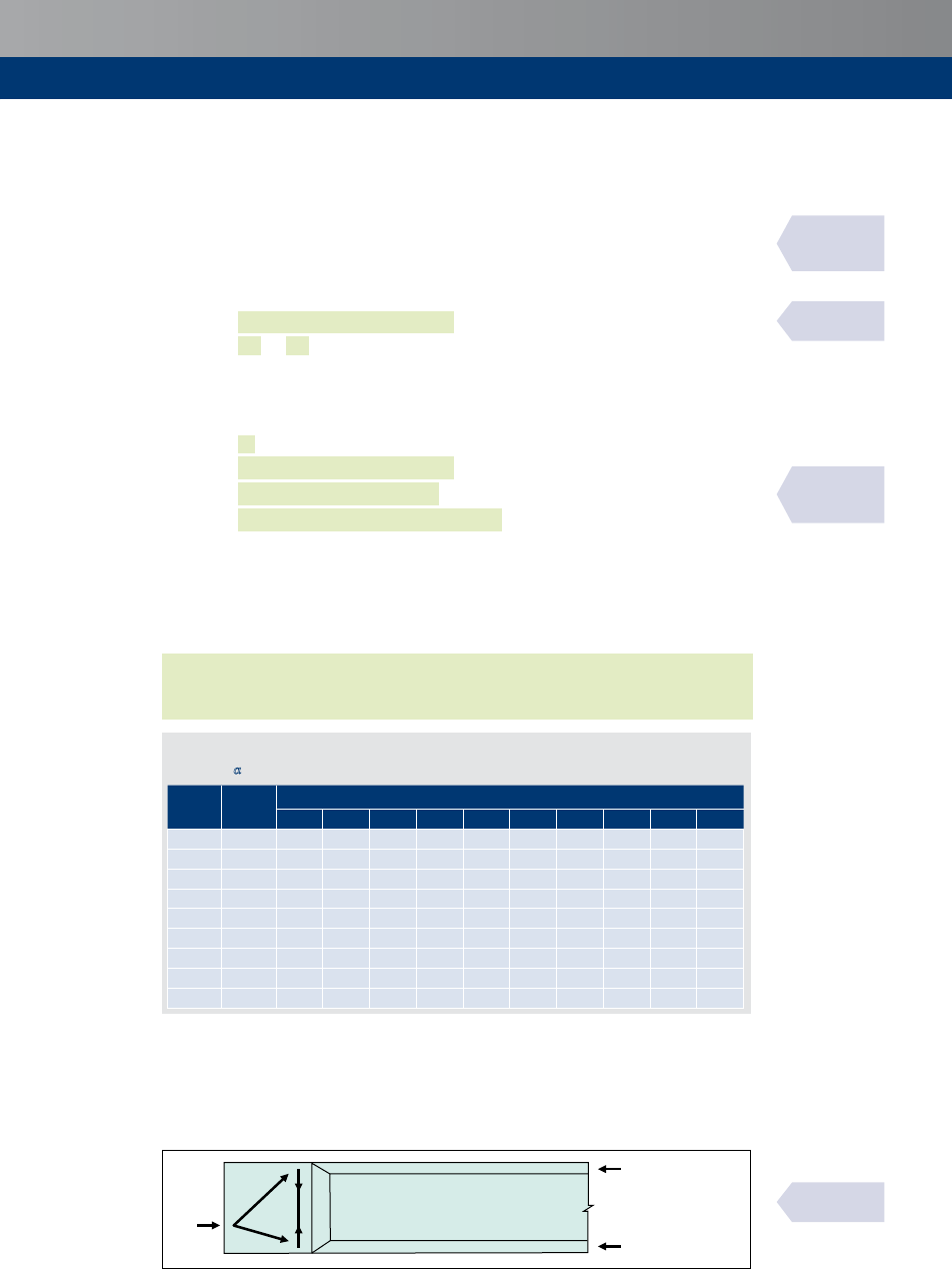
45
Shear
Shear resistance check
Theresistanceoftheconcretesectiontoactasastrut
Rd,max
shouldbecheckedtoensurethat
itequalsorexceedsthedesignshearforce,
Ed
i.e.ensurethat:
Rd,max
= a
cw
w
v
1
cd
(coty+tany)≥
Ed
withverticallinks
= a
cw
w
v
1
cd
(coty+cota)/(1+cot
2
y)≥
Ed
withinclinedlinks
where
= leverarm(SeeSection7.3.3)
v
1
=
0.6[1–(
ck
/250)](1–0.5cosa)
cd
=
1.0
ck
/
1.5
y = angleofinclinationofthestrut,suchthatcotyliesbetween1.0and2.5.
a = angleofinclinationofthelinkstothelongitudinalaxisForverticallinkscota=0.
a
cw
= coefficienttakingaccountofthestateofthestressinthecompressionchord(see
Table7.2)
=
1
fornon-prestressedstructures
=
(1+s
cp
/
cd
)for0<s
cp
≤0.25
cd
=
1.25for0.25
cd
<s
cp
≤0.5
cd
=
2.5(1–s
cp
/
cd
)for0.5
cd
<s
cp
<1.0
cd
where
s
cp
=meancompressivestress,measuredpositive,intheconcreteduetothedesign
axialforce.
s
cp
shouldbeobtainedbyaveragingitovertheconcretesectiontakingaccountofthereinforcement.The
valueofs
cp
neednotbecalculatedatadistancelessthan0.5cotyfromtheedgeofthesupport.
Thevaluesofv
1
anda
cw
shouldnotgiverisetoavalueof
Rd,max
greaterthan200
w
2
at
sectionsmorethanadistancefromtheedgeofasupport.Forthispurpose,thevalueof
w
doesnotneedtobereducedforducts.
Table 7.2
Values for a
cw
f
ck
f
cd
Mean compressive stress, s
cp
0 0.5 1 2 3 4 5 10 20 30
20 13.3
1 1.04 1.08 1.15 1.23 1.25 1.25 0.63 — —
25 16.7
1 1.03 1.06 1.12 1.18 1.24 1.25 1.00 — —
30 20.0
1 1.03 1.05 1.10 1.15 1.20 1.25 1.25 — —
35 23.3
1 1.02 1.04 1.09 1.13 1.17 1.21 1.25 0.36 —
40 26.7
1 1.02 1.04 1.08 1.11 1.15 1.19 1.25 0.63 —
45 30.0
1 1.02 1.03 1.07 1.10 1.13 1.17 1.25 0.83 —
50 33.3
1 1.02 1.03 1.06 1.09 1.12 1.15 1.25 1.00 0.25
60 40.0
1 1.01 1.03 1.05 1.08 1.10 1.13 1.25 1.25 0.63
70 46.7
1 1.01 1.02 1.04 1.06 1.09 1.11 1.21 1.25 0.89
Inthecaseofstraighttendons,ahighlevelofprestress(s
cp
/
cd
>0.5)andthinwebs,ifthe
tensionandthecompressionchordsareabletocarrythewholeprestressingforceandblocksare
providedattheextremityofbeamstodispersetheprestressingforce(seeFigure7.5),itmaybe
assumedthattheprestressingforceisdistributedbetweenthechords.Inthesecircumstances,
thecompressionfieldduetoshearonlyshouldbeconsideredintheweb(a
cw
=1).
P
d
P
d,t
P
d,c
P
d
= P
d,c
+
P
d,t
Figure 7.5
Dispersion of prestressing by end blocks within the chords
BS EN 1992-2
6.2.3(103)
& NA
BS EN 1992-2
6.2.3(103) & NA
BS EN 1992-2
fig. 6.101
7.3.2
BS EN 1992-1-1
Exp. (6.9) Exp.
(6.14) & NA

46
Themaximumeffectivecross-sectionalareaoftheshearreinforcement
sw,max
forcoty=1is
givenby:
aa
cw
v
1
f
cd
A
sw,max
f
ywd
b
w
s
≤
Lever arm, z
Intheshearanalysisofreinforcedconcrete,theapproximatevalue=0.9maynormallybe
used.
Thisisnotappropriatewhen:
Thereisanaxialforceorprestress,or
Thewidthatthecentroidisgreaterthantheminimumcross-sectionwidthin
compression,or
Thecross-sectionhasatensionflangebutnocompressionflange
Insuchcasestheleverarmshouldbedeterminedbasedonananalysisofthesection.
Shear reinforcement required, A
sw
/s
The cross-sectional area of the shear reinforcement required is calculated using the shear
resistance:
Rd,s
=(
sw
/)
ywd
(coty+cota)sina≤
Rd,max
where
sw
= cross-sectionalareaoftheshearreinforcement.(For
sw,min
seeSection15.2.6)
= spacingofthestirrups
= leverarm(SeeSection7.3.3)
ywd
=
ywk
/g
S
=designyieldstrengthoftheshearreinforcement
a = angleofthelinkstothelongitudinalaxis
Forverticallinks,cota=0andsina=1.0,and:
sw
/≥
Ed
/(
ywd
coty)
Webs containing metal ducts
Wherethewebcontainsgroutedmetalductswithadiameterf>
w
/8theshearresistance
Rd,max
shouldbecalculatedonthebasisofanominalwebthicknessgivenby:
w,nom
=
w
–0.5SfwherefistheouterdiameteroftheductandSfisdeterminedforthe
mostunfavourablelevel.
Forgroutedmetalductswithf≤
w
/8,
w,nom
=
w
Fornon-groutedducts,groutedplasticductsandunbondedtendonsthenominalwebthicknessis:
w,nom
=
w
–1.2Sf
Thevalue1.2isintroducedtotakeaccountofsplittingoftheconcretestrutsduetotransverse
tension.Ifadequatetransversereinforcementisprovidedthisvaluemaybereducedto1.0.
Additional tensile forces
Theadditionaltensileforce,D
td
,inthelongitudinalreinforcementduetoshear
Ed
maybe
calculatedfrom:
D
td
=0.5
Ed
(coty–cota)
Ed
/z+D
td
shouldbetakenasnotgreaterthan
Ed,max
/z
BS EN 1992-1-1
Exp. (6.15)
BS EN 1992-1-1
Exp. (6.13)
PD 6687-2
7.2.4.1
BS EN 1992-1-1
6.2.3(1)
BS EN 1992-1-1
Exp. (6.8)
BS EN 1992-1-1
6.2.3(6)
BS EN 1992-1-1
Exp. (6.16)
BS EN 1992-1-1
Exp. (6.17)
BS EN 1992-1-1
Exp. (6.18)
7.3.3
7.3.4
7.3.5
7.3.6

47
Shear
where
Ed,max
=maximummomentalongthebeam
Thisadditionaltensileforcegivesrisetothe‘shift’ruleforthecurtailmentofreinforcement
(seeSection15.2).
Inthecaseofbondedprestressing,located withinthetensilechord,theresistingeffectof
prestressingmaybetakenintoaccountforcarryingthetotallongitudinaltensileforce.Inthe
case of inclined bonded prestressing tendons in combination with other longitudinal
reinforcement/tendonstheshearstrengthmaybeevaluated,byasimplification,superimposing
twodifferenttrussmodelswithdifferentgeometry(Figure7.6);aweightedmeanvaluebetween
y
1
andy
2
maybeusedforconcretestressfieldverificationwithExpression(6.9).
y
2
y
1
Figure 7.6
Superimposed resisting model for shear
Members with actions applied near bottom of section
Whereloadisappliednearthebottomofasection,sufficientshearreinforcementtocarrythe
load to the top of the section should be provided in addition to any shear reinforcement
requiredtoresistshear.
Shear between web and flanges of T-sections
Thelongitudinalshearstress,
Ed
,atthejunctionbetweenonesideofaflangeandthewebisdetermined
bythechangeofthenormal(longitudinal)forceinthepartoftheflangeconsidered,accordingto:
Ed
=D
d
/(
f
D)
where
f
= thicknessofflangeatthejunctions
D = lengthunderconsideration,seeFigure7.7
D
d
= changeofthenormalforceintheflangeoverthelengthD
A
A
F
d
F
d
S
f
b
eff
A
sf
h
f
F
d
+ DF
d
F
d
+ DF
d
Dx
b
w
y
f
Longitudinal bar
anchored beyond
this projected point
Compressive struts
Figure 7.7
Notations for the connection between flange and web
BS EN 1992-2
6.2.3(107)
BS EN 1992-2
fig. 6.102N
BS EN 1992-1-1
6.2.1(9)
BS EN 1992-2
6.2.4(103)
BS EN 1992-1-1
fig. 6.7
7.3.7
7.3.8

48
ThemaximumvaluethatmaybeassumedforDishalfthedistancebetweenthesectionwhere
themomentis0andthesectionwherethemomentismaximum.Wherepointloadsareapplied
thelengthDshouldnotexceedthedistancebetweenpointloads.
Alternatively,consideringalengthDofthebeam,thesheartransmittedfromthewebtothe
flangeis
Ed
D/andisdividedintothreeparts:oneremainingwithinthewebbreadthandthe
othertwogoingouttotheflangeoutstands.Itshouldbegenerallyassumedthattheproportion
of the force remaining within the web is the fraction
w
/
eff
of the total force.A greater
proportion may be assumed if the full effectiveflange breadth is not required to resistthe
bendingmoment.InthiscaseacheckforcracksopeningatSLSmaybenecessary.
Therateofchangeoftheflangeforcescanbeunderestimatediftheeffectsofwebshearon
theflangeforcesarenotincluded,particularlyforcompressionflanges.Thechordforcesas
determinedforthedesignofthewebreinforcementshouldthereforebeused.
Forcompressionflanges,
d
maybecalculatedasfollows:
d
=(
eff
–
w
)
cd
/(2
eff
)when
f
>
c
d
=(
eff
–
w
)
cd
f
/2 when
f
≤
c
where
c
=depthofthecompressionzone
cd
=totalforceinthecompressionchordofthesheartrussintheweb
Fortensionflanges,
d
maybecalculatedbydeterminingtheproportionofthetotaltension
chordforce,
td
,carriedineachsideoftheflange.
Thetransversereinforcementperunitlength
sf
f
maybedeterminedasfollows:
(
sf
yd
f
)≥
Ed
f
/coty
f
Topreventcrushingofthecompressionstrutsintheflange,thefollowingconditionshouldbesatisfied:
Ed
≤
0.6(1–
ck
/250)
cd
siny
f
cosy
f
where
cd
=
1.0
ck
/
1.5
Thepermittedrangeofthevaluesforcoty
f
are:
1.0
≤coty
f
≤
2.0
forcompressionflanges(45°≥y
f
≥26.5°)
1.0
≤coty
f
≤
1.25
fortensionflanges(45°≥y
f
≥38.6°)
If
Ed
islessthanorequalto
0.4
ctd
noextrareinforcementabovethatforflexureisrequired.
Longitudinaltensionreinforcementintheflangeshouldbeanchoredbeyondthestrutrequired
to transmit the force back to the web at the section where this reinforcement is required
(SeeSection(A–A)ofFigure7.7).
Interface shear between concretes placed at different times
Whencompositeactionisassumedbetweentwolayersofconcretecastatdifferenttimes,
itisnecessarytopreventslipbetweenthetwolayers.Thiswillresultinshearstressatthe
interface,whichshouldbeverified.Theforceattheinterfaceistheflangeforceinthenew
concretecausedbythebendingmomentonthecompositesection.
Theshearstress at theinterfacebetween concretecastatdifferenttimesshouldsatisfy the
following.
Edi
≤
Rdi
PD 6687-2,
7.2.5
BS EN 1992-1-1
6.2.4(4)
BS EN 1992-1-1
6.2.4(6)
BS EN 1992-1-1
6.2.5
7.3.9

49
Shear
where
Edi
=designvalueoftheshearstressintheinterfaceandisgivenby:
Edi
=b
Ed
/(
i
)
where
Ed
= transverseshearforce
= leverarmofthecompositesection
i
= widthoftheinterface(seeFigure7.8)
b = ratioofthelongitudinalforceinthenewconcreteandthetotallongitudinalforce
eitherinthecompressionortensionzone,bothcalculatedforthesectionconsidered
Rdi
=
ctd
+s
n
+r
yd
(sina +cosa)≤0.5
0.6(1–
ck
/250)
cd
where
thevaluesofanddependontheinterfacesurfaceandareshowninTable7.3
ctd
=
ctk,0.05
/
1.5
cd
=
1.0
ck
/
1.5
s
n
= stressnormaltotheinterfacenottobetakengreaterthan0.6
cd
r =
s
/
i
s
= areaofreinforcementcrossingtheinterfaceincludingordinaryshearreinforcement
(ifany),withadequateanchorageatbothsidesoftheinterface
i
= areaofthejoint
a =angleofreinforcementcrossingtheinterface(45°≤a ≤90°)
b
i
b
i
a) Double-T unit with toppingb) I-beam with topping
Figure 7.8
Examples of interfaces for shear
Table 7.3
Values of m and for various interfaces
Classification of interface surfaces
Friction coefficient,
m
Shear coefficient,
Very smooth: surface cast against steel,
plastic or smooth wooden moulds
0.5 0.10
Smooth: slipformed or extruded surface or
face untreated after vibration
0.6 0.20
Rough: a surface with at least 3 mm
roughness at 40 mm spacing
0.7 0.40
Whereasteppeddistributionoftransversereinforcementisused,thetotalresistancewithin
anybandofreinforcementshouldbenotlessthanthetotallongitudinalshearinthesame
length and the longitudinal shear stress evaluated at any point should not exceed the
resistanceevaluatedlocallybymorethan10%.
BS EN 1992-1-1
fig. 6.8
BS EN 1992-1-1
6.2.5(2)
PD 6687-2
7.2.6

50
8
8.1
8.1.1
8.1.2
8.2
8.2.1
Punching shear
General
Basis of design
Punching shearis a local shear failurearound concentrated loads on slabsand the most
commonsituationswherethepunchingshearrulesarerelevantinbridgeapplicationsarein
thedesignofpilecaps,padfootings,anddeckslabswhicharesubjectedtowheelloadsand
aroundsupportsinslabssupportedondiscretebearingsorcolumns.Theresultingstressesare
verifiedalongdefinedcontrolperimetersaroundtheloadedarea.Theshearforceactsoveran
area
eff
,whereisthelengthoftheperimeterand
eff
istheeffectivedepthoftheslab
takenastheaverageoftheeffectivedepthsintwoorthogonaldirections.
Design procedure
Atthecolumnperimeter,ortheperimeteroftheloadedarea,themaximumpunchingshear
stressshouldnotbeexceeded,
Ed
≤
Rd,max
.
Punchingshearreinforcementisnotnecessaryif
Ed
≤
Rd,c
Where
Ed
exceeds
Rd,c
forthecontrolsectionconsidered,punchingshearreinforcementshould
beprovidedaccordingtoSection8.5
where
Ed
= designvalueoftheappliedshearstress(seeSections8.2and8.3)
Rd,max
= designvalueofthemaximumpunchingshearresistance(seeSection8.6)along
thecontrolsectionconsidered
Rd,c
= designvalueofpunchingshearresistanceofaslabwithoutpunchingshear
reinforcement,alongthecontrolsectionconsidered(seeSection8.4)
Rd,cs
= designvalueofpunchingshearresistanceofaslabwithpunchingshear
reinforcement,alongthecontrolsectionconsidered(seeSection8.5)
Applied shear stress
General
Wherethesupport reactioniseccentricwithregardtothecontrolperimeter,themaximum
shearstressshouldbetakenas:
Ed
=b
Ed
/(
i
)
where
= meaneffectivedepth
= (
y
+
z
)/2
i
= lengthofthecontrolperimeterunderconsideration(seeSection8.3)
Ed
= designvalueofappliedshearforce
b = factordealingwitheccentricity
y
= effectivedepthiny-direction
z
= effectivedepthinz-direction
BS EN 1992-1-1
6.4.3(1)
BS EN 1992-1-1
6.4.3(3)
BS EN 1992-1-1
6.4.3(2)
BS EN 1992-1-1
6.4.1

51
Punchingshear
8.2.2
8.2.3
Values of b (conservative values from diagram)
Forbracedstructures,whereadjacentspansdonotdifferbymorethan25%,thevaluesof
bshowninFigure8.1maybeused.
Cornercolumn
Edgecolumn
Internalcolumn
b
=1.5
b
=1.4
b
=1.15
Figure 8.1
Recommended
values for b
Values of b (using calculation method)
As an alternative to Section 8.2.2, the values of b can be obtained using the following
methods.
Internal columns
Forinternalrectangularcolumnswithloadingeccentricto axis:
b=1+(
Ed
/
Ed
)(
1
/
1
)
where
= coefficientdependingontheratioofthecolumndimensions
1
and
2
as
showninFigure8.2(seeTable8.1)
Ed
= designvalueoftheappliedinternalbendingmoment
1
= lengthofthebasiccontrolperimeter(seeFigure8.3)
1
= adistributionofshearasillustratedinFigure8.2andisafunctionof
1
1
=
1
2
/2+
1
2
+4
2
+16
2
+2p
1
forarectangularcolumn
=
ʃ
i
||forthegeneralcase
0
where
||= theabsolutevalue
=thedistanceoffromtheaxisaboutwhich
Ed
acts
=alengthincrementoftheperimeter
2
2
1
2
Figure 8.2
Shear distribution
due to an unbalanced
moment at a slab/
internal column
connection
BS EN 1992-1-1
6.4.3(6)
BS EN 1992-1-1
fig. 6.21N & NA
BS EN 1992-1-1
Exp. (6.39)
BS EN 1992-1-1
Exp. (6.40)
BS EN 1992-1-1
fig. 6.19

52
Table 8.1
Values for k for rectangular loaded areas
c
1
/c
2
≤ 0.5 1.0 2.0 ≥ 3.0
k 0.45 0.60 0.70 0.80
Forinternalrectangularcolumnswithloadingeccentricto axes:
b=1+1.8[(
y
/
z
)
2
+(
z
/
y
)
2
]
0.5
where
y
and
z
=
Ed
/
Ed
alongyandzaxesrespectively
y
and
z
= thedimensionsofthecontrolperimeter(seeFigure8.3)
Forinternalcircularcolumns:
b=1+0.6p/(+4)
where
= diameterofthecircularcolumn
=
Ed
/
Ed
1
=basiccontrolperimeter
2
2
2
2
1
1
1
y
z
Figure 8.3
Typical basic control perimeters around loaded areas
Edge columns
Foredgecolumns,withloadingeccentricityperpendicularandinteriortotheslabedge,
b=
1
/
1*
where
1
= basiccontrolperimeter(seeFigure8.4)
1*
= reducedcontrolperimeter(seeFigure8.5)
Foredgecolumns,witheccentricitytobothaxesandinteriortotheslabedge
b=
1
/
1*
+
par
1
/
1
where
= coefficientdependingontheratioofthecolumndimensions
1
and
2
as
showninFigure8.5(seeTable8.2)
par
= eccentricityparalleltotheslabedgeresultingfromamomentaboutanaxis
perpendiculartotheslabedge
1
=
2
2
/4+
1
2
+4
1
+8
2
+p
2
where
1
and
2
areasinFigure8.5
BS EN 1992-1-1
table 6.1
BS EN 1992-1-1
Exp. (6.43)
BS EN 1992-1-1
Exp. (6.42)
BS EN 1992-1-1
fig. 6.13
BS EN 1992-1-1
6.4.3(4)
BS EN 1992-1-1
Exp. (6.44)

53
Punchingshear
2
1
1
1
2
2
2
2
2
1
=basiccontrolperimeter
Figure 8.4
Control perimeters for loaded areas at or close to an edge or corner
≤1.5
≤1.5
≤1.5
≤0.5
1
≤0.5
1
≤0.5
2
2
2
2
2
1
1
2
2
1*
1*
a) Edge column b) Corner column
Figure 8.5
Equivalent control perimeter u
1*
Table 8.2
Values for k for rectangular loaded areas at edge of slabs and subject to eccentric loading in
both axes
c
1
/2c
2
* ≤ 0.5 1.0 2.0 ≥ 3.0
k 0.45 0.60 0.70 0.80
Note
*differsfromTable8.1
Corner columns
Forcornercolumnswitheccentricitytowardsinterioroftheslab
b=
1
/
1*
where
1
= basiccontrolperimeter(seeFigure8.4)
1*
=reducedcontrolperimeter(seeFigure8.5)
BS EN 1992-1-1
fig. 6.15
BS EN 1992-1-1
fig. 6.20
BS EN 1992-1-1
6.4.3(5)
BS EN 1992-1-1
Exp. (6.46)

54
Perimeter columns where eccentricity is exterior to slab
Foredgeandcornercolumns,whereeccentricityisexteriortotheslabtheexpression
b=1+(
Ed
/
Ed
)
(
1
/
1
i
appliesasforinternalcolumnsabove.However,
Ed
/
Ed
(=eccentricity)ismeasuredfrom
thecentroidofthecontrolperimeter.
Control perimeters
Basic control perimeter u
1
(internal columns)
Thebasiccontrolperimeter
1
maybetakentobeatadistanceof2.0fromthefaceofthe
loadedarea,constructedsoastominimiseitslength(seeinFigure8.3).
Openings
Whereopeningsin the slabexistwithin 6fromthefaceof the loadedarea, partofthe
controlperimeterwillbeineffectiveasindicatedinFigure8.6.
a) Where l
1
l
2
b) Where l
1
> l
2
Opening
2
≤6
2
1
≤
2
1
>
2
(
1
2
)
0.5
1
Ineffective
Figure 8.6
Control perimeter near an opening
Perimeter columns
Foredgeorcornercolumns(orloadedareas),thebasiccontrolperimeter
1
showninFigure
8.4maybeusedforconcentricloading.Thisperimetermustnotbegreaterthantheperimeter
obtainedforinternalcolumnsfromusingFigure8.3(seeSection8.3.1).
Whereeccentricityofloadsisinteriortotheslab,thereducedcontrolperimeter,
1*
shown
inFigure8.5shouldbeusedasindicatedinSection8.2.3.
Column heads
Wherecolumnheadsareprovided,distinctionshouldbemadebetweencaseswhere
H
>2
H
andwhere
H
<2
H
where
H
= projectionofheadfromthecolumn
H
= heightofheadbelowsoffitofslab
BS EN 1992-1-1
6.4.3(4)
6.4.3(5)
BS EN 1992-1-1
6.4.2
BS EN 1992-1-1
fig. 6.14
BS EN 1992-1-1
6.4.2(5)
BS EN 1992-1-1
6.4.2(9)
8.3
8.3.1
8.3.2
8.3.3
8.3.4

55
Punchingshear
Where
H
<2
H
punchingshearneedstobecheckedonlyinthecontrolsectionoutsidethe
columnhead(seeFigure8.7).Where
H
>2
H
thecriticalsectionsbothwithintheheadand
slabshouldbechecked(seeFigure8.8).
Loadedarea
load
Note
y =26.6º,tany=0.5
H
cont
cont
H
H
<2.0
H
H
<2.0
H
Basiccontrolsection
y
y
y
y
Figure 8.7
Slab with enlarged column head where l
H
< 2.0 h
H
Note
y=26.6º,tany=0.5
H
>2
H
H
>2
H
cont,ext
cont,ext
cont,ext
cont,ext
Loadedarea
load
Basiccontrol
sectionsfor
circularcolumns
H
H
H
H
y
y
y
y
Figure 8.8
Slab with enlarged column head where l
H
> 2h
H
Punching shear resistance without shear reinforcement
The punching shear resistance of a slab should be assessed for the basic control section
accordingtoSection8.3.Thedesignpunchingshearresistancemaybecalculatedasfollows:
Thedesignvaluefortheshearresistanceisgivenby:
Rd,c
=(
0.18
/g
C
)(100r
l
ck
)
1/3
+0.15s
cp
≥
0.035
1.5
ck
0.5
+
0.15
s
cp
where
= 1+(200/)
0.5
≤2.0(inmm)
g
C
=
1.5
r
l
= (r
ly,
r
lz
)
0.5
≤0.02
where
r
ly,
r
lz
= reinforcementratiosintheanddirectionsrespectively.Thevaluesshould
becalculatedasmeanvalues,takingintoaccountaslabwidthequaltothe
columnwidthplus3eachside
s
cp
= (s
cy
+s
cz
)/2
s
cy
=
Ed,y
/
cy
s
cz
=
Ed,z
/
cz
BS EN 1992-1-1
fig. 6.17
BS EN 1992-1-1
fig. 6.18
BS EN 1992-1-1
6.4.4
BS EN 1992-1-1
Exp. (6.47) & NA
8.4

56
where
Ed,y
,
Ed,z
= longitudinalforcesacrossthefullbayforinternalcolumnsand
thelongitudinalforcesacrossthecontrolsectionforedge
columns.Theforcemaybefromaloadorprestressingaction
C
= areaofconcretecross-sectionaccordingtothedefinitionof
Ed
(mm
2
)
Punching shear resistance with shear reinforcement
WhereshearreinforcementisrequireditshouldbecalculatedinaccordancewiththeExpression
below:
Rd,cs
=0.75
Rd,c
+1.5(/
r
)
sw
ywd,ef
(1/
1
)sina
where
sw
= areaofoneperimeterofshearreinforcementaroundthecolumn(mm
2
)
(for
sw,min
seeSection15.4.3)
r
= radialspacingofperimetersofshearreinforcement(mm)
ywd,ef
= effectivedesignstrengthofreinforcement(250+0.25)≤
ywd
= meaneffectivedepthinthetwoorthogonaldirections(mm)
1
= basiccontrolperimeterat2fromtheloadedarea(seeFigure8.3)
sina = 1.0forverticalshearreinforcement
a = anglebetweentheshearreinforcementandplaneoftheslab
Assumingverticalreinforcement
sw
=(
Ed
–0.75
Rd,c
)
r
1
/(1.5
ywd,ef
)perperimeter
Punching shear resistance adjacent to columns
Adjacenttothecolumnthepunchingshearresistanceislimitedtoamaximumof:
Ed
=b
Ed
/
0
≤
Rd,max
where
b =factordealingwitheccentricity(seeSection8.2)
Ed
=designvalueofappliedshearforce
=meaneffectivedepth
0
=lengthofcolumnperipheryforaninteriorcolumn
=2(
1
+
2
)forinteriorcolumns
=
2
+3≤
2
+2
1
foredgecolumns
=3≤
1
+
2
forcornercolumns
where
1
= columndepth(foredgecolumns,measuredperpendiculartothefreeedge)
2
= columnwidthasillustratedinFigure8.5
Rd,max
=0.5v
cd
where
v=
0.6[1–(
ck
/250)]
Control perimeter where shear reinforcement is no
longer required, u
out
Shearreinforcementisnotrequiredataperimeterwheretheshearstressduetotheeffective
shearforcedoesnotexceed
Rd,c
.Theoutermostperimeterofshearreinforcementshouldbe
placedatadistancenotgreaterthan
1.5
withintheperimeterwherereinforcementisno
longerrequired.SeeFigures8.9,15.6and15.7.
8.5
8.6
8.7
BS EN 1992-1-1
6.4.5
BS EN 1992-1-1
Exp. (6.52)
BS EN 1992-1-1
6.4.5(3)
BS EN 1992-1-1
6.4.5(4) & NA

57
Punchingshear
Perimeter
out,ef
Perimeter
out
≤2
>2
1.5
1.5
Figure 8.9
Control perimeters at internal columns
Distribution of shear reinforcement
TheExpressiongiveninSection8.5assumesaconstantareaofshearreinforcementoneachperimeter
movingawayfromtheloadedareaasshowninFigure8.9.Incaseswherethereinforcementareavaries
onsuccessiveperimeters,therequiredshearreinforcementmaybedeterminedbycheckingsuccessive
perimeters,
i
betweenthebasiccontrolperimeterandtheperimeter
out
,toensurethattheshear
reinforcementofareaS
sw
satisfiesthefollowingexpression:
f
ywd, ef
sin a
SA
sw
(
v
Ed
– 0.75 v
Rd, c
)
u
i
d
=
where S
sw
is the total shear reinforcement as shown in Figure 8.10, placed within an
area enclosed between the control perimeter
i
chosen and one 2 inside it, except that
shear reinforcement within a distance of 0.3 from the inner perimeter and 0.2 from the
controlperimetershouldbeignored.FurtherguidanceandbackgroundaregivenbyHendy&Smith
[20]
2d
0.2d
0.3d
1
U
out
U
i
Notes
1
i
isbetween
1
and
out
2Reinforcement
S
sw
toincludeincludefor
checkonperimeter
i
Figure 8.10
Reinforcement to include in punching shear check
BS EN 1992-1-1
fig. 6.22
PD 6687-2
7.3.2
8.8
PD 6687-2
fig. 4

58
BS EN 1992-1-1
fig. 6.16
8.9
Punching shear resistance of foundation bases
In addition to theverification at thebasic control perimeter at2 fromthe faceof the
column, perimeters within the basic perimeter should also be checked for punching
resistance.Incaseswherethedepthofthebasevaries,theeffectivedepthofthebasemay
beassumedtobethatattheperimeteroftheloadedarea.SeeFigure8.11.
Forconcentricloadingthenetappliedforceis
Ed,red
=
Ed
–D
Ed
where
Ed
= appliedshearforce
D
Ed
= netupwardforcewithintheperimeterconsidered,i.e.upwardpressurefromsoil
minusself-weightofbase.
Whenacolumntransmitsanaxialload
Ed
andamoment
Ed
,thepunchingshearstressis
givenbythefollowingexpression:
Ed
=(
Ed,red
/)[1+
Ed
/(
Ed,red
)]
where
= theperimeterbeingconsidered
= acoefficientdependingontheratioofthecolumndimensionsshowninFigure8.2
andTable8.1
=
1
Forasquarecolumnandageneralperimeterat
i
withlength
i
:
2
+ 2c
2
W
1
=
+
r
i
r
i
c
1
c
2
c
1
2
c
1
+ 4r
i
2
+ p
Thepunchingshearresistance
Rd,c
giveninSection8.4maybeenhancedforcolumnbases
bymultiplyingtheExpressionsby2/,whereisthedistanceoftheperimeterconsidered
fromtheperipheryofthecolumn.
Loadedarea
y
y≥arctan(0.5)
Figure 8.11
Depth of control section in a footing with variable depth
BS EN 1992-1-1
6.4.2(6)
BS EN 1992-1-1
6.4.4(2)
BS EN 1992-1-1
Exp. (6.51)
PD 6687-2
7.3.1

59
Torsion
Torsion
General
Torsionalresistanceshouldbeverifiedinelementsthatrelyontorsionforstaticequilibrium.
Instaticallyindeterminatebuildingstructuresinwhichtorsionarisesfromconsiderationof
compatibilityandthestructureisnotdependentontorsionforstability,itwillnormallybe
sufficienttorelyondetailingrulesforminimumreinforcementtosafeguardagainstexcessive
cracking,withouttheexplicitconsiderationoftorsionatULS.
InEurocode2,torsionalresistanceiscalculatedbymodellingallsectionsasequivalentthin-
walledsections.Complexsections,suchasT-sectionsaredividedintoaseriesofsub-sections
andthetotalresistanceistakenasthesumoftheresistancesoftheindividualthin-walled
sub-sections.
Thesamestrutinclinationyshouldbeusedformodellingshearandtorsion.Thelimitsfor
cotynotedinSection7forshearalsoapplytotorsion.
Torsional resistances
Thedesigntorsionalresistancemoment
Rd,max
=2va
cw
cd
k
ef,i
siny cosy
where
v =
0.6[1–(
ck
/250)]
k
= areaenclosedbythecentrelinesofconnectingwallsincludingtheinnerhollow
area(seeFigure9.1)
ef,i
= effectivewallthickness(seeFigure9.1).Itmaybetakenas/butshouldnotbe
takenaslessthantwicethedistancebetweenedge
(theoutsidefaceofthe
member)
andcentreofthelongitudinalreinforcement.Forhollowsectionsthe
realthicknessisanupperlimit
y = angleofthecompressionstrut
a
cw
= coefficienttakingaccountofthestateofstressinthecompressionchord(seeTable7.2)
=
1
fornon-prestressedstructures
=
(1+s
cp
/
cd
)for0<s
cp
≤0.25
cd
=
1.25for0.25
cd
<s
cp
≤0.5
cd
=
2.5(1–s
cp
/
cd
)for0.5
cd
<s
cp
<1.0
cd
where
s
cp
=meancompressivestress,measuredpositive,intheconcreteduetothedesign
axialforce.
s
cp
should be obtained by averaging it over the concrete section taking account of the
reinforcement.Thevalueofs
cp
neednotbecalculatedatadistancelessthan0.5cotyfrom
theedgeofthesupport.
BS EN 1992-1-1
6.3.1
BS EN 1992-1-1
6.3.2
BS EN 1992-2
6.3.2 (104)
BS EN 1992-2
6.2.3(103) & NA
9
9.1
9.2

60
Centreline
Cover
Outeredgeof
effectivecross-section,
circumference,
ef
i
Ed
ef
/2
Figure 9.1
Notations used in Section 9
Thetorsionalresistanceofasolidrectangularsectionwithshearreinforcementontheouter
periphery
Rd,max
maybededucedfromthegeneralexpression,assuming
eff
=/:
Rd,max
=2va
cw
cd
2
3
sinycosy
where
2
= coefficientobtainedfromTable9.1
= breadthofthesection(<,depthofsection)
Table 9.1
Values of k
2
h/b 1 2 3 4
k
2
0.141 0.367 0.624 0.864
Torsionalresistancegovernedbytheareaofclosedlinksisgivenby:
Rd
=
sw
2
k
coty
ywd
/
where
sw
= areaoflinkreinforcement
yw,d
= designstrengthofthelinkreinforcement
= spacingoflinks
Therequiredareaoflongitudinalreinforcementfortorsion,S
sl
,maybecalculatedfrom:
S
sl
yd
=
Ed
k
coty/(2
k
)
where
Ed
= applieddesigntorsion
k
= perimeterofthearea
k
Incompressivechords,thelongitudinalreinforcementmaybereducedinproportiontotheavailable
compressiveforce.Intensilechords,thelongitudinalreinforcementfortorsionshouldbeaddedto
theotherreinforcement.Thelongitudinalreinforcementshouldgenerallybedistributedoverthe
lengthofside
i
,(sidelengthofwalldefinedbythedistancebetweentheintersectionpointswith
theadjacentwalls),butforsmallersectionsitmaybeconcentratedattheendsofthislength.
Bonded prestressing tendons can be taken into account limiting their stress increase to
Ds
p
≤500MPa.Inthatcase,S
sl
yd
inExpression(6.28)isreplacedbyS
sl
yd
+
p
Ds
p
.
ENV 1992-1-1
Exp. (4.43)
[21]
BS EN 1992-2
Exp. (6.28)
BS EN 1992-2
6.3.2(103)
BS EN 1992-1-1
fig. 6.11
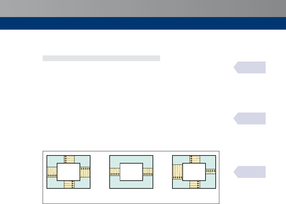
61
Torsion
9.3
Combined torsion and shear
Insolidsectionsthefollowingrelationshipshouldbesatisfied:
(
Ed
/
Rd,max
)+(
Ed
/
Rd,max
)≤1.0
where
Rd,max
=designtorsionalresistancemoment
= 2va
cw
cd
k
ef,i
sinycosyasinSection9.2.
Rd,max
=maximumdesignshearresistance
= a
cw
w
v
1
cd
(coty+cota)/(1+cot
2
y)asinSection7.3.2.
The effectsof torsionand shearfor both hollowand solidmembers maybe superimposed,
assumingthesamevalueforthestrutinclinationy.ThelimitsforygiveninSection7.3.2are
alsofullyapplicableforthecaseofcombinedshearandtorsion.
Forboxsections,eachwallshouldbeverifiedseparately,forthe combinationofshearforces
derivedfromshearandtorsion(Figure9.2).
a) Torsion
b) Shear
c) Combination
+ =
Figure 9.2
Internal actions combination within the different walls of a box section
BS EN 1992-2
Exp. (6.29)
BS EN 1992-2
6.3.2 (102)
BS EN 1992-2
fig. 6.104

62
10
10.1
10.1.1
10.1.2
Strut-and-tie models, bearing zones
and partially loaded areas
Design with strut-and-tie models
Struts
Thedesignstrengthforaconcretestrutinaregionwithtransversecompressivestressorno
transversestressmaybecalculatedfromthefollowingExpression(seeFigure10.1).
s
Rd,max
=
cd
=
0.85
ck
/
1.5
Figure 10.1
Design strength of concrete
struts without transverse
tension
s
Rd,max
s
Rd,max
Figure 10.2
Design strength of concrete
struts with transverse
tension
s
Rd,max
s
Rd,max
Thedesignstrengthforconcretestrutsshouldbereducedincrackedcompressionzonesand,
unlessamorerigorousapproachisused,maybecalculatedfromthefollowingExpression(see
Figure10.2).
s
Rd,max
=0.6
(1–
ck
/250)
cd
where
cd
=
1.0
ck
/
1.5
Ties
Reinforcementrequiredtoresisttheforcesattheconcentratednodesmaybesmearedovera
length(seeFigure10.3).Whenthereinforcementinthenodeareaextendsoveraconsiderable
length of an element, the reinforcement should be distributed over the length where the
compressiontrajectoriesarecurved(tiesandstruts).Thetensileforce,,maybeobtainedby:
Forpartialdiscontinuityregions( ≤/2)
=(–)/4
Forfulldiscontinuityregions( >/2)
=(1–0.7)/4
BS EN 1992-1-1
6.5.2
BS EN 1992-1-1
fig. 6.23
BS EN 1992-1-1
fig. 6.24
BS EN 1992-1-1
6.5.3

63
Strut-and-tiemodels,bearingzonesandpartiallyloadedareas
10.1.3
a) Partial discontinuity b) Full discontinuity
b
ef
b
ef
= 0.5H + 0.65a; aA h
a
b
z = h/2
h = H/2
F
F
h = b
Discontinuity
region
Continuity
region
Discontinuity
region
H
b
ef
b
ef
=
b
a
b
F
F
Figure 10.3
Parameters for the determination of transverse tensile forces in a compression field with smeared
reinforcement
Nodes
Therulesfornodesalsoapplytoregionswhereconcentratedforcesaretransferredinamember
andwhicharenotdesignedbythestrut-and-tiemethod.Theforcesactingatnodesshouldbe
inequilibrium.Transversetensileforcesperpendiculartoaninplanenodeshouldbeconsidered.
The dimensioning and detailing of concentrated nodes are critical in determining their
loadbearingresistance.Concentratednodesmaydevelop,forexample,wherepointloads are
applied, atsupports,inanchoragezoneswith concentrationofreinforcementor prestressing
tendons,atbendsinreinforcingbars,andatconnectionsandcornersofmembers.
Thedesignvaluesforthecompressivestresseswithinnodesmaybedeterminedinthreeways:
Incompressionnodeswherenotiesareanchoredatthenode(seeFigure10.4)
s
Rd,max
=
1.0
(1–
ck
/250)
cd
where
s
Rd,max
= maximumstresswhichcanbeappliedattheedgesofthenode
cd
=
0.85
ck
/
1.5
s
Rd,2
s
Rd,3
s
Rd,1
s
c,0
a
2
a
3
a
1
F
cd,1
= F
cd,1r
+ F
cd,l
F
cd,2
F
cd,3
F
cd,0
F
cd,1l
F
cd,1r
Figure 10.4
Compression node without ties
BS EN 1992-1-1
fig 6.25
BS EN 1992-1-1
6.5.4
BS EN 1992-1-1
fig. 6.26

64
Incompression–tensionnodeswithanchoredtiesprovidedinonedirection(seeFigure10.5)
s
Rd,max
=
0.85
(1–
ck
/250)
cd
where
s
Rd,max
isthemaximumofs
Rd,1
ands
Rd,2
cd
=
0.85
ck
/
1.5
s
Rd,1
s
Rd,2
s
0
s
u
s
0
F
td
a
1
l
bd
F
cd,1
F
cd,2
R 2s
0
a
2
Figure 10.5
Compression–tension node with reinforcement provided in one direction
Incompression–tensionnodeswithanchoredtiesprovidedinmorethanonedirection(see
Figure10.6),
s
Rd,max
=
0.75
(1–
ck
/250)
cd
where
cd
=
0.85
ck
/
1.5
s
Rd,max
F
td,1
F
td,2
F
cd
Figure 10.6
Compression–tension node with reinforcement provided in two directions
BS EN 1992-1-1
fig. 6.27
BS EN 1992-1-1
fig. 6.28

65
Strut-and-tiemodels,bearingzonesandpartiallyloadedareas
Theanchorageofthereinforcementincompression-tensionnodesstartsatthebeginningofthe
node;inthecaseofasupportanchorage,startingatitsinnerface(seeFigure10.5).Theanchorage
lengthshouldextendovertheentirenodelength.Incertaincases,thereinforcementmayalsobe
anchoredbehindthenode.
Partially loaded areas
Forauniformdistributionofloadonanarea
c0
(seeFigure10.7)theconcentratedresistance
forcemaybedeterminedasfollows:
Rdu
c0
cd
(
c1
c0
)
0.5
cd
c0
where
c0
= loadedarea,
c1
= maximumdesigndistributionareawithasimilarshapeto
c0
cd
=
0.85
ck
/
1.5
Thedesigndistributionarea
c1
requiredfortheresistanceforce
Rdu
shouldcorrespondtothe
followingconditions:
Theheightfortheloaddistributionintheloaddirectionshouldcorrespondtothe
conditionsgiveninFigure10.7.
Thecentreofthedesigndistributionarea
c1
shouldbeonthelineofactionpassing
throughthecentreoftheloadarea
c0
.
Ifthereismorethanonecompressionforceactingontheconcretecross-section,the
designeddistributionareasshouldnotoverlap.
Reinforcement should be provided to resist the tensile forces due to the effect of actions,
therulesforstrutandtiemaybeused.
Transversetensileforcescan arisein the localisedareanearaconcentratedloadandalso
from any further spread ofload outsidethe localised area.The strut-and-tie model used
should account for both of these potential sources of transverse tensile forces Further
guidanceandbackgroundaregivenbyHendy&Smith
[20]
.
Line of action
b
1
A
c1
A
c0
d
1
hR (b
2
– b
1
) and
b
2
A 3
b1
d
2
A 3d
1
R (d
2
– d
1
)
h
Figure 10.7
Design distribution for partially loaded areas
10.2
BS EN 1992-1-1
6.7
PD 6687-2
7.5
BS EN 1992-1-1
fig. 6.29

66
10.3
Bearing zones of bridges
Forbearingzonesofbridges,Section10.2forpartiallyloadedareasshouldbeused,noting
thefollowing.
ForconcreteclassesequaltoorhigherthanC55/67,theconcentratedresistanceforceshould
becalculatedusingthefollowingExpression:
Rdu
c0
cd
(0.46
ck
2/3
)(10.1
ck
)x(
c1
c0
)
0.5
3.0
c0
cd
(0.46
ck
)(10.1
ck
2/3
)
Thedistancefromtheedgeoftheloadedareatothefreeedgeoftheconcretesectionshould
notbelessthan1/6ofthecorrespondingdimensionoftheloadedareameasuredinthesame
direction.Innocaseshouldthedistancetothefreeedgebetakenaslessthan50mm.
Inordertoavoidedgesliding,uniformlydistributedreinforcementparalleltotheloadedfaceshould
beprovidedtothepointatwhichlocalcompressivestressesaredispersed.Thispointisdetermined
bydrawingalineatanangle,y(30°),tothedirectionofloadapplicationfromtheedgeofthesection
tointersectwiththeoppositeedgeoftheloadedsurface,asshowninFigure10.8.Thereinforcement
providedtoavoidedgeslidingshouldbeadequatelyanchored.
Figure 10.8
Edge sliding mechanism
F
Rdu
y
Thereinforcementprovidedinordertoavoidedgesliding(
r
)shouldbecalculatedinaccordance
withtheexpression
r
yd
≥
Rdu
/2.
BS EN 1992-2
fig. J.107
BS EN 1992-2
J.104.1 (103)
BS EN 1992-2
J.104.1 (102)
BS EN 1992-2
J.104.1 (104)

67
Prestressedmembersandstructures
Prestressed members and structures
General
Thesectionprovidesguidancethatisspecifictoprestressedconcreteusingstressedtendons.
Ingeneral,prestressisintroducedintheactioncombinationsdefinedinBSEN1990aspart
oftheloadingcasesanditseffectsshouldbeincludedintheappliedinternalmomentand
axialforce.
The contribution of the prestressing tendons to the resistance of the section should be
limited to theiradditional strength beyond prestressing.This requirementis most simply
achievedbytreatingthesecondaryeffectsofprestressasanappliedaction(i.e.aload),whilst
omittingtheprimaryeffectsofthedesignprestressingforce.Thismaybecalculatedassuming
thattheoriginofthestress–strainrelationshipofthetendonsisdisplacedbytheeffectsof
prestressing.
Brittle fracture
Brittlefailureofthemembercausedbyfailureofprestressingtendonsshouldbeavoidedby
using
oneofthreemethodsgivenbelow
.
Verification
Verifytheloadcapacityusingareducedareaofprestressasfollows:
Calculatetheappliedbendingmomentduetothefrequentcombinationofactions
freq
.
Determinethereducedareaofprestress,
p,Red
,thatresultsinthetensilestressreaching
ctm
attheextremetensionfibrewhenthesectionissubjecttothebendingmoment
calculatedabove.
p,Red
=(
freq
/–
ctm
)/[s
p
(1/
c
+/)]
where
= sectionmodulus
ctm
=meanvalueofconcretecylindercompressivestrength
s
p
=stressintendonsjustpriortocracking
c
= areaofconcrete
= eccentricityofthetendons
FurtherguidanceisgivenbyHendy&Smith
[20]
Usingthisreducedareaofprestress,calculatetheultimateflexuralcapacity.Itshouldbe
ensuredthatthisexceedsthebendingmomentduetothefrequentcombination.
Redistributionofinternalactionswithinthestructuremaybetakenintoaccountforthis
verificationandtheultimatebendingresistanceshouldbecalculatedusingthematerial
partialfactorsforaccidentaldesignsituationsgiveninTable2.9.
Assumingthereisnoconventionalreinforcementthen:
freq
≥(
ctm
s
)/[(
s
/)–[s
p
(1/
c
+/)/
p0.1k
]]
where
s
=leverarmfortheprestress,where
p,Red
hasbeenusedtodeterminethe
accidentalultimatelimitstate.
ctm
= meanvalueofconcretecylindercompressivestrength
s
p
=stressintendonsjustpriortocracking
11
11.1
11.2
11.2.1
BS EN 1992-2
6.1(109)

68
c
=areaofconcrete
=eccentricityofthetendons
FurtherguidanceisgivenbyHendy&Smith
[20]
Minimum provision
Theminimum reinforcementarea,
s,min
, isgivenbelow.Reinforcing steelprovidedfor other
purposesmaybeincludedin
s,min
.
s,min
=
rep
/(
s
yk
)
where
rep
= crackingbendingmomentcalculatedusinganappropriatetensilestrength,
ctk,0.05
attheextremetensionfibreofthesection,ignoringanyeffectof
prestressing.Atthejointofsegmentalprecastelements
rep
shouldbeassumed
tobezero
s
= leverarmattheultimatelimitstaterelatedtothereinforcingsteel
Thisminimumreinforcementsteelareashouldbeprovidedinregionswheretensilestressesoccur
intheconcreteunderthecharacteristiccombinationofactions.Inthischeckthesecondaryeffects
ofprestressingshouldbeconsideredandtheprimaryeffectsshouldbeignored.
Forpretensionedmembers,Expression(6.101a)shouldbeappliedusingoneofthealternative
approachesdescribedbelow:
Tendonswithconcretecoveratleast
1.0
timestheminimumspecifiedinFigure4.1are
consideredaseffectivein
s,min
.Avalueof
s
basedontheeffectivestrandsisusedinthe
expressionand
yk
isreplacedwith
p0.1k
.
Tendonssubjecttostresseslowerthan0.6
pk
afterlossesunderthecharacteristic
combinationofactionsareconsideredasfullyactive.Inthiscasethefollowingrequirement
shouldbemet.
s,min
yk
+
p
Ds
p
≥
rep
/
where
Ds
p
=smallerof0.4
ptk
and500MPa
Toensureadequateductilitytheminimumreinforcingsteelarea
s,min
,incontinuousbeams
shouldextendtotheintermediatesupportofthespanconsidered.Howeverthisextensionis
not necessary if, at the ultimate limit state, the resisting tensile capacity provided by
reinforcingandprestressingsteelabovethesupports, calculated with the characteristic
strength
yk
and
p0.1k
respectively, is less than the resisting compressive capacity of the
bottomflange.Thismeansthatthefailureofthecompressivezoneisnotlikelytooccur,and
canbeassessedasfollows:
s
yk
+
1.0
p
p0,1k
<
inf
0
1.0
ck
where
inf
= thethicknessofthebottomflangeofthesection.IncaseofT-sections,
inf
is
takenasequalto
0
0
= thewidthofthebottomflangeofthesection
s
= theareaofreinforcedsteelinthetensilezoneattheultimatelimitstate
p
= theareaofprestressingsteelinthetensilezoneattheultimatelimitstate
Inspection
Agreementofanappropriateinspectionregimewiththerelevantnationalauthorityonthebasis
ofsatisfactoryevidence.
11.2.2
11.2.3
BS EN 1992-2
Exp. (6.101a)
BS EN 1992-2
6.1(110)
BS EN 1992-2
Exp. (6.101b)
BS EN 1992-2
Exp. (6.102)

69
Prestressedmembersandstructures
Prestressing force during tensioning
Maximum stressing force
Theforceappliedtoatendon,
max
(i.e.theforceattheactiveendduringtensioning)
shallnotexceedthefollowingvalue:
max
=
p
s
p,max
where
p
= cross-sectionalareaofthetendon
s
p,max
= maximumstressappliedtothetendon
= MIN{
0.8
pk
;
0.9
p0,1k
}
Overstressingispermittediftheforceinthejackcanbemeasuredtoanaccuracyof±5%of
thefinalvalueoftheprestressingforce.Insuchcasesthemaximumprestressingforce
max
may
beincreasedto
0.95
p0.1k
p
(e.g.fortheoccurrenceofunexpectedlyhighfrictioninlong-line
pretensioning).
Forpre-tensioningthisrelaxationisintendedtobeusedonlywherethereare
unforeseenproblemsduringconstruction.
Theconcretecompressivestressinthestructureresultingfromtheprestressingforceandother
loadsactingatthetimeoftensioningorreleaseofprestress,shouldbelimitedto:
s
c
≤0.6
ck
()
where
ck
() = characteristiccompressivestrengthoftheconcreteattimewhenitissubjected
totheprestressingforce
Forpretensionedelementsthestressatthetimeoftransferofprestressmaybeincreasedto
0.7
ck
(),ifitcanbejustifiedbytestsorexperiencethatlongitudinalcrackingisprevented.
Ifthecompressivestresspermanentlyexceeds0.45
ck
()thenon-linearityofcreepshouldbe
takenintoaccount.
Prestress force
Thevalueoftheinitialprestressforce
m0
()(attime=
0
)appliedtotheconcreteimmediately
aftertensioningandanchoring(post-tensioning)oraftertransferofprestressing(pre-tensioning)
isobtainedbysubtractingfromtheforceattensioning
max
theimmediatelossesD
i
()and
shouldnotexceedthefollowingvalue:
m0
()=
p
s
pm0
()
where
s
pm0
() = stressinthetendonimmediatelyaftertensioningortransfer
= MIN{
0.75
pk
;
0.85
p0,1k
}
Atagiventimeanddistance(orarclength)fromtheactiveendofthetendonthemean
prestressforce
m,t
()isequaltothemaximumforce
max
imposedattheactiveend,minusthe
immediatelossesandthetimedependentlosses:
m,t
()=
m0
()-D
c+s+r
().
where
m,t
() = meanvalueoftheprestressforceatthetime>
0
andshouldbe
determinedwithrespecttotheprestressingmethod
D
c+s+r
() = changeinprestressduetotheresultofcreep,shrinkageoftheconcrete
andthelongtermrelaxationoftheprestressingsteel
Absolutevaluesareconsideredforallthelosses.
11.3
11.3.1
11.3.2
BS EN 1992-1-1
5.10.2.1
BS EN 1992-1-1
5.10.2.2(5)
BS EN 1992-1-1
5.10.3(2)
BS EN 1992-1-1
5.10.3(1)&(4)

70
Immediate losses
WhendeterminingtheimmediatelossesD
i
()thefollowingimmediateinfluencesshouldbe
consideredforpre-tensioningandpost-tensioningwhererelevant:
Lossesduetoelasticdeformationofconcrete,
D
el
.
Forpre-tensioning:
D
el
()=
p
p
s
c
()/
cm
()
where
p
= modulusofelasticityofprestressingsteel
cm
() = modulusofelasticityofconcreteattime,
s
c
() = stressintheconcreteadjacenttothetendonattransfer
Forpost-tensioning:
D
el
=
p
p
S(Ds
c
()/
cm
())
where
Ds
c
()=variationofstressintheconcreteatthecentreofgravityofthetendonsapplied
attime
=(–1)/2whenconsideringlossesbeforestressing.Asanapproximationmaybe
takenas1/2
=1forthevariationsduetopermanentactionsappliedafterprestressing
=numberofidenticaltendonssuccessivelyprestressed.
Lossesduetoshorttermrelaxation, D
r
(e.g.lossduetorelaxationoftheprestressing
duringtheperiodwhichelapsesbetweenthetensioningofthetendonsandprestressingof
theconcrete).
Lossesduetofriction,D
μ
(),inpost-tensionedtendonsmaybeestimatedfrom:
D
μ
()=
max
(1−e
–μ(y+kx)
)
where
y = sumoftheangulardisplacementsoveradistance(irrespectiveofdirectionorsign)
= coefficientoffrictionbetweenthetendonanditsduct
= unintentionalangulardisplacementforinternaltendons(perunitlength)
= distancealongthetendonfromthepointwheretheprestressingforceisequalto
max
(theforceattheactiveendduringtensioning)
ThevaluesandaregivenintherelevantEuropeanTechnicalApproval.Intheabsenceofdata
giveninaEuropeanTechnicalApprovalthevaluesforgiveninTable11.1maybeassumed.
Unintendedangulardisplacementsforinternaltendonswillgenerallybeintherange0.005<
<0.01permetre.
Table 11.1
Coefficients of friction, μ, for post-tensioned internal tendons and external unbonded tendons
Tendon type Internal
tendons
a
External unbonded tendons
Steel duct:
non-lubricated
HDPE duct:
non-lubricated
Steel duct:
lubricated
HDPE duct:
lubricated
Cold drawn wire
0.17 0.25 0.14 0.18 0.12
Strand
0.19 0.24 0.12 0.16 0.10
Deformed bar
0.65 – – – –
Smooth round bar
0.33 – – – –
Key
aFortendonswhichfillabouthalfoftheduct
11.3.3
BS EN 1992-1-1
5.10.3(3)
BS EN 1992-1-1
5.10.5.1(2)
BS EN 1992-1-1
5.10.5.2(1)
BS EN 1992-1-1
5.10.5.2(2)&(3)
BS EN 1992-1-1
table 5.1

71
Prestressedmembersandstructures
Lossesduetoanchorageslip, D
sl
,
whichareavailablefromtheEuropeanTechnical
Approval.
Lossesduetofrictionatthebends(inthecaseofcurvedwiresorstrands).
Time-dependent losses of prestress
Asimplifiedmethodtoevaluatetimedependentlossesatlocationxunderthe
permanentloadsisasfollows:
A
p
Ds
p,c+s+r
DP
c+s+r
== A
p
e
cs
E
p
+ 0.8Ds
pr
+
E
p
E
cm
h
(t,t
0
)s
c,QP
(1 +)
1 +
A
c
z
cp
I
c
E
p
A
p
E
cm
A
c
2
[1 + 0.8 h
(t,t
0
)]
where
p
= areaofalltheprestressingtendonsatthelocation
Ds
p,c+s+r
= absolutevalueofthevariationofstressinthetendonsduetocreep,
shrinkageandrelaxationatlocation,attime
e
cs
= estimatedshrinkagestrain,inabsolutevalue
p
= modulusofelasticityfortheprestressingsteel
cm
= modulusofelasticityfortheconcrete
Ds
pr
= absolutevalueofthevariationofstressinthetendonsatlocation,at
time,duetotherelaxationoftheprestressingsteel.Itisdeterminedfor
astressofs
p
=s
p
(+
m0
+c
2
),whichistheinitialstressinthetendons
duetoinitialprestressandquasi-permanentactions
h (
0
) = creepcoefficientatatimeandloadapplicationattime
0
s
c,QP
= stressintheconcreteadjacenttothetendons,duetoself-weightandinitial
prestressandotherquasi-permanentactionswhererelevant.Thevalueofs
c,QP
maybetheeffectofpartofself-weightandinitialprestressortheeffectofa
fullquasi-permanentcombinationofactions(s
c
(+
m0
+c
2
)),depending
onthestageofconstructionconsidered
c
= areaoftheconcretesection
c
= secondmomentofareaoftheconcretesection
cp
=distance between the centre of gravity of the concrete section and the
tendons
Compressivestressesand thecorrespondingstrainsshouldbeused withapositive sign.This
Expressionappliesforbondedtendonswhenlocalvaluesofstressesareusedandforunbonded
tendonswhenmeanvaluesofstressesareused.Themeanvaluesshouldbecalculatedbetween
straightsections limitedby the idealised deviation pointsfor external tendons or along the
entirelengthincaseofinternaltendons.
Effects of prestressing at ultimate limit state
Ingeneralthedesignvalueoftheprestressingforcemaybedeterminedfrom
d,t
()=g
P
,
m,t
()
For prestressed members with permanently unbonded tendons, it is generally necessary to
takethedeformationofthewholememberintoaccountwhencalculatingtheincreaseofthe
stressintheprestressingsteel.Ifnodetailedcalculationismade,itmaybeassumedthatthe
increaseofthe stressfromthe effective prestresstothe stress inthe ultimate limitstate is
100MPaunlessthetendonisoutwithb
d
fromthetensionface,inwhichcaseDs
p,ULS
=0.
b =0.1for≥1000mm
=0.25for≤500mm
Thevalueofbmaybeinterpolatedforthevaluesofbetween500mmand1000mm.
Ifthestressincreaseinexternaltendonsiscalculatedusingthedeformationstateof
theoverallmember,non-linearanalysisshouldbeused.
11.3.4
11.3.5
BS EN 1992-1-1
5.10.6
BS EN 1992-1-1
5.10.8 & NA
BS EN 1992-2
5.10.8 (103)

72
Fatigue
Verification conditions
Becauseofthehighliveloadtodeadloadratio,deckslabsarelikelytobeamongsttheelements
mostaffectedbyfatiguecalculations.However,testsshowthattheactualstressrangesinthe
reinforcementinthesearemuchlowerthantheconventionalelasticcalculationssuggest.Because
ofthis,theNAtoBSEN1992-2identifiescaseswherefatigueassessmentisnotrequiredand
providesconservativerules.
Afatigueverificationisgenerallynotnecessaryforthefollowingstructuresandstructuralelements:
Footbridges,withtheexceptionofstructuralcomponentsverysensitivetowindaction.
Buriedarchandframestructureswithaminimumearthcoverof1mand1.5mforroad
andrailwaybridges.
Foundations.
Piersandcolumnswhicharenotrigidlyconnectedtosuperstructures.
Retainingwallsofembankmentsforroadsandrailways.
Abutmentsofroadandrailwaybridgeswhicharenotrigidlyconnectedtosuperstructures,
excepttheslabsofhollowabutments.
Prestressingandreinforcingsteel,inregionswhere,underthefrequentloadcombinationof
actionsand
k
onlycompressivestressesoccurattheextremeconcretefibres.
Fatigue verification for road bridges is not necessary for the local effects of wheel loads
applieddirectlytoaslabspanningbetweenbeamsorwebsprovidedthat:
Theslabdoesnotcontainweldedreinforcementorreinforcementcouplers.
Theclearspantooveralldepthratiooftheslabdoesnotexceed18.
Theslabactscompositelywithitssupportingbeamsorwebs.
Either:
theslabalsoactscompositelywithtransversediaphragms;or
thewidthoftheslabperpendiculartoitsspanexceedsthreetimesitsclearspan.
Internal forces and stresses for fatigue verification
Thestresscalculationshallbebasedontheassumptionofcrackedcross-sectionsneglectingthe
tensilestrengthofconcretebutsatisfyingcompatibilityofstrains.
Theeffectofdifferentbondbehaviourofprestressingandreinforcingsteelshallbetakeninto
accountbyincreasingthestressrangeinthereinforcingsteelcalculatedundertheassumption
ofperfectbondbythefactor,n,givenby
A
s
+ A
p
A
s
+ A
p
n =
j
c
f
s
/f
p
m
where:
s
=areaofreinforcingsteel
p
=areaofprestressingtendonortendons
f
s
=largestdiameterofreinforcement
f
p
=diameterorequivalentdiameterofprestressingsteel
=1.6√
−
P
forbundles
=1.75f
wire
forsingle7-wirestrandswheref
wire
isthewirediameter
=1.20f
wire
forsingle3-wirestrandswheref
wire
isthewirediameter
j =ratioofbondstrengthbetweenbondedtendonsandribbedsteelinconcrete.The
valueissubjecttotherelevantEuropeanTechnicalApproval.Intheabsenceofthis
thevaluesgiveninTable12.1maybeused.
12
12.1
12.2
BS EN 1992-2
6.8.1(102)
BS EN 1992-2
NA 6.8.1(102)
BS EN 1992-1-1
6.8.2
PD 6687-2
7.6.1

73
Fatigue
Table 12.1
Ratio of bond strength,
j, between tendons and reinforcing steel
Prestressing steel
j
Pre-tensioned Bonded, post-tensioned
≤ C50/60 ≥ C70/85
Smooth bars and wires
Notapplicable 0.3 0.15
Strands
0.6 0.5 0.25
Indented wires
0.7 0.6 0.30
Ribbed bars
0.8 0.7 0.35
Note
ForintermediatevaluesbetweenC50/60andC70/85interpolationmaybeused.
Inthedesignoftheshearreinforcementtheinclinationofthecompressivestrutsy
fat
maybe
calculatedusingastrut-and-tiemodelorinaccordancewith
tan y
fat
= tan y ≤ 1.0
where
y = angleofcompressionstrutstothebeamaxisassumedinULSdesign(seeSection7.3.2).
Verification of concrete under compression or shear
S–Ncurvesrequiredtoundertakeafatigueverificationofconcreteundercompressionor
shearareunlikelytobeavailablefromNationalAuthorities.Intheabsenceofsuchdata,the
simplifiedapproachgiveninBSEN1992-2,AnnexNNmaybeusedforrailwaybridges,but
nosuchoptionexistsforhighwaybridges.
The fatigue verification for concrete under compression may be assumed
tobemet
if the
followingconditionissatisfied:
f
cd,fat
s
c,max
≤ 0.5 + 0.45
f
cd,fat
s
c,min
where
s
c,max
= maximum compressive stress at a fibre under the frequent load combination
(compressionmeasuredpositive)
s
c,min
= minimumcompressivestressatthesamefibrewheres
c,max
occurs.Ifs
c,min
isa
tensilestress,thens
c,min
shouldbetakenas0
cd,fat
= designfatiguestrengthofconcrete
ck
=
0.85
b
cc
(
0
)
cd
e1–
250
n
cd
=
1.0
ck
/
1.5
b
cc
(
0
)=coefficientforconcretestrengthatfirstloadapplication
=
b
cc
(t
0
) where = exp
s
1 –
28
t
0
0.5
where
0
= timeofthestartofthecyclicloadingonconcreteindays
= 0.2forcementofstrengthClassesCEM42.5R,CEM52.5NandCEM52.5R(ClassR)
= 0.25forcementofstrengthClassesCEM32.5R,CEM42.5(ClassN)
= 0.38forcementofstrengthClassCEM32.5(ClassS)
Themaximumvaluefortheratios
c,max
/
cd,fat
isgiveninTable12.2.
12.3
PD 6687-2
7.6.2
BS EN 1992-1-1
table 6.2
BS EN 1992-1-1
6.8.7(2)

74
Table 12.2
Values for
s
c,max
/f
cd, fat
Concrete strength s
c,max
/f
cd, fat
ck
≤50MPa ≤0.9
ck
>50MPa ≤0.8
Formembersnotrequiringdesignshearreinforcementfortheultimatelimitstateitmaybe
assumedthattheconcreteresistsfatigueduetosheareffectswherethefollowingapply:
for ≥ 0:
≤ 0.5 + 0.45
≤ 0.9 up to C50/60
≤ 0.8 greater than C55/67
V
Ed,min
V
Ed,max
V
Ed,max
V
Rd,c
V
Ed,min
V
Rd,c
for < 0:
≤ 0.5
V
Ed,min
V
Ed,max
V
Ed,max
V
Rd,c
V
Ed,min
V
Rd,c
where
Ed,max
=designvalueofthemaximumappliedshearforceunderfrequentload
combination
Ed,min
= isthedesignvalueoftheminimumappliedshearforceunderfrequentload
combinationinthecross-sectionwhere
Ed,max
occurs
Rd,c
= designvalueforshearresistanceaccordingtoSection7.2.1.
Limiting stress range for reinforcement under tension
Adequatefatigue resistancemaybe assumed for reinforcing bars under tension ifthestress
range under thefrequentcyclicload combinedwiththe basic combinationdoesnot exceed
70MPa
forunweldedbarsand
35MPa
forweldedbars.
For UK highway bridges, the values in Tables 12.3 and 12.4 may be used for straight
reinforcement.ThesearebasedonbarsconformingtoBS4449.Forbarsnotconformingto
BS4449,therulesforbars>16mmdiametershouldbeusedforallsizesunlesstheranges
forbars≤16mmdiametercanbejustified.
Table 12.3
Limiting stress ranges – longitudinal bending for unwelded reinforcing bars in road bridges, MPa
Span m Adjacent spans loaded Alternate spans loaded
Bars ≤ 16 mm Bars > 16 mm Bars ≤ 16 mm Bars > 16 mm
≤ 3.5
150 115 210 160
5
125 95 175 135
10
110 85 175 135
20
110 85 140 110
30 to 50
90 70 110 85
100
115 90 135 105
≥ 200
190 145 200 155
Notes
1Intermediatevaluesmaybeobtainedbylinearinterpolation.
2Thistableappliestoslabsbutneedonlybeappliedtothoseslabsthatdonotconformtothe
criteriagiveninSection12.1.
12.4
PD 6687-2
table 2A
BS EN 1992-1-1
6.8.7(4)
BS EN 1992-1-1
6.8.6(1)
PD 6687-2
7.6.3

75
Fatigue
Table 12.4
Limiting stress ranges – transverse bending for unwelded reinforcing bars in road bridges, MPa
Span m Bars ≤ 16 mm Bars > 16 mm
≤3.5
210 160
5
120 90
≥10
70 55
Notes
1Intermediatevaluesmaybeobtainedbylinearinterpolation.
2Thistableappliestoslabsbutneedonlybeappliedtothoseslabsthatdonotconformtothe
criteriagiveninSection12.1.
IfthestressrangelimitsexceedthevaluesgiveninTables12.3and12.4(e.g.forreinforcement
overthepier),fullfatiguechecksaretobecarriedoutusingthe‘damageequivalentstress
range’method,followingtheguidancegiveninAnnexNNofBSEN1992-2.Thestressranges
arecalculatedusing‘FatigueLoadModel3’,whichrepresentsafour-axlevehiclewithanall
upweightof48tonnes.AnnexNNfurtherincreasesthisweightto84tonnesforintermediate
supportsand67tonnesforotherareas.
PD 6687-2
table 2B

76
Serviceability
General
Thecommonserviceabilitylimitstatesconsideredare:
Stresslimitation.
Crackcontrol.
Deflectioncontrol.
Inthecalculationofstressesanddeflections,cross-sectionsshouldbeassumedtobeuncracked
providedthattheflexuraltensilestressdoesnotexceed
ct,eff
.Thevalueof
ct,eff
maybetaken
as
ctm
or
ctm,fl
providedthatthecalculationforminimumtensionreinforcementisalsobased
on the same value.For thepurposes of calculating crack widths and tension stiffening
ctm
shouldbeused.
Stress limitation
Longitudinalcracksmayoccurifthestresslevelunderthecharacteristiccombinationofloads
exceedsacriticalvalue.Suchcrackingmayleadtoareductionofdurability.Intheabsenceof
othermeasures,suchasanincreaseinthecovertoreinforcementinthecompressivezoneor
confinement by transverse reinforcement, it
isrecommendedthat
the compressive stress is
limitedtoavalue
0.6
ck
inareasexposedtoenvironmentsofexposureclassesXD,XFandXS
(seeTable4.2).Inthepresenceofconfinementthemaximumstresslimitis
0.66
ck
.
Ifthestressintheconcreteunderthequasi-permanentloadsislessthan
0.45
ck
,linearcreep
may be assumed. If the stress in concrete exceeds
0.45
ck
, non-linear creep should be
considered(seeSection3.1.2).
For the appearance unacceptable cracking or deformation may be assumed to be avoided
if,underthe characteristiccombinationofloads,thetensilestressinthereinforcementdoes
notexceed
0.8
yk
.Wherethestressiscausedbyanimposeddeformation,thetensilestress
should notexceed
1.0
yk
.The mean valueof the stress in prestressingtendons should not
exceed
0.75
pk
.
Crackcontrol(Section13.4)anddeflection(Section13.6) should alsobe
checked.
Calculation of crack widths
Thecrackwidth,
k
,maybecalculatedfromfollowingExpression:
k
=
r,max
(e
sm
–e
cm
)
where
r,max
= maximumcrackspacing
e
sm
= meanstraininthereinforcementundertherelevantcombinationofloads,
includingtheeffectofimposeddeformationsandtakingintoaccountthe
effectsoftensionstiffening.Onlytheadditionaltensilestrainbeyondthestate
ofzerostrainoftheconcreteatthesamelevelisconsidered
e
cm
= meanstrainintheconcretebetweencracks
e
sm
–e
cm
maybecalculatedfromtheExpression:
f
ct,eff
r
ct,eff
s
s
– k
t
E
s
(1 + a
e
r
p,eff
)
s
s
E
s
0.6
e
sm
– e
cm
=
where
s
s
= stressinthetensionreinforcementassumingacrackedsection.For
pretensionedmembers,s
s
maybereplacedbyDs
p
,whichisthestress
variationinprestressingtendonsfromthestateofzerostrainofthe
concreteatthesamelevel
13
13.1
13.2
13.3
BS EN 1992-1-1
7.1
BS EN 1992-2
7.2(102) & NA
PD 6687-2
8.1.1
PD 6687-2
8.1.2
BS EN 1992-1-1
7.3.4
BS EN 1992-1-1
7.2(3)
BS EN 1992-1-1
7.2(5), NA

77
Serviceability
t
= factordependentonthedurationoftheload
= 0.6forshorttermloading
= 0.4forlongtermloading
a
e
= ratio
s
/
cm
r
p,eff
= (
s
+j
1
2
p
')/
c,eff
where
p
' = areaofpre-orpost-tensionedtendonswithin
c,eff
.
c,eff
= effectiveareaofconcreteintensionsurroundingthereinforcementor
prestressingtendonsofdepth,
c,ef
,where
c,ef
isthelesserof
2.5(),()/3or/2(seeFigure13.3).
j
1
= adjustedratioofbondstrengthtakingintoaccountthedifferent
diametersofprestressingandreinforcingsteel:
= (j f
s
/f
p
)
0.5
j = ratioofbondstrengthofprestressingandreinforcingsteel,according
toTable12.1
Ifonlyprestressingsteelisusedtocontrolcracking,j
1
=j
0.5
f
s
= largestbardiameterofreinforcingsteel
f
p
= equivalentdiameteroftendonaccordingtoSection12.2
Insituationswherebondedreinforcementisfixedatreasonablyclosecentreswithinthetension
zone(spacing≤5(+f/2),themaximumfinalcrackspacingmaybecalculatedfromfollowing
Expression(seeFigure13.1):
r,max
=
3
1
2
4
f/r
p,eff
where
f = bar diameter.Wherea mixtureofbardiametersisusedinasection,anequivalent
diameter,f
eq
,shouldbeused
where
f
eq
= (
1
f
1
2
+
2
f
2
)/(
1
f
1
+
2
f
2
)
1
= numberofbarsofdiameterf
1
2
= numberofbarsofdiameterf
2
3
=
3.4
= covertothelongitudinalreinforcement.
Thenominalcover,
nom
,maybeused.
1
= coefficientwhichtakesaccountofthebondpropertiesofthebonded
reinforcement
= 0.8forhighbondbars
= 1.6forbarswithaneffectivelyplainsurface(e.g.prestressingtendons)
f
Concrete
tension surface
Crack spacing predicted
by Expression (7.14)
Crack spacing
predicted by
Expression (7.11)
Actual
crack width
Neutral axis
(h – x)
5(c + f/2)
c
w
Figure 13.1
Crack width, w, at concrete surface relative to distance from bar
BS EN 1992-1-1
fig. 7.2
BS EN 1992-1-1
Exp. (7.11)

78
4
=
0.425
2
= coefficientwhichtakesaccountofthedistributionofstrain
= 0.5forbending
= 1.0forpuretension
Forcasesofeccentrictensionorforlocalareas,intermediatevaluesof
2
should
beusedwhichmaybecalculatedfromtherelation:
2
= (e
1
+e
2
)/(2e
1
)
e
1
= greatertensilestrainattheboundariesofthesectionconsidered,assessedon
thebasisofacrackedsection
e
2
= lessertensilestrainattheboundariesofthesectionconsidered,assessedonthe
basisofacrackedsection
Wherethespacingofthebondedreinforcementexceeds5(c+f/2)(seeFigure13.1)orwhere
thereisnobondedreinforcementwithinthetensionzone,anupperboundtothecrackwidth
maybefoundbyassumingamaximumcrackspacing:
r,max
=1.3()
Wheretheanglebetweentheaxesofprincipalstressandthedirectionofthereinforcement,for
membersreinforcedintwoorthogonaldirections,issignificant(>15°),thenthecrackspacing
r,max
maybecalculatedfromthefollowingexpression:
r,max
=1/(cosy/
r,max,y
+siny/
r,max,z
)
where
y = anglebetweenthereinforcementinthedirectionandthedirectionofthe
principaltensilestress
r,max,y
= crackspacingcalculatedinthey-direction
r,max,z
= crackspacingcalculatedinthez-direction
Alimitingcalculatedcrackwidth
max
,takingaccountoftheproposedfunctionandnatureof
thestructureandthecostsoflimitingcracking,shouldbeestablished.Duetotherandomnature
ofthecrackingphenomenon,actualcrackwidthscannot be predicted.However,ifthecrack
widths calculated inaccordancewith the modelsgivenin BS EN 1992-2arelimited to the
valuesgiveninTable13.1,theperformanceofthestructureisunlikelytobeimpaired.
The decompression limit requires that all concrete within a certain distance of bonded
tendons or their ducts should remain in compression under the specified loading. The
distancewithinwhichallconcreteshouldremainincompressionshouldbetakenasthevalue
of
min,dur
.WherethemosttensilefaceofasectionisnotsubjecttoXDorXSexposurebut
another face is, the decompressionlimit shouldrequire all tendons within 100 mm of a
surfacesubjecttoXDorXSexposuretohaveadepth
min,dur
ofconcretein compression
betweenthemandsurfacessubjecttoXDorXSexposure.
Sincethedecompressionlimitof100mmislikelytobegreaterthanthecoverrequiredfor
durability,thisintroducesananomaly.Forexample,only50mmofconcreteincompression
might be deemed adequate to protect the tendons, whereas 60 mm of concrete in
compressionplus40mmnotincompressionwouldnot,whichisclearlyillogical.Changing
thedistancefromtherecommendedvalueof100mmtothecoverrequiredfordurability,
min,dur,
ismorelogical.
In some situations, such as structures cast against the ground,
nom
will be significantly
greaterthanthecoverrequiredfordurability.Wheretherearenoappearancerequirements
itisreasonabletodeterminethecrackwidthatthecoverrequiredfordurabilityandverify
thatitdoesnotexceedtherelevantmaximumcrackwidth.Thismaybedonebymultiplying
thecrackwidthdeterminedatthesurfaceby(
min,dur,
+D
dev
)/
nom
togivethecrackwidth
at the cover required for durability, and verifying that it is not greater than
max
. This
approach assumes that the crack width varies linearly from zero at the bar. Given the
accuracyofcrackcalculationmethodsthissimplificationisconsideredreasonable.
BS EN 1992-2
NA. NA.2.2
BS EN 1992-2
7.3.1(105) & NA
BS EN 1992-1-1
Exp. (7.14)
PD 6687-2
8.2.1b)
PD 6687-2
8.2.2

79
Serviceability
13.4
Table 13.1
Recommended values of w
max
and relevant combination rules
Exposure class
a
Reinforced members and
prestressed members without
bonded tendons
Prestressed members with bonded
tendons
Quasi-permanent load
combination
b
(mm)
Frequent load combination
b
(mm)
X0, XC1
0.3
c
0.2
XC2, XC3, XC4
0.3
0.2
d
XD1, XD2, XD3
XS1, XS2, XS3
0.3
0.2
e
anddecompression
Key
a
Theexposureclassconsidered,includingattransfer,appliestothemostsevereexposurethesurface
willbesubjecttoinservice.
b
Forthecrackwidthchecksundercombinationswhichincludetemperaturedistribution,theresulting
memberforcesshouldbecalculatedusinggrosssectionconcretepropertiesandself-equilibrating
thermalstresseswithinasectionmaybeignored.
cForX0,XC1exposureclasses,crackwidthhasnoinfluenceondurabilityandthislimitissetto
guaranteeacceptableappearance.Intheabsenceofappearanceconditionsthislimitmayberelaxed.
dFortheseexposureclasses,inaddition,decompressionshouldbecheckedunderthequasipermanent
combinationofloads.
e
0.2appliestothepartsofthememberthatdonothavetobecheckedfordecompression.
Control of cracking
WheretheminimumreinforcementgivenbySection13.5isprovided,crackwidthsareunlikely
tobeexcessiveif:
Forcrackingcausedpredominantlybyrestraint,thebarsizesgiveninTable13.2arenot
exceededwherethesteelstressisthevalueobtainedimmediatelyaftercracking(i.e.s
s
in
Section13.5).
Forcrackscausedmainlybyloading,eithertheprovisionsofTable13.2ortheprovisionsof
Table13.3arecompliedwith.Thesteelstressshouldbecalculatedonthebasisofacracked
sectionundertherelevantcombinationofactions.
Forpre-tensionedconcrete,wherecrackcontrolismainlyprovidedbytendonswithdirectbond,
Tables13.2and13.3maybeusedwithastressequaltothetotalstressminusprestress.For
post-tensionedconcrete,wherecrackcontrolisprovidedmainlybyordinaryreinforcement,the
tablesmaybeusedwiththestressinthisreinforcementcalculatedwiththeeffectofprestressing
forcesincluded.
Themaximumbardiametershouldbemodifiedasfollows:
Bending(atleastpartofsectionincompression):
f
s
= f*
s
(f
ct,eff
/2.9)
k
c
h
cr
2 (h – d)
Tension(uniformaxialtension):
f
s
= f*
s
(f
ct,eff
/2.9) h
cr
/(8(h – d))
where
f
s
= adjustedmaximumbardiameter
f
s
= maximumbarsizegivenintheTable13.2
= overalldepthofthesection
cr
= depthofthetensilezoneimmediatelypriortocracking,consideringthe
characteristicvaluesofprestressandaxialforcesunderthequasi-permanent
combinationofactions
= effectivedepthtothecentroidoftheouterlayerofreinforcement
BS EN 1992-2 &
NA, table NA.2
BS EN 1992-1-1
7.3.3(2)

80
Whereallthesectionisundertension–istheminimumdistancefromthecentroidofthe
layerof reinforcementto the face ofthe concrete(consider eachface wherethe bar is not
placedsymmetrically).
Table 13.2
Maximum bar diameters for crack control
Steel stress (MPa) Maximum bar size (mm) for crack widths of
0.4 mm 0.3 mm 0.2 mm
160 40 32 25
200 32 25 16
240 20 16 12
280 16 12 8
320 12 10 6
360 10 8 5
400 8 6 4
450 6 5 —
Table 13.3
Maximum bar spacing for crack control
Steel stress (MPa) Maximum bar spacing (mm) for maximum crack widths of
0.4 mm 0.3 mm 0.2 mm
160 300 300 200
200 300 250 150
240 250 200 100
280 200 150 50
320 150 100 —
360 100 50 —
Minimum reinforcement areas of main bars
Ifcrackcontrolisrequired,aminimumamountofbondedreinforcementisrequiredtocontrol
crackinginareaswheretensionisexpected.Therequiredminimumareasofreinforcement
s,min
maybecalculatedasfollows.Inprofiledcross-sectionslikeT-beamsandboxgirders,minimum
reinforcementshouldbedeterminedfortheindividualpartsofthesection(webs,flanges).
s,min
=
c
ct,eff
ct
/s
s
where
ct
= areaofconcretewithintensilezone.Thetensilezoneisthatpartofthesection
whichiscalculatedtobeintensionjustbeforeformationofthefirstcrack
s
s
= absolutevalueofthemaximumstresspermittedinthereinforcement
immediatelyafterformationofthecrack.Thismaybetakenastheyieldstrength
ofthereinforcement,
yk
.Alowervaluemay,however,beneededtosatisfythe
crackwidthlimitsaccordingtothemaximumbarsizeorspacingindicatedin
Tables13.2and13.3.
ct,eff
= meanvalueofthetensilestrengthoftheconcreteeffectiveatthetimewhenthe
cracksmayfirstbeexpectedtooccur.
=
ctm
orlower(
ctm
())ifcrackingisexpectedearlierthan28days
Aminimumvalueof2.9MPashouldbetaken
= coefficientwhichallowsfortheeffectofnon-uniformself-equilibratingstresses,
whichleadtoareductionofrestraintforces
= 1.0forwebswith≤300mmorflangeswithwidthslessthan300mm,
intermediatevaluesmaybeinterpolated
13.5
BS EN 1992-1-1
table 7.3N
BS EN 1992-1-1
7.3.2(1)
BS EN 1992-2
7.3.2(102)
BS EN 1992-1-1
table 7.2N
BS EN 1992-1-1
Exp. (7.1)
BS EN 1992-2
7.3.2(105)

81
Serviceability
= 0.65forwebswith≥800mmorflangeswithwidthsgreaterthan800mm,
intermediatevaluesmaybeinterpolated
c
= coefficientwhichtakesaccountofthestressdistributionwithinthesection
immediatelypriortocrackingandofthechangeoftheleverarm:
= 1.0forpuretension.
= 0.4forpurebending.
= 0.4[1–(s
c
/(
1
(/*)
ct,eff
))]≤1forrectangularsectionsandwebsofbox
sectionsandT-sections.
= 0.9
cr
/(
ct
ct,eff
)≥0.5forflangesofboxsectionsandT-sections.
s
c
= meanstressoftheconcreteactingonthepartofthesectionunderconsideration.
=
Ed
/
Ed
= axialforceattheserviceabilitylimitstateactingonthepartofthecross-section
underconsideration(compressiveforcepositive).
Ed
shouldbedetermined
consideringthecharacteristicvaluesofprestressandaxialforcesunderthe
relevantcombinationofactions
* = MIN{;1.0}
1
= coefficientconsideringtheeffectsofaxialforcesonthestressdistribution:
= 1.5if
Ed
isacompressiveforce
= */if
Ed
isatensileforce
cr
= absolutevalueofthetensileforcewithintheflangeimmediatelypriortocracking
duetothecrackingmomentcalculatedwith
ct,eff
SeealsoSection15.2.1forasimplifiedmethodofcalculatingminimumareaofsteel.
Inflangedcross-sectionslikeT-beamsandboxgirders,thedivisionintopartsshouldbeasindicated
inFigure13.2.
s
c, web
s
c, flange
f
ct,eff
f
ct,eff
Flange Flange
Web
S
flange
S
m
S
web
Web Flange
a) Components b) Stresses
Figure 13.2
Example for a division of a flanged cross-section for analysis of cracking
Bondedtendonsinthetensionzonemaybeassumedtocontributetocrackcontrolwithina
distance≤150mmfromthecentreofthetendon.Thismaybetakenintoaccountbyincluding
thetermj
1
p
'
D
p
intheExpressionabovetogive:
s,min
=(
c
ct,eff
ct
–j
1
p
'
Ds
p
)/s
s
where
p
'
= areaofpre-orpost-tensionedtendonswithin
c,eff
c,eff
= effectiveareaofconcreteintensionsurroundingthereinforcementor
prestressingtendonsofdepth,
c,ef
c,ef
= MIN{2.5();()/3;/2}(seeFigure13.3)
j
1
= adjustedratioofbondstrengthtakingintoaccountthedifferentdiametersof
prestressingandreinforcingsteel
=(j f
s
/f
p
)
0.5
= j
0.5
ifonlyprestressingsteelisusedtocontrolcracking
j = ratioofbondstrengthofprestressingandreinforcingsteel,accordingto
Table13.4
BS EN 1992-2
fig. 7.101
BS EN 1992-1-1
7.3.2(3)

82
f
s
= largestbardiameterofreinforcingsteel
f
p
= equivalentdiameteroftendon
= 1.6
p
0.5
forbundles
= 1.75f
wire
forsingle7wirestrandswheref
wire
isthewirediameter
= 1.20f
wire
forsingle3wirestrandswheref
wire
isthewirediameter
Ds
p
= stressvariationinprestressingtendonsfromthestateofzerostrainofthe
concreteatthesamelevel
Level of steel centroid
Effective tension area, A
c,eff
Effective tension area, A
c,eff
Effective tension area for upper surface, A
ct,eff
Effective tension area for lower surface, A
cb,eff
e
2
= 0
e
2
= 0
a) Beam
b) Slab
c) Member in tension
e
1
e
1
e
2
e
1
h
c,ef
h
c,ef
h
c,ef
h
c,ef
h
h
d
h
d
d
x
d
x
Figure 13.3
Effective tension area (typical cases)
Inprestressedmembersnominimumreinforcementisrequiredinsectionswhere,underthe
characteristiccombination of loads and the characteristic valueof prestress, the concreteis
compressedortheabsolutevalueofthetensilestressintheconcreteisbelow
ct,eff
.
Table 13.4
Ratio of bond strength, j , between tendons and reinforcing steel
Prestressing steel
j
Pre-tensioned Bonded, post-tensioned
≤ C50/60 ≥ C70/85
Smooth bars and wires
Notapplicable 0.3 0.15
Strands
0.6 0.5 0.25
Indented wires
0.7 0.6 0.30
Ribbed bars
0.8 0.7 0.35
Note
ForintermediatevaluesbetweenC50/60andC70/85interpolationmaybeused.
BS EN 1992-1-1
Fig 7.1
BS EN 1992-1-1
7.3.2 (4)
BS EN 1992-1-1
table 6.2

83
Serviceability
Control of deflection
The calculation method adopted shall represent the true behaviour of the structure under
relevantactionstoanaccuracyappropriatetotheobjectivesofthecalculation.
Memberswhicharenotexpectedtobeloadedabovethelevelwhichwouldcausethetensile
strengthoftheconcretetobeexceededanywherewithinthemembershouldbeconsideredto
beuncracked.Memberswhichareexpectedtocrack,butmaynotbefullycracked,willbehave
inamannerintermediatebetweentheuncrackedandfullycrackedconditionsand,formembers
subjected mainly to flexure, an adequate prediction of behaviour is given in the following
expression:
az a
II
(1za
I
where
a deformationparameterconsideredwhichmaybe,forexample,astrain,a
curvature,orarotation.(Asasimplification,amayalsobetakenasadeflection
–seebelow)
a
I
a
II
thevaluesoftheparametercalculatedfortheuncrackedandfullycracked
conditionsrespectively
z distributioncoefficient(allowingfortensioningstiffeningatasection)
1–b(s
sr
/s
s
)
2
0foruncrackedsections
b coefficienttakingaccountoftheinfluenceofthedurationoftheloadingorof
repeatedloadingontheaveragestrain
1.0forasingleshort-termloading
0.5forsustainedloadsormanycyclesofrepeatedloading
s
s
stressinthetensionreinforcementcalculatedonthebasisofacrackedsection
s
sr
stressinthetensionreinforcementcalculatedonthebasisofacrackedsection
undertheloadingconditionscausingfirstcracking
Note:s
sr
s
s
maybereplacedby
cr
/forflexureor
cr
/forpuretension,where
cr
isthe
crackingmomentand
cr
isthecrackingforce.
Deformations due to loading may be assessed using the tensile strength and the effective
modulusofelasticityoftheconcrete.
Table3.1indicatestherangeoflikelyvaluesfortensilestrength.Ingeneral,thebestestimateof
thebehaviourwillbeobtainedif
ctm
isused.Whereitcanbeshownthattherearenoaxial
tensilestresses(e.g.thosecausedbyshrinkageorthermaleffects)theflexuraltensilestrength,
ctm,fl
,maybeused.
ctm,fl
MAX{(1.6–/1000)
ctm
;
ctm
}
where
= totalmemberdepthinmm
ctm
= meanaxialtensilestrengthfromTable3.1
Forloadswithadurationcausingcreep,thetotaldeformationincludingcreepmaybecalculated
byusinganeffectivemodulusofelasticityforconcreteaccordingtothefollowingExpression
c,eff
cm
1h(∞
0
))
where
h(∞
0
)=creepcoefficientrelevantfortheloadandtimeinterval(seeSection3.1.2)
Shrinkagecurvaturesmaybeassessedfromthefollowing:
1/
cs
=e
as
a
e
/
where
1/
cs
= curvatureduetoshrinkage
13.6
BS EN 1992-1-1
7.4.3(2)
BS EN 1992-1-1
7.4.3(3)
BS EN 1992-1-1
Exp. (7.18)
BS EN 1992-1-1
7.4.3(4)
BS EN 1992-1-1
3.1.8
BS EN 1992-1-1
7.4.3(5)
BS EN 1992-1-1
7.4.3(6)

84
e
cs
= freeshrinkagestrain(seeSection3.1.3)
= firstmomentofareaofthereinforcementaboutthecentroidofthesection
= secondmomentofareaofthesection
a
e
= effectivemodularratio
=
s
/
c,eff
andshouldbecalculatedfortheuncrackedconditionandthefullycrackedcondition,the
finalcurvaturebeingassessedusingtheExpressionforaabove.
Themostrigorousmethodofassessingdeflectionsusingthemethodgivenaboveistocompute
the curvatures at frequent sections alongthe memberand then calculate the deflection by
numerical integration. In mostcases it will be acceptable to computethe deflection twice,
assumingthewholemembertobeintheuncrackedandfullycrackedconditioninturn,and
theninterpolateusingtheExpressionforaabove.
BS EN 1992-1-1
7.4.3(7)

85
Detailing–generalrequirements
Detailing – general requirements
General
Therules givenin this sectionapplyto ribbedreinforcement,welded mesh andprestressing
tendonsusedinstructuressubjectpredominantlytostaticloading.
Unlessotherwisestated,therulesforindividualbarsalsoapplyforbundlesofbarsforwhich
anequivalentdiameterf
n
=f(
b
)
0.5
shouldbeusedinthecalculations.InthisExpression,
b
isthenumberofbarsinthebundle.Avaluefor
b
shouldbelimitedtofourverticalbarsin
compressionandinlappedjoints,andtothreeinallothercases.Thevalueoff
n
shouldbe
lessthanorequalto55mm.
Thecleardistancebetween(andthecoverto)bundledbarsshouldbemeasuredfromthe
actualexternalcontourofthebundledbars.Barsareallowedtotouchoneanotheratlaps
andtheyneednotbetreatedasbundledbarsundertheseconditions.
Spacing of bars
Thespacingofbarsshouldbesuchthatconcretecanbeplacedandcompactedsatisfactorilyfor
thedevelopmentofbond.
Thecleardistancebetweenindividualparallelbarsorbetweenhorizontallayersofparallelbarsshould
notbelessthanthe
bardiameter,
theaggregatesize+
5mm,
or20mm,whicheveristhegreatest.
Wherebarsarepositionedinseparatehorizontallayers,thebarsineachlayershouldbelocated
verticallyaboveeachother.Thereshouldbesufficientspacebetweentheresultingcolumnsof
barstoallowaccessforvibratorstogivegoodcompactionoftheconcrete.
Mandrel sizes for bent bars
Thediametertowhichabarisbentshouldbesuchastoavoiddamagetothereinforcement
andcrushingofconcreteinsidethebendofthebar.Toavoiddamagetoreinforcementthe
mandrelsizeisasfollows:
4f,
forbardiameterf≤16mm
7f,
forbardiameterf>16mm
20f,
formeshbentafterweldingwheretransversebarisonorwithin4fofthebend.
Otherwise
4f,
or
7f,
asabove.WeldingmustcomplywithISO/FDIS17660-2
[
22
]
.
Themandreldiameterf
m
toavoidcrushingofconcreteinsidethebendneednotbecheckedif:
Anchorageofthebardoesnotrequirealengthmorethan5 fpasttheendofthebend;and
Thebarisnotpositionedatanedgeandthereisacrossbar(ofdiameter≥ f)insidethebend,and
Diametersnotedaboveareused.
Otherwisethefollowingminimummandreldiameterf
m,min
shouldbeused:
f
m,min
≥
bt
((1/
b
)+1/(2f))/
cd
where
bt
= tensileforceinthebaratthestartofthebendcausedbyultimateloads
b
= halfthecentretocentrespacingofbars(perpendiculartotheplaneofthe
bend).Forbarsadjacenttothefaceofthemember,
b
=cover+0.5f
cd
=
0.85
ck
/
1.5
Thevalueof
cd
shouldnotbetakengreaterthanthatforconcreteclassC55/67
where
ck
= characteristiccylinderstrength
14
14.1
14.2
14.3
BS EN 1992-1-1
8.1(1)
BS EN 1992-1-1
8.9.1(1) & (2)
BS EN 1992-1-1
8.9.1(3) & (4)
BS EN 1992-1-1
8.2
BS EN 1992-1-1
8.3(1) & (2)
BS EN 1992-1-1
table 8.1N & NA
BS EN 1992-1-1
8.3(3)
BS EN 1992-1-1
Exp. (8.1)
BS EN 1992-1-1
3.1.6(1) & NA to
BS EN 1992-2

86
Anchorage of bars
General
Allreinforcementshouldbesoanchoredthattheforcesinthemaresafelytransmittedtothe
surroundingconcretebybondwithoutcausingcracksorspalling.Thecommonmethodsof
anchorageoflongitudinalbarsandlinksareshowninFigures14.1and14.2.
a) Basic anchorage length l
b,rqd
, for any
shape measured along the centreline
b,rqd
f
bd
b) Equivalent anchorage length for
standard bend 90º a < 150º
where l
b,eq
= a
1
l
b,rqd
b,eq
≥5f
a
e) Welded transverse bar
where l
b,eq
= a
4
l
b,rqd
b,eq
≥5f
f
≥0.6f
c) Equivalent anchorage length for
standard hook
where l
b,eq
= a
1
l
b,rqd
b,eq
≥150º
≥5
f
d) Equivalent anchorage length for
standard loop
where l
b,eq
= a
1
l
b,rqd
b,eq
Key
bd
= designanchoragelength
b,req
= basicanchoragelength
b,eq
= equivalentanchoragelength
Figure 14.1
Methods of anchorage other than by a straight bar
c) Two welded
transverse bars
d) Single welded
transverse bar
ff ff
5f,but
≥50mm
10
f,but
≥70mm
≥0.7
f
≥2f
≥1.4f
≥10mm
≥10mm
≥20mm
≤50mm
Figure 14.2
Anchorage of links
14.4
14.4.1
BS EN 1992-1-1
8.4(1) & (2)
BS EN 1992-1-1
fig. 8.1
BS EN 1992-1-1
fig. 8.5

87
Detailing–generalrequirements
Design anchorage length l
bd
Thedesignanchoragelength
bd
is
bd
=(a
1
a
2
a
3
a
4
a
5
)
b,rqd
≥
b,min
where
a
1
= factordealingwiththeformofbarassumingadequatecover
=0.7forbentbarsintensionwhere
d
>3f,where
d
isdefinedinFigure14.3
=1.0otherwiseforbarsintension
=1.0forbarsincompression
a
2
= factordealingwitheffectofconcreteminimumcover
=1–0.15(
d
–f)/f≥0.7forstraightbarsintensionbut≤1.0
=1–0.15(
d
–3f)/f≥0.7forbentbarsintensionbut≤1.0
=1.0otherwiseforbarsintension
=1.0forbarsincompression
a
3
= factordealingwitheffectofconfinementbytransversereinforcement
=1.0generally
a
4
= factordealingwiththeeffectofinfluenceofweldedtransversebars
=0.7foraweldedtransversebarconformingwithFigure14.1e)
=1.0otherwise
a
5
= factordealingwiththeeffectofpressuretransversetotheplaneofsplitting
alongthedesignanchoragelength
=1.0generally
b,rqd
= basicanchoragelength(seeSection14.4.3)
b,min
= theminimumanchoragelength
≥ MAX{0.3
b,rqd
;10f;100mm}intensionbars;and
≥ MAX{0.6
b,rqd
;10f;100mm}incompressionbars.
Theproduct(a
2
a
3
a
5
)≥ 0.7
Figure 14.3
Values of
c
d
for beams
and slabs
a) Straight bars
c
d
= minimum of a/2, c or c
1
b) Bent or hooked bars
c
d
= minimum of a/2 or c
1
1
1
Note
and
1
aretakentobenominalcovers
Basic anchorage length l
b,rqd
b,rqd
=basicanchoragelengthrequired=(f/4)(s
sd
/
bd
)
where
f = diameterofthebar
s
sd
= designstressinthebaratthepositionfromwheretheanchorageismeasured
bd
= ultimatebondstress(seeSection14.5)
Theanchoragelengthshouldbemeasuredalongthecentrelineofthebarinbentbars.
14.4.2
14.4.3
BS EN 1992-1-1
8.4.4(1) & table 8.2
BS EN 1992-1-1
fig. 8.3
BS EN 1992-1-1
8.4.3

88
Equivalent anchorage length l
b,eq
Asasimplification
FortheshapesshowninFigure14.1b)tod)anequivalentanchoragelength
b,eq
maybe
usedwhere
b,eq
=a
1
b,rqd
.
ForthearrangementshowninFigure14.1e)
b,eq
=a
4
b,req
.
Ultimate bond stress
Theultimatebondstress,
bd
,forribbedbarsmaybetakenas(seealsoTable14.1)
bd
=2.25n
1
n
2
ctd
where
n
1
= coefficientrelatedtothequalityofthebondconditionandthepositionofthebar
duringconcreting
= 1.0for‘good’bondconditions(seeFigure14.4fordefinition)
= 0.7forallothercasesandforbarsinstructuralelementsbuiltusingslipforms
n
2
= coefficientrelatedtobardiameter
= 1.0forbardiameter≤32mm
= (132–f)/100forbardiameter>32mm
ctd
= (a
ct
ctk,0.05
/g
C
)isthedesignvalueoftensilestrengthusingthevalueof
ctk,0.05
obtainedfromTable3.1,a
ct
=
1.0
andg
C
=
1.5
.
Duetothebrittlenessofhigher
strengthconcrete
ctk,0.05
shouldbelimitedheretothevalueforC60/75,unlessit
canbeverifiedthattheaveragebondstrengthincreasesabovethislimit
Directionofconcreting
Directionofconcreting
Directionofconcreting
Directionofconcreting
Key
b) h 250 mm d) h > 600 mm
300
c)
h > 250 mm
250
a) 45º
a 90º
a
‘good’bondconditions
‘poor’bondconditions
Figure 14.4
Description of bond conditions
14.4.4
14.5
BS EN 1992-1-1
8.4.4(2)
BS EN 1992-1-1
8.4.2(2)
BS EN 1992-2
3.1.6(102) & NA
BS EN 1992-1-1
fig. 8.2

89
Detailing–generalrequirements
Table 14.1
Design bond stress for different bond conditions
Design bond stress f
bd
(N/mm
2
)
C25/30 C30/37 C35/45 C40/50 C45/55 C50/60 C55/67 C60/75
Good bond &
f ≤ 32 mm
2.7 3.0 3.3 3.8 4.1 4.4 4.5 4.7
Good bond &
f = 40 mm
2.5 2.8 3.0 3.5 3.7 4.0 4.1 4.3
Poor bond &
f ≤ 32 mm
1.9 2.1 2.3 2.6 2.8 3.0 3.2 3.3
Poor bond &
f = 40 mm
1.7 1.9 2.1 2.4 2.6 2.8 2.9 3.0
Anchorage of tendons at ULS
The anchorage of tendons should be checked in sections where the concrete tensile stress
exceeds
ctk,0.05
(
ctk,0.05
should not exceed the value for classC60/75 concrete).The total
anchoragelengthforatendonwithastresss
pd
is:
bpd
=
pt2
+(a
2
f(s
pd
–s
pm
,
∞
)/
bpd
)
where
pt2
=1.2(a
1
a
2
fs
pm,0
/
bpt
)
where
a
1
= 1.0forgradualreleaseofprestressand1.25forsuddenrelease
s
pm,0
= stressinthetendonjustafterrelease
bpt
= n
p1
n
1
ctd
()
n
p1
= 2.7forindentedwiresand3.2for3-and7-wirestrands
n
1
= 1.0forgoodbondconditionsand0.7otherwise
ctd
() = designtensilevalueofstrengthatthetimeofrelease
=
1.0
0.7
ctm
()/
1.5
ctm
() = (b
cc
())
a
ctm
b
cc
() = coefficientwhichdependsontheageofloading
=
exp
{
s
[
1–(
0.5
]}
28
t
)
= coefficientwhichdependsontypeofcement(seeSection3.1.2)
= 0.20forcementstrengthclassesCEM42.5R,CEM52.5NandCEM52.5R(ClassR)
= 0.25forcementstrengthclassesCEM32.5R,CEM42.5N(ClassN)
= 0.38forcementstrengthclassCEM32.5(ClassS)
= ageofconcreteindays
ctm
= meanvalueofaxialtensilestrengthofconcrete(seeTable3.1)
a =1for<28
=2/3for≥28
a
2
= 0.25forcirculartendonsand0.19for3-and7-wirestrands
f = nominaldiameterofthetendon
s
pd
= tendonstresscorrespondingtotheforcecalculatedforacrackedsection
s
pm,∞
= prestressafteralllosses
bpd
= n
p2
n
1
ctd
,wheren
p2
=1.4forindentedwiresand1.2for7-wirestrands.
n
1
isdescribedinSection14.5
14.6
BS EN 1992-1-1
8.10.2.3
BS EN 1992-1-1
Exp. (8.21)

90
Anchorage of tendons at transfer of prestress
Thebasicvalueofthetransmissionlengthatthereleaseoftendons,
pt
,isgivenby:
pt
=a
1
a
2
fs
pm,0
/
bpt
where
a
1
= 1.0forgradualrelease
= 1.25forsuddenrelease
a
2
= 0.25fortendonswithcircularcross-section
= 0.19for3-and7-wirestrands
f = nominaldiameteroftendon
s
pm,0
= tendonstressjustafterrelease
bpt
= bondstress
= n
p1
n
1
ctd
()
where
n
p1
= coefficientthattakesintoaccountthetypeoftendonandthebond
situationatrelease
= 2.7forindentedwires
= 3.2for3-and7-wirestrands
n
1
=1.0forgoodbondconditions
= 0.7otherwise,unlessahighervaluecanbejustifiedwithregardtospecial
circumstancesinexecution
ctd
() = designtensilevalueofstrengthattimeofrelease(seeSection14.6)
Thedesignvalueofthetransmissionlengthshouldbetakenasthelessfavourableoftwovalues,
dependingonthedesignsituation:
pt1
=0.8
pt
or
pt2
=1.2
pt
Normallythelowervalueisusedforverificationsoflocalstressesatrelease,thehighervaluefor
ultimatelimitstates(shear,anchorageetc.).
Laps
General
Forces are transmitted from one bar to another by lapping, welding or using mechanical
devices.
Lapsbetweenbarsshouldnormallybestaggeredandnotlocatedinareasofhighmoments/
forces.Allbarsincompressionandsecondaryreinforcementmaybelappedatoneplace.
Lapping bars
LapsofbarsshouldbearrangedasshowninFigure14.5.
Thedesignlaplength
0
is:
0
=a
1
a
2
a
3
a
4
a
5
a
6
b,rqd
≥
0,min
where
a
6
=(r
1
/25)
0.5
.1<a
6
<1.5(seeTable14.2)
r
1
= percentageofreinforcementlappedwithin0.65
0
fromthecentrelineofthelap
beingconsidered
0,min
≥ MAX{0.3a
6
b,rqd
;15h;200mm}
a
1
,a
2
,a
3
,a
4
anda
5
aredescribedinSection14.4.2
14.7
14.8
14.8.1
14.8.2
BS EN 1992-1-1
8.7
BS EN 1992-1-1
8.7.2(2) & 8.7.3
BS EN 1992-1-1
Exp. (8.10)
BS EN 1992-1-1
8.10.2.2(2)
BS EN 1992-1-1
Exp. (8.16)

91
Detailing–generalrequirements
Table 14.2
Values of coefficient a
6
r
1
, % lapped bars relative to
total cross-sectional area
< 25% 33% 50% > 50%
a
6
1.0 1.15 1.4 1.5
s
s
s
s
s
s
0
≥0.3
0
f
≤50mm
≥20mm
≤4
f
≥2f
Figure 14.5
Arranging adjacent lapping bars
Lapping fabric
LapsoffabricshouldbearrangedasshowninFigure14.6.
Whenfabricreinforcementislappedbylayering,thefollowingshouldbenoted:
Calculatedstressinthelappedreinforcementshouldnotbemorethan80%ofthe
designstrength;ifnot,themomentofresistanceshouldbebasedontheeffectivedepth
tothelayerfurthestfromthetensionfaceandthecalculatedsteelstressshouldbe
increasedby25%forthepurposesofcrackcontrol.
Permissiblepercentageoffabricmainreinforcementthatmaybelappedinanysectionis:
100%if(
s
/)≤1200mm
2
/m(whereisthespacingofbars)
60%if
s
/>1200mm
2
/m.
Allsecondaryreinforcementmaybelappedatthesamelocationandtheminimumlap
length
0,min
forlayeredfabricisasfollows:
≥150mmforf≤6mm
≥250mmfor6mm<f<8.5mm
≥350mmfor8.5mm<f<12mm
Thereshouldgenerallybeatleasttwobarpitcheswithinthelaplength.Thiscouldbereduced
toonebarpitchforf≤6mm.
Figure 14.6
Lapping of
welded fabric
a) Intermeshed fabric (longitudinal section)
b) Layered fabric (longitudinal section)
s
s
s
s
0
0
14.8.3
BS EN 1992-1-1
8.7.5
BS EN 1992-1-1
fig. 8.10
BS EN 1992-1-1
8.7.5.1(7)
8.7.5.2(1)
BS EN 1992-1-1
fig. 8.7

92
14.8.4
14.8.5
Transverse reinforcement
Transversereinforcementisrequiredinthelapzonetoresisttransversetensionforces.
Wherethediameterofthelappedbarislessthan20mmorthepercentageofreinforcement
lappedatanysectionislessthan25%,thenanytransversereinforcementorlinksnecessaryfor
other purposes may be deemed sufficient for the transverse tensile forces without further
justification.
Whentheaboveconditionsdonotapply,transversereinforcementshouldbeprovidedasshown
inFigure14.7.Wheremorethan50%ofbarsarelappedatonesectionandthespacingbetween
adjacentlaps(dimensioninFigure14.5)<10f,thetransversereinforcementshouldbeinthe
formoflinksorUbarsanchoredintothebodyofthesection.
InFigure14.7,thetotalareaoftransversereinforcementatlapsS
st
>
s
ofonelappedbar.
Figure 14.7
Transverse
reinforcement for
lapped splices
a) Bars in tension
b) Bars in compression
s
s
s
s
0
0
0
/3
0
/3
0
/3
0
/3
S
st
/2
S
st
/2
S
st
/2
S
st
/2
4
f 4f
≤150mm
≤150mm
Lapping large bars
Forbarslargerthan
40mm
indiameterthefollowingadditionalrequirementsapply:
Barsshouldbeanchoredusingmechanicaldevices.Asanalternativetheymaybeanchored
asstraightbars,butlinksshouldbeprovidedasconfiningreinforcement.
Barsshouldnotbelappedexceptinsectionswithaminimumdimensionof1morwhere
thestressisnotgreaterthan80%oftheultimatestrength.
Intheabsenceoftransversecompression,transversereinforcement,inadditiontothat
requiredforotherpurposes,shouldbeprovidedintheanchoragezoneatspacingnot
exceeding5timesthediameterofthelongitudinalbar.Thearrangementshouldcomply
withFigure14.8.
BS EN 1992-1-1
fig. 8.9
BS EN 1992-1-1
8.8
BS EN 1992-1-1
8.7.4

93
Detailing–generalrequirements
BS EN 1992-1-1
fig. 8.11
Figure 14.8
Additional
reinforcement in
an anchorage for
large diameter
bars where there
is no transverse
compression
Anchoredbar Continuingbar
a)
n
1
= 1, n
2
= 2 b) n
1
= 2, n
2
= 2
S
sh
≥0.5
s1
S
sh
≥0.25
s1
S
sv
≥0.5
s1
S
sv
≥0.5
s1
s1
s1
Note
1
=numberoflayers,
2
=numberofbars

94
15
15.1
15.2
15.2.1
Detailing – particular requirements
General
Thissectiongivesparticularrequirementsfordetailingofstructuralelements.Thesearein
additiontothoseoutlinedinSections13and14.
Beams
Longitudinal bars
Theareaoflongitudinalreinforcementshallnotbetakenaslessthan
s,min
s,min
=0.26(
ctm
/
yk
)
t
≥0.0013
t
where
ctm
=meanaxialtensilestrengthofconcrete(seeTable3.1)
yk
= characteristicyieldstrengthofreinforcement
t
=meanwidthofthetensionzone;foraT-beamwiththeflangeincompression,only
thewidthofthewebistakenintoaccountincalculatingthevalue
t
=effectivedepth
Valuesof
s,min
forvariousstrengthclassesareprovidedinTable15.1
Thecross-sectionalareaoftensionorcompressionreinforcementis
0.04
c
outsidelaplocations.
Any compression longitudinal reinforcement which is included in the resistance calculation
shouldbeheldbytransversereinforcementwithspacingnotgreaterthan15timesthediameter
ofthelongitudinalbar.
Wherethedesignofasectionhasincludedthecontributionofanylongitudinalcompression
reinforcement in the resistance calculation, such longitudinal compression reinforcement
should be effectively restrained by transverse reinforcement. Effective restraint may be
achievedbysatisfyingallofthefollowingconditions.
Linksshouldbesoarrangedthateverycornerandalternatebarorgroupinanouter
layerofcompressionreinforcementisheldinplacebyalinkanchoredinaccordance
withFigure14.2a)orb).
Allothercompressionreinforcementshouldbewithin150mmofabarheldinplaceby
alink.
Theminimumsizeofthetransversereinforcementandlinks,wherenecessary,shouldbe
notlessthan6mmoronequarterofthediameterofthelongitudinalbars,whicheveris
greater.
Table 15.1
Minimum area of longitudinal reinforcement as a proportion of b
t
d
Strength
class
C25/30 C28/35 C30/37 C32/40 C35/45 C40/50 C45/55 C50/60 C55/67 C60/75 C70/85
A
s,min
as a % of
b
t
d
0.13 0.14 0.15 0.16 0.17 0.18 0.20 0.21 0.22 0.23 0.24
Formembers prestressedwith permanently unbonded tendons or with external prestressing
cables,itshouldbeverifiedthattheultimatebendingcapacityislargerthantheflexuralcracking
moment.Acapacityof1.15timesthecrackingmomentissufficient.
BS EN 1992-1-1
9.1
BS EN 1992-1-1
9.2.1.1
BS EN 1992-1-1
9.2.1.2(3)
PD 6687-2
10.2
BS EN 1992-1-1
9.2.1.1(4)

95
Detailing–particularrequirements
Curtailment
Sufficientreinforcementshouldbeprovidedatallsectionstoresisttheenvelopeoftheacting
tensileforce.Theresistanceofbarswithintheiranchoragelengthsmaybetakenintoaccount
assuminglinearvariationofforce.
Thelongitudinaltensileforcesinthebarsincludethosearisingfrombendingmomentsand
thosefromthetrussmodelforshear.AsmaybeseenfromFigure15.1,thoseforcesfromthe
trussmodelforshearmaybeaccommodatedbydisplacingthelocationwhereabarisno
longerrequiredforbendingmomentbyadistanceof
l
where
l
=(coty–cota)/2
where
y = strutangleusedforshearcalculations(seeFigure7.3)
a =angleoftheshearreinforcementtothelongitudinalaxis(seeFigure7.3)
Forallbuthighshearcoty=2.5;forverticallinkscota=0;sogenerally
l
=1.25.
Hoggingreinforcement
Envelopeof
Ed
/+
Ed
Actingtensileforce
s
Resistingtensileforce
Rs
Saggingreinforcement
bd
bd
bd
bd
bd
bd
bd
bd
l
l
D
td
D
td
Figure 15.1
Illustration of the curtailment of longitudinal reinforcement, taking into account the effect of
inclined cracks and the resistance of reinforcement within anchorage lengths
Top reinforcement in end supports
In monolithic construction, (even when simple supports have been assumed in design) the
sectionatsupportsshouldbedesignedforbendingmomentarisingfrompartialfixityofatleast
25%
ofthemaximumbendingdesignmomentinspan.
15.2.2
15.2.3
BS EN 1992-1-1
fig. 9.2
BS EN 1992-1-1
9.2.1.3
BS EN 1992-1-1
9.2.1.2(1) & NA

96
Bottom reinforcement in end supports
Theareaofbottomreinforcementprovidedatendswithlittleornofixityassumedinthedesign
should be at least
25%
of the area of the steel provided in the span.The bars should be
anchoredtoresistaforce,
Ed
,of
Ed
=(|
Ed
|
l
/)+
Ed
where
|
Ed
|= absolutedesignvalueofshearforce
Ed
= axialforce,
l
,isasdefinedinSection15.2.2
Theanchorageismeasuredfromthelineofcontactbetweenthebeamandthesupport.
Intermediate supports
Atintermediatesupportsofcontinuousbeams,thetotalareaoftensionreinforcement,
s
,ofa
flangedcross-section should be spreadover the effectivewidth of the flange (as definedin
Figure15.2).Partofitmaybeconcentratedoverthewebwidth.
b
eff
b
eff1
b
eff2
A
s
b
w
h
f
Figure 15.2
Placing of tension reinforcement in flanged cross-section
Shear reinforcement
Whereacombinationoflinksandbentupbarsisusedasshearreinforcement,atleast
50%
ofthereinforcementrequiredshouldbeintheformoflinks.Thelongitudinalspacingofshear
assembliesshouldnotexceed
0.75(1+cota)
,and spacing ofbent-upbarsshouldnot
exceed
0.6(1+cota)
where a is the inclination of the shear reinforcement to the
longitudinalaxisofthebeam.Thetransversespacingofthelegsofshearlinksshouldnotexceed
0.75≤600mm
.
A minimum area of shear reinforcement should be provided to satisfy the following
Expression:
sw
/(
w
sina)≥0.08
ck
0.5
/
yk
where
= longitudinalspacingoftheshearreinforcement
w
= breadthofthewebmember
a = angleoftheshearreinforcementtothelongitudinalaxisofthemember.
Forverticallinkssina=1.0.
15.2.4
15.2.5
15.2.6
BS EN 1992-1-1
9.2.1.2(2)
BS EN 1992-1-1
fig. 9.1
BS EN 1992-1-1
9.2.2(4),(6)&(7)
BS EN 1992-1-1
9.2.2(5) & NA

97
Detailing–particularrequirements
15.2.7
15.2.8
Torsion reinforcement
Wherelinksarerequiredfortorsion,theyshouldcomplywiththeanchorageshowninFigure
15.3.Themaximumlongitudinalspacingofthetorsionlinks
l,max
shouldbe:
l,max
≤MIN{/8;0.75(1+cota);;}
where
= circumferenceofouteredgeofeffectivecross-section(seeFigure9.1)
= effectivedepthofbeam
= heightofbeam
= breadthofbeam
Thelongitudinalbarsrequiredfortorsionshouldbearrangedsuchthatthereisatleastonebar
ateachcornerwiththeothersbeingdistributeduniformlyaroundtheinnerperipheryofthe
linksataspacingnotexceeding350mm.
a1) a2) a3)
a) Recommended shapes
b) Shape not recommended
Note
Thesecondalternativefora2)shouldhaveafullla
p
len
g
thalon
g
theto
p
or
Figure 15.3
Examples of shapes for torsion links
Indirect supports
Whereabeamissupportedbyabeam,insteadofawallorcolumn,reinforcementshouldbe
providedto resist themutual reaction.Thisreinforcement isin additionto thatrequiredfor
other reasons. The supporting reinforcement between two beams should consist of links
surroundingtheprincipalreinforcementofthesupportingmember.Someoftheselinksmaybe
distributedoutsidethevolumeofconcretecommontothetwobeams.SeeFigure15.4.
Figure 15.4
Plan section
showing
supporting
reinforcement in
the intersection
zone of two beams
Supportedbeamwith
height
2
(
1
≥
2
)
Supportingbeam
withheight
1
≤
2
/3
≤
2
/2
≤
1
/3
≤
1
/2
BS EN 1992-1-1
fig. 9.6
BS EN 1992-1-1
9.25
BS EN 1992-1-1
fig. 9.7
BS EN 1992-1-1
9.2.3

98
15.3
15.3.1
15.3.2
15.3.3
15.3.4
15.4
15.4.1
15.4.2
One-way and two-way spanning slabs
Main (principal) reinforcement
TheminimumandmaximumsteelpercentagesinthemaindirectioninSection15.2.1apply.
Thespacing ofmainreinforcementshouldnotexceed
3
(but notgreaterthan
400mm
),
whereisthetotaldepthoftheslab.Inareaswithconcentratedloadsorareasofmaximum
momenttheseprovisionsbecomerespectively
2
and
≤250mm
.
Secondary (distribution) reinforcement
Secondary reinforcement of not less than 20% of the principal reinforcement should be
providedinone-wayslabs.
The spacing of secondary reinforcement should not exceed
3.5
(but not greater than
450mm
).Inareaswithconcentratedloads,orinareasofmaximummoment,theseprovisions
becomerespectively
3
(butnotgreaterthan
400mm
).
Reinforcement in slabs near supports
Insimplysupportedslabs,half thecalculatedspan reinforcementshould continue uptothe
supportandbeanchoredthereininaccordancewithSection14.4.2.
Wherepartialfixityoccursalonganedgeofaslabbutisnottakenintoaccountintheanalysis,
thetopreinforcementshouldbecapableofresistingatleast25%ofthemaximummomentin
the adjacent span.This reinforcement should extend at least 0.2 times the length of the
adjacentspanmeasuredfromthefaceofthesupport.Atanendsupportthemomenttobe
resistedmaybereducedto15%ofthemaximummomentintheadjacentspan.
Shear reinforcement
Aslabinwhichshearreinforcementisprovidedshouldhaveadepthofatleast200mm.
Whereshearreinforcementisprovidedtherulesforbeamsmaybefollowed.
Flat slabs
Details at internal columns
Atinternalcolumns,unlessrigorousserviceabilitycalculationsarecarriedout,topreinforcement
withanareaof0.5
t
shouldbeplacedoverthecolumninawidthequaltothesumof0.125
timesthepanelwidthon either sideofthecolumn.
t
representstheareaofreinforcement
requiredtoresistfullnegativemomentfromthesumofthetwohalfpanelsoneachsideofthe
column. Bottombars (≥ 2 bars)in eachorthogonaldirection should be providedatinternal
columnsandthisreinforcementshouldpassthroughthecolumn.
Details at edge and corner columns
Reinforcementperpendiculartoafreeedgerequiredtotransmitbendingmomentsfromtheslabto
anedgeorcornercolumnshouldbeplacedwithintheeffectivewidth
e
showninFigure15.5.
BS EN 1992-1-1
9.3
BS EN 1992-1-1
9.3.1.1(1)
BS EN 1992-1-1
9.3.1.1(3) & NA
BS EN 1992-1-1
9.3.1.1(3) & NA
BS EN 1992-1-1
9.3.1.2
BS EN 1992-1-1
9.3.2

99
Detailing–particularrequirements
15.4.3
a) Edge column
b) Corner column
Note
isthedistancefromtheedgeoftheslabtotheinnermostfaceofthecolumn
Slabedge
Slabedge
Slabedge
canbe>
y
canbe>
x
andcanbe>
y
e
=
x
+
e
=+/2
y
y
x
x
Figure 15.5
Effective width, b
e
, of a flat slab
Punching shear reinforcement
Wherepunchingshearreinforcementisrequired,itshouldbeplacedbetweentheloadedarea /column
and
1.5
insidethecontrolperimeteratwhichreinforcementisnolongerrequired.
The spacing of linklegs around a perimetershould not exceed1.5 withinthe firstcontrol
perimeter(2fromtheloadedarea)andshouldnotexceed2forperimetersoutsidethefirst
controlperimeter(seeFigure15.6).
Outerperimeterofshear
reinforcement
Outercontrol
perimeter
out
≤1.5
a
1.5
0.5
≤0.75
t
r
A
A
Notes
1ForsectionA–A
refertoFigure15.7
2Nationalvalueshavebeenused
Key
a≤2.0if>2
fromcolumn
Figure 15.6
Layout of flat slab shear reinforcement
BS EN 1992-1-1
fig. 9.9
BS EN 1992-1-1
9.4.1(2) & (3)
BS EN 1992-1-1
9.4.2(1)
BS EN 1992-1-1
9.4.3

100
BS EN 1992-1-1
9.5.3(1) & NA
BS EN 1992-1-1
9.4.3(2)
BS EN 1992-1-1
9.5.2 & NA
15.5
15.5.1
15.5.2
Outercontrolperimeter
requiringshear
reinforcement
Outercontrolperimeter
notrequiring
shearreinforcement,
out
≤1.5
>0.3
≤0.5
r
≤0.75
Figure 15.7
Section A – A from Figure 15.6: spacing of punching shear reinforcing links
Theintentionistoprovideanevendistribution/densityofpunchingshearreinforcement
withinthezonewhereitisrequired(seeSection8.8).
Thecontrolperimeteratwhichshearreinforcementisnotrequired,
out
,shouldbecalculated
fromthefollowingExpression:
out
=b
Ed
/(
Rd,c
)
Theoutermostperimeterofshearreinforcementshouldbeplacednotgreaterthan
1.5
within
out
.
Whereshearreinforcementisrequired,theareaofalinkleg,
sw,min
isgivenbythefollowing
Expression:
sw,min
(1.5sina+cosa)/(
r
t
)≥0.08
ck
0.5
/
yk
where
r
and
t
=spacingofshearreinforcementinradialandtangentialdirectionsrespectively
(seeFigure15.6)
Columns
Longitudinal reinforcement
Longitudinalbarsshouldhaveadiameterofnotlessthan
12mm
.
Thetotalamountoflongitudinalreinforcementshouldnotbelessthan
s,min
:
s,min
≥MAX{0.1
Ed
/
yd
;0.002
c
}
where
Ed
= designaxialcompressionforce
yd
= designyieldstrengthofthereinforcement
c
=cross-sectionalareaofconcrete
Thearea oflongitudinalreinforcementshouldnot exceed
0.04
c
outsidelap locations.This
limitshouldbeincreasedto0.08
c
atlaps.
Transverse reinforcement (links)
Thediameterofthetransversereinforcement(links,loopsorhelicalspiralreinforcement)shouldnot
belessthan6mmoronequarterofthediameterofthelongitudinalbars,whicheverisgreater.
BS EN 1992-1-1
6.4.5(4) & NA
BS EN 1992-1-1
fig. 9.10

101
Detailing–particularrequirements
15.6
15.6.1
15.6.2
15.6.3
Thespacingofthetransversereinforcementalongthecolumnshouldnotexceed:
20timesthediameterofthelongitudinalbar,or
thelesserdimensionofthecolumn,or
400mm.
Themaximumspacingrequiredaboveshouldbereducedbyafactorof0.6:
Insectionswithinadistanceequaltothelargerdimensionofthecolumncross-section
aboveandbelowabeamorslab.
Nearlappedjoints,ifthemaximumdiameterofthelongitudinalbarsisgreaterthan14mm.
Aminimumof3barsevenlyplacedinthelaplengthisrequired.
Wherethedirectionofthelongitudinalbarschanges,thespacingoftransversereinforcement
shouldbecalculatedtakingintoaccountthetransverseforcesinvolved.Theseeffectsmaybe
ignoredifthechangeofdirectionislessthanorequalto1in12.
Wherethedesignofasectionhasincludedthecontributionofanylongitudinalcompression
reinforcement in the resistance calculation, such longitudinal compression reinforcement
should be effectively restrained by transverse reinforcement. Effective restraint may be
achievedbysatisfyingallofthefollowingconditions:
Linksshouldbesoarrangedthateverycornerandalternatebarorgroupinanouter
layerofcompressionreinforcementisheldinplacebyalinkanchoredinaccordance
withFigure14.2a)orb).
Allothercompressionreinforcementshouldbewithin150mmofabarheldinplaceby
alink.
Theminimumsizeofthetransversereinforcementandlinks,wherenecessary,shouldbenot
lessthan6mmoronequarterofthediameterofthelongitudinalbars,whicheverisgreater.
Forcircularcolumns,wherethe longitudinalreinforcementis located roundtheperiphery
adequatelateralsupportisprovidedbyacirculartiepassingroundthebarsorgroups.
Walls
Vertical reinforcement
The area of vertical reinforcement should lie between
0.002
c
and
0.04
c
outside laps
locations.Thislimitmaybedoubledatlaps.
Thedistancebetweentwoadjacentbarsshouldnotexceed3timesthewallthicknessor400mm,
whicheveristhelesser.
Horizontal reinforcement
Horizontalreinforcementrunningparalleltothefacesofthewallshouldbeprovidedateach
surface. It should not be less than either
25%
of the vertical reinforcement or
0.001
c
,
whicheverisgreater.
Thespacingbetweentwoadjacenthorizontalbarsshouldnotbegreaterthan400mm.
Transverse reinforcement
Inanypartofawallwherethetotalareaoftheverticalreinforcementinthetwofacesexceeds
0.02
c
,transversereinforcementintheformoflinksshouldbeprovidedinaccordancewiththerules
forcolumns.
BS EN 1992-1-1
9.5.3(3) & (4)
BS EN 1992-1-1
9.5.3(5)
PD 6687-2
10.2
BS EN 1992-1-1
9.6.2
& NA
BS EN 1992-1-1
9.6.3
& NA
BS EN 1992-1-1
9.6.4

102
PD 6687-2
fig. 6
15.7
Wherethe mainreinforcement is placed nearestto thewallfaces,transversereinforcement
should also beprovided in theform of links withat least 4 perm
2
ofwallarea.Transverse
reinforcementneednotbeprovidedwhereweldedmeshandbarsofdiameterf ≤16mmare
usedwithconcretecoverlargerthan2f.
Pile caps
Thedistancefromtheouteredgeofthepiletotheedgeofthepilecapshouldbesuchthatthe
tieforcescanbeproperlyanchored.Theexpecteddeviationofthepileonsiteshouldbetaken
intoaccount.
Reinforcement in a pile cap should be calculated either by using strut-and-tie or flexural
methodsasappropriate.Themaintensilereinforcementtoresisttheactioneffectsshouldbe
concentratedin stresszones between thetops of thepiles.The minimum diameterof bars
shouldbe
12mm
.
Wherethedistancebetweentheedgeofapileandapierislessthan2,someoftheshear
forceinthepilecapwillbetransmitteddirectlybetweenthepierandthepileviaastrutting
action.Thebasicpunchingperimetercannotbeconstructedwithoutencompassingapartof
thesupportasshownforthe2perimeterinFigure15.8.Insuchcases,itisrecommended
thatthetensionreinforcementisprovidedwithafullanchoragebeyondthelineofthepile
centresandthatthesheardesign takesinto considerationofthefollowinginadditionto
otherverificationsrequiredbyBSEN1992-2:2005.
Flexural shear on plane passing across the full width of the pile cap .Flexuralshear
shouldbecheckedonplanespassingacrossthefullwidthofthepilecap,suchasthe
flexuralshearplaneinFigure15.8.Shearenhancementshouldbetakenintoaccountbyan
increasetotheconcreteresistanceandnotbyareductionintheshearforce.Wherethe
spacingofthepilecentresislessthanorequalto3pilediameters,theshortshearspan
enhancementmaybeappliedoverthewholesection.Wherethespacingisgreaterthan
this,theenhancementmayonlybeappliedonstripsofwidth3pilediameterscentredon
eachpile.Theshearspana
v
shouldbetakenasthedistancebetweenthefaceofthe
columnorwallandtheneareredgeofthepilesplus20%ofthepilediameter.
Maximum permissible shear stress for punching
Themaximumpermissibleshear
stressatthefaceofthepilesandpiersshouldbecheckedinaccordancewithSection8.6.
Theshearperimeterforcornerpilesshouldbethepileperimeter,oraperimeterpassing
partiallyaroundthepileandextendingouttothefreeedgesofthepilecap,whicheverisless.
Punching resistance of corner piles.
Cornerpilesshouldbecheckedforpunching
resistanceata2perimeter(withoutsupportenhancement)ignoringthepresenceof
thepierorsupportandanyverticalreinforcementwithinit.
FurtherguidanceisgiveninHendy&Smith
[20]
.
Figure 15.8
Corner piles
within 2d
of a column base
2d perimeterFlexural shear plane
across cap
BS EN 1992-2
9.8.1 (103) & NA
PD 6687-2
10.4

103
Detailing–particularrequirements
15.8
15.9
15.9.1
15.9.2
15.9.3
15.9.4
Bored piles
BoredpilesshouldhavetheminimumreinforcementshowninTable15.2.Aminimumof
sixlongitudinalbarswithdiameterofatleast16mmshouldbeprovidedwithamaximum
spacing of 200 mm around the periphery of the pile.The detailing should comply with
BSEN1536
[
23
]
.
Table 15.2
Recommended minimum longitudinal reinforcement in cast-in-place bored piles
Area of cross-section of the pile (A
c
) A
c
≤ 0.5 m
2
0.5 m
2
≤ 1.0 m
2
A
c
> 1.0 m
2
Minimum area of longitudinal
reinforcement (A
s,bpmin
)
≥0.005
c
≥25cm
2
≥0.0025
c
Requirements for voided slabs
PD6687-2givesthefollowingguidanceforthedesignofvoidedslabbridgedeckscast
insitu.
Transverse shear
Theeffectsofcelldistortionduetotransverseshearshouldbeconsidered.Inparticular:
Theincreasedstressesinthetransversereinforcementandshearlinksduetocell
distortionresultingfromtransverseshearshouldbecalculatedbyanappropriateanalysis
(e.g.ananalysisbasedontheassumptionthatthetransverseactionactsinamanner
similartoaVierendeelframe).
Theresistanceoftheflangesandwebstothelocalmomentsproducedbythetransverse
sheareffectsshouldbeverified.
Thetopandbottomflangesshouldbedesignedassolidslabs,eachtocarryapartofthe
globaltransverseshearforceproportionaltotheflangethickness.
Longitudinal shear
Thelongitudinalribsbetweenthevoidsshouldbedesignedasbeamstoresisttheshear
forcesinthelongitudinaldirection,includinganyshearduetotorsionaleffects.
Punching
Punchingofwheelloadsthroughthetopflangeofdeckswithcircularvoidswillgenerally
needtobeconsideredforunusuallythinflanges,typicallythosewithvoiddiametertoslab
depthratiosofgreaterthan0.75.
Transverse reinforcement
Intheabsenceofadetailedanalysis,theminimumtransversereinforcementprovidedshould
beasfollows:
Inthepredominantlytensileflangeeither1500mm
2
/mor1%oftheminimumflange
section,whicheveristhelesser.
Inthepredominantlycompressiveflangeeither1000mm
2
/mor0.7%oftheminimum
flangesection,whicheveristhelesser.
BS EN 1992-1-1
9.85
BS EN 1992-1-1
table 9.6.N
PD 6687-2
10.5.2
PD 6687-2
10.5.3
PD 6687-2
10.5.4
PD 6687-2
10.5.5
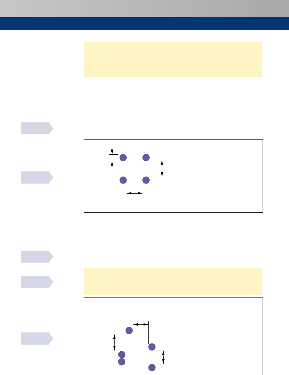
104
BS EN 1992-1-1
fig. 8.14
BS EN 1992-1-1
fig. 8.15
BS EN 1992-1-1
8.10.1.3 (3)
PD 6687-2
9.2
15.10
15.10.1
15.10.2
The spacing of the transverse reinforcement should not exceed twice the minimum
flangethickness.
Inskewvoidedslabs,itispreferableforthetransversesteeltobeplacedperpendiculartothe
voidsandthelongitudinalsteeltobeplacedparalleltothevoids.
Prestressing
Arrangement of pre-tensioned tendons
Theminimumclearhorizontalandverticalspacingofindividualpre-tensionedtendonsshould
beinaccordancewiththatshowninFigure15.9.
f
≥d
g
≥2f
≥d
g
+5
≥2f
≥20 mm
≥f
≥40 mm
≥d
g
+5
≥
f
≥50 mm
≥d
g
≥f
≥40 mm
Note
Wherefisthediameterof
pre-tensionedtendonand
g
isthe
maximumsizeofaggregate
Figure 15.9
Minimum clear spacing between pre-tensioned tendons
Arrangement of post-tensioned ducts
The minimum clear spacing of between ducts should be in accordance with that shown in
Figure15.10.
Intheabsenceoftheprovisionofreinforcementbetweenductstopreventsplittingofthe
concrete,designedinaccordancewiththestrutandtierules(seeSection10),theminimum
centretocentreductspacingsshouldbeasgiveninTable15.3.Thesespacingsaregivenin
BS5400-4:1990
[24]
.
f
≥d
g
≥2f
≥d
g
+5
≥2f
≥20 mm
≥f
≥40 mm
≥d
g
+5
≥
f
≥50 mm
≥d
g
≥f
≥40 mm
Note
Wherefisthediameterof
post-tensionedductand
g
isthe
maximumsizeofaggregate
Figure 15.10
Minimum clear spacing between post-tensioned ducts
BS EN 1992-1-1
8.10.1.2(1)

105
Detailing–particularrequirements
Table 15.3
Minimum spacing of post-tensioning ducts (mm)
Radius of
curvature of
duct (m)
Duct internal diameter (mm)
19 30 40 50 60 70 80 90 100 110 120 130 140 150 160 170
Tendon force (kN)
296 387 960 1337 1920 2640 3360 4320 5183 6019 7200 8640 9424 10336 11248 13200
2
110 140 350 485 700 960
4
55 70 175 245 350 480 610 785 940 Radiinot
normallyused
6
38 60 120 165 235 320 410 525 630 730 870 1045
8
90 125 175 240 305 395 470 545 655 785 855 940
10
80 100 140 195 245 315 375 440 525 630 685 750 815
12
160 205 265 315 365 435 525 570 625 680 800
14
140 175 225 270 315 375 450 490 535 585 785
16
160 195 235 275 330 395 430 470 510 600
18
180 210 245 290 350 380 420 455 535
20
200 220 265 315 345 375 410 480
22
240 285 310 340 370 435
24
265 285 315 340 400
26
260 280 300 320 370
28
345
30
340
40
38 60 80 100 120 140 160 180 200 220 240 260 280 300 320 340
Notes
1Thetendonforceshownisthemaximumnormallyavailableforthegivensizeofduct(takenas80%ofthecharacteristicstrengthofthetendon).
2Valueslessthan2×ductinternaldiameterarenotincluded.
Connections
Connections transmitting compression
Connections without bedding material (dry connections) should only be used where an
appropriatequalityof workmanshipcan be achieved.Theaveragebearingstressshouldnot
exceed0.3
cd
where
cd
=
0.85
ck
/
1.5
Intheabsenceofotherspecificationsthefollowingvaluecanbeusedforthebearingstrength
ofotherconnections
Rd
=
bed
≤0.85
cd
where
cd
=lowerofthedesignstrengthsforsupportedandsupportingmember
=
0.85
ck
/
1.5
bed
=designstrengthofthebeddingmaterial
15.11
15.11.1
PD 6687-2
table 3
BS EN 1992-1-1
10.9.4.3(3)
BS EN 1992-1-1
10.9.5.2(2)
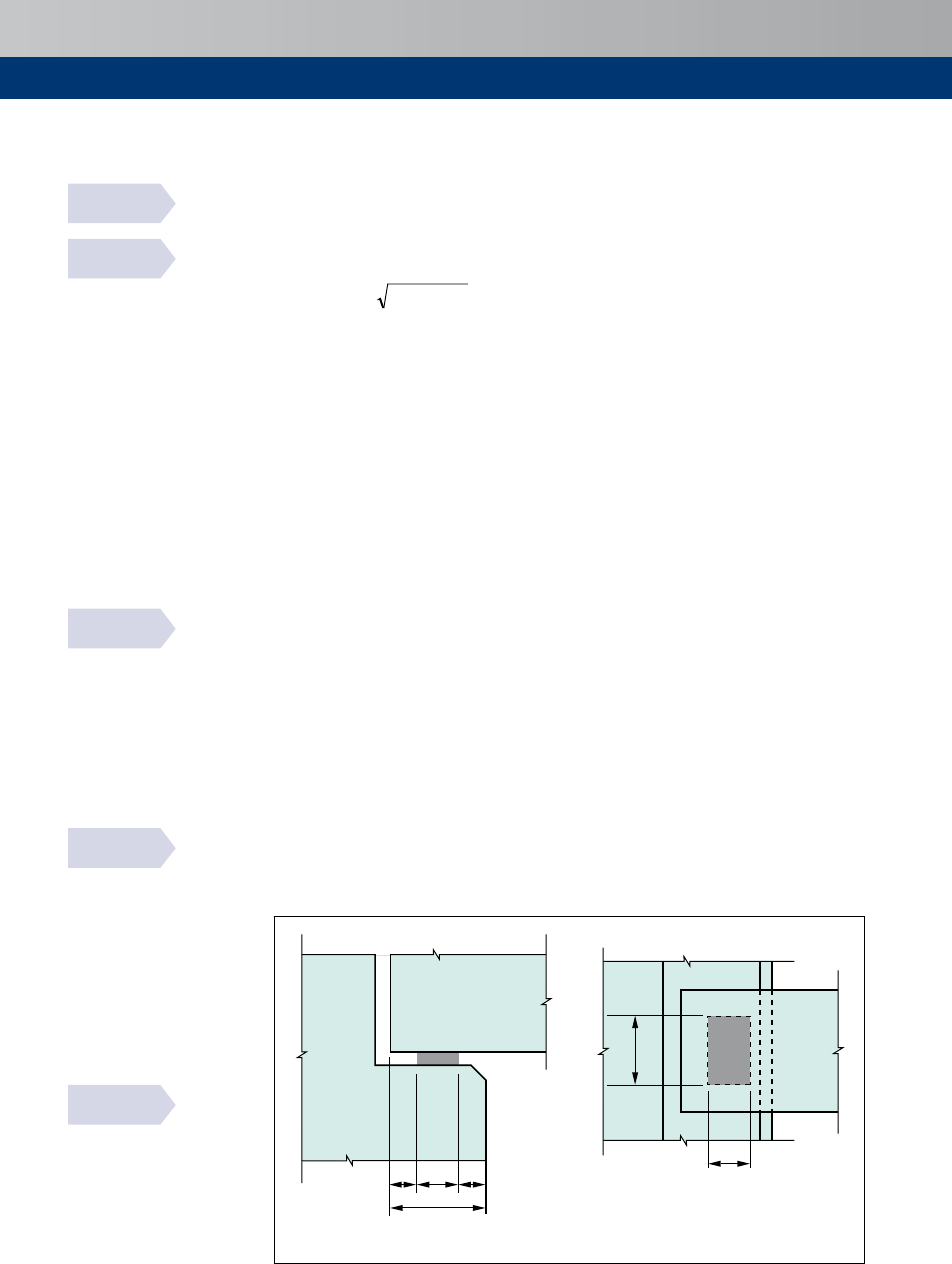
106
15.12
BS EN 1992-1-1
10.9.5.1(4)
BS EN 1992-1-1
10.9.5.2(1)
BS EN 1992-1-1
10.9.4.7(1)
BS EN 1992-1-1
10.9.5.2(3)
BS EN 1992-1-1
fig. 10.6
Bearings
Bearingsshallbedesignedanddetailedtoensurecorrectpositioningtakingintoaccountthe
productionandassemblingdeviations.
Thenominallength,,ofasimplebearingasshowninFigure15.11maybecalculatedas:
++=
Da
2
2
aa
1
+
a
2
+
a
3
Da
3
2
where
1
= netbearinglengthwithregardtobearingstress
1
=
Ed
/(
1
Rd
)butnotlessthan
minimumvaluesinTable15.4
Ed
= designvalueofsupportreaction
1
= netbearingwidth(seebelow)
Rd
= designvalueofbearingstrength(seeSection15.11.1)
2
= distanceassumedineffectivebeyondouterendofsupportingmember,seeFigure
15.11andTable15.5
3
= similardistanceforsupportedmember,seeFigure15.11andTable15.6
D
2
= allowancefordeviationsforthedistancebetweensupportingmembers,seeTable
15.7
D
3
= allowancefordeviationsforthelengthofsupportingmember
=
n
/2500
n
= lengthofmember
Theeffectivebearinglength
1
iscontrolledbyadistance,,(seeFigure15.12)fromtheedgeof
therespectiveelements
where
i
=
i
+D
i
withhorizontalloopsorotherwiseend-anchoredbars
i
=
i
+D
i
+
i
withverticallybentbars
where
i
= concretecover
D
i
= deviation
i
= bendradius
Ifmeasuresaretakentoobtainauniformdistributionofthebearingpressure,e.g.withmortar,
neopreneorsimilarpads,thedesignbearingwidth
1
maybetakenastheactualwidthofthe
bearing.Otherwise,andintheabsenceofamoreaccurateanalysis,
1
shouldnotbegreater
thanto600mm.
a) Elevation
b) Plan
Da
3
a
3
b
1
a
1
a
1
a
+
Da
2
a
2
+
Figure 15.11
Example of bearing with definitions

107
Detailing–particularrequirements
Figure 15.12
Example of
detailing
of reinforcement
in support
d
i
c
i
r
i
r
i
> a
1
+ Da
3
c
i
d
i
> a
1
+ Da
2
Table 15.4
Minimum value of
a
1
(mm)
Relative bearing stress, s
Ed
/ f
cd
≤0.15 0.15 – 0.4 >0.4
Line supports (floors, roofs)
25 30 40
Ribbed floors and purlins
55 70 80
Concentrated supports (beams)
90 110 140
Table 15.5
Distance a
2
(mm) assumed ineffective from outer end of supporting member
Support material and type Relative bearing stress, s
Ed
/ f
cd
≤0.15 0.15 – 0.4 >0.4
Steel line
concentrated
0
5
0
10
10
15
Reinforced concrete
≥ C30 line
concentrated
0
10
10
15
15
25
Plain concrete and reinforced concrete < C30 line
concentrated
10
15
15
25
25
35
Brickwork line
concentrated
10
20
15
25
a
a
Key
aConcretepadstoneshouldbeusedinthesecases
Table 15.6
Distance a
3
(mm) assumed ineffective beyond outer end of supported member
Detailing of reinforcement Support
Line Concentrated
Continuous bars over support (restrained or not) 0 0
Straight bars, horizontal, close to end of member 5 15,butnotlessthanendcover
Tendons or straight bars exposed at end of
member
5 15
Vertical loop reinforcement 15 Endcover+innerradiusofbending
BS EN 1992-1-1
fig.10.5
BS EN 1992-1-1
table 10.2
BS EN 1992-1-1
table 10.3
BS EN 1992-1-1
table 10.4

108
BS EN 1992-1-1
table 10.5
Table 15.7
Allowance Da
2
for tolerances for the clear distance between the faces of the supports
Support material Da
2
Steel or precast concrete 10≤/1200≤30mm
Brickwork or cast in-situ concrete 15≤/1200+5≤40mm
Note
=spanlength

109
Designfortheexecutionstages
16
Design for the execution stages
Forbridgesbuiltinstages,accountoftheconstructionprocedureshouldbeconsideredat
serviceabilityandultimatelimitstates.
Serviceabilitycriteriaforthecompletedstructureneednotbeappliedtointermediateexecution
stages,providedthatdurabilityandfinalappearanceofthecompletedstructurearenotaffected
(e.g. deformations). Even for bridges or elements of bridges in which the limit-state of
decompressionischeckedunderthequasi-permanentorfrequentcombinationofactionson
the completed structure, tensile stresses less than
1.0
ctm
() under the quasi-permanent
combinationofactionsduringexecutionarepermitted.Forbridgesorelementsofbridgesin
which the limit-state of cracking is checked under frequent combination on the completed
structure,thelimitstateofcrackingshouldbeverifiedunderthequasi-permanentcombination
ofactionsduringexecution.
BS EN 1992-2
113
BS EN 1992-2
113.3.2

110
Design aids
Thefollowingtext,tablesandfigureshavebeenderivedfromEurocode2andareprovidedas
anaidtodesignersintheUK.
Design for bending
Determinewhether ≤’ornot(i.e.whetherunder-reinforcedornot).
where
=
Ed
/(
2
ck
)
where
= effectivedepth=–cover–f
link
–f/2
= widthofsection
Forrectangularsections'maybedeterminedfromTable17.1or,forslabsonly,Table17.2
maybeused.'isdependentontheconcretestrengthandtheredistributionratioused.
Fornon-rectangularsection/limitsgiveninTable17.1maybeused.
If
≤',sectionisunder-reinforced.
Forrectangularsections:
s1
=
Ed
/
yd
where
s1
= areaoftensilereinforcement
Ed
= designmoment
yd
=
yk
/g
S
=500/
1.15
=434.8MPa
= [0.5+0.5(1–3.53n)
0.5
]≤0.95
n = factordefiningeffectivestrength
= 1.0–(
ck
–50)/200(seeTable6.1)
Forflangedbeamswhere<1.25
f
,
s1
=
Ed
/
yd
= depthtoneutralaxis
f
= thicknessofflange
For flanged beams where ≥ 1.25
f
, refer to
[
25
]
If >',sectionisover-reinforcedandrequirescompressionreinforcement.
s2
=(
Ed
–'
Ed
)/
sc
(–
2
)
where
s2
= compressionreinforcement
'
Ed
= '
2
ck
sc
= 700(
u
–
2
)/
u
≤
yd
where
2
=effectivedepthtocompressionreinforcement
u
=(d–l/z)
d =redistributionratio
When
yk
=500MPa,
sc
=
yd
unless
2
/
u
≥0.379.
Totalareaoftensionsteel
s1
='
Ed
/(
yd
)+
s2
sc
/
yd
17
17.1
Section 4

111
Designaids
Table 17.1
Limiting values of K' and x
u
/d
Percentage
redistribution
d
( Redistribution
ratio)
f
ck
50 55 60 70
n
1.000 0.975 0.950 0.900
l
0.800 0.788 0.775 0.750
e
cu2
0.0035 0.0031 0.0029 0.0027
k
1
or k
3
0.44 0.54 0.54 0.54
k
2
= k
4
1.251 1.310 1.357 1.409
0 1.00
' 0.167 0.132 0.123 0.110
u
/ 0.448 0.351 0.339 0.326
5 0.95
' 0.155 0.119 0.111 0.099
u
/ 0.408 0.313 0.302 0.291
1 0 0.90
' 0.142 0.107 0.099 0.088
u
/ 0.368 0.275 0.265 0.256
1 5 0.85
' 0.129 0.093 0.087 0.077
u
/ 0.328 0.237 0.228 0.220
Table 17.2
Limiting values of K' and x
u
/d for slabs
Percentage
redistribution
d
( Redistribution
ratio)
f
ck
50 55 60 70
n
1.000 0.975 0.950 0.900
l
0.800 0.788 0.775 0.750
e
cu2
0.0035 0.0031 0.0029 0.0027
k
1
or k
3
0.4 0.4 0.4 0.4
k
2
= k
4
1.000 1.048 1.086 1.127
0 1.00
' 0.207 0.193 0.181 0.163
u
/ 0.600 0.573 0.553 0.532
5 0.95
' 0.194 0.181 0.170 0.152
u
/ 0.550 0.525 0.507 0.488
1 0 0.90
' 0.181 0.169 0.158 0.141
u
/ 0.500 0.477 0.461 0.444
1 5 0.85
' 0.167 0.155 0.145 0.130
u
/ 0.450 0.429 0.415 0.399
2 0 0.80
' 0.152 0.141 0.132 0.118
u
/ 0.400 0.382 0.368 0.355
2 5 0.75
' 0.136 0.126 0.118 0.105
u
/ 0.350 0.334 0.322 0.311
3 0 0.70
' 0.120 0.111 0.103 0.092
u
/ 0.300 0.286 0.276 0.266

112
17.2
17.2.1
17.2.2
17.2.3
Design for beam shear
Requirement for shear reinforcement
If
Ed
>
Rd,c
thenshearreinforcementisrequired
where
Ed
=
Ed
/
w
,forsectionsshearreinforcement(i.e.slabs)
Rd,c
= shearresistancewithoutshearreinforcement,fromTable17.3
Table 17.3
Shear resistance without shear reinforcement, v
Rd,c
(MPa)
r
l
= A
sl
/b
w
d
Effective depth d (mm)
≤ 200 225 250 275 300 350 400 450 500 600 750
0.25% 0.54 0.52 0.50 0.48 0.47 0.45 0.43 0.41 0.40 0.38 0.36
0.50% 0.59 0.57 0.56 0.55 0.54 0.52 0.51 0.49 0.48 0.47 0.45
0.75% 0.68 0.66 0.64 0.63 0.62 0.59 0.58 0.56 0.55 0.53 0.51
1.00% 0.75 0.72 0.71 0.69 0.68 0.65 0.64 0.62 0.61 0.59 0.57
1.25% 0.80 0.78 0.76 0.74 0.73 0.71 0.69 0.67 0.66 0.63 0.61
1.50% 0.85 0.83 0.81 0.79 0.78 0.75 0.73 0.71 0.70 0.67 0.65
1.75% 0.90 0.87 0.85 0.83 0.82 0.79 0.77 0.75 0.73 0.71 0.68
≥2.00% 0.94 0.91 0.89 0.87 0.85 0.82 0.80 0.78 0.77 0.74 0.71
Notes
1 TablederivedfromBSEN1992-1-1andUKNationalAnnex.
2 Tablecreatedfor
ck
=30MPaassumingverticallinks.
3 Forr
l
≥0.4%and
ck
= 25MPa,applyfactorof0.94
ck
= 40MPa,applyfactorof1.10
ck
≥ 50MPa,applyfactorof1.19
ck
= 35MPa,applyfactorof1.05
ck
= 45MPa,applyfactorof1.14
Section capacity check
If
Ed,z
>
Rd,max
thensectionsizeisinadequate
where
Ed,z
=
Ed
/
w
=
Ed
/
w
0.9,forsectionsshearreinforcement
Rd,max
= capacityofconcretestrutsexpressedasastressintheverticalplane
=
Rd,max
/
w
=
Rd,max
/
w
0.9
Rd,max
canbedeterminedfromTable17.4,initiallycheckingatcoty=2.5.Shoulditbe
required,agreaterresistancemaybeassumedbyusingalargerstrutangle,y.
Shear reinforcement design
sw
/≥
Ed,z
w
/
ywd
coty
where
sw
= areaofshearreinforcement(verticallinksassumed)
= spacingofshearreinforcement
Ed,z
=
Ed
/
w
asbefore
w
= breadthoftheweb
ywd
=
ywk
/g
S
=designyieldstrengthofshearreinforcement
Alternatively,
sw
/permetrewidthof
w
maybedeterminedfromFigure17.1a)or17.1b)as
indicatedbythebluearrowsinFigure17.1a).Thesefiguresmayalsobeusedtoestimatethe
valueofcoty.
Section 7.3.2
Section 7.3.3
Section 7.2

113
Designaids
Beamsaresubjecttoaminimumshearlinkprovision.Assumingverticallinks,
sw,min
/
w
≥0.08
ck
0.5
/
yk
(seeTable17.5).
Table 17.4
Capacity of concrete struts expressed as a stress, v
Rd,max
, where z = 0.9d
f
ck
v
Rd,max
(MPa)
v
cot y 2.50 2.14 1.73 1.43 1.19 1.00
y
21.8º 25º 30º 35º 40º 45º
25
3.10 3.45 3.90 4.23 4.43 4.50 0.540
30
3.64 4.04 4.57 4.96 5.20 5.28 0.528
35
4.15 4.61 5.21 5.66 5.93 6.02 0.516
40
4.63 5.15 5.82 6.31 6.62 6.72 0.504
45
5.09 5.65 6.39 6.93 7.27 7.38 0.492
≥50
5.52 6.13 6.93 7.52 7.88 8.00 0.480
Notes
1 TablederivedfromBSEN1992-1-1andUKNationalAnnexassumingverticallinks,i.e.cota=0
2 v=0.6[1–(
ck
/250)]
3
Rd,max
=
cd
(coty+cota)/(1+cot
2
y)
Table 17.5
Values of A
sw,min
/sb
w
× 10
3
for beams for vertical links and f
yk
= 500 MPa
Concrete class
C20/25 C25/30 C30/37 C35/45 C40/50 C45/55 ≥C50/60
sw,min
w
x10
3
0.72 0.80 0.88 0.95 1.01 1.07 1.13
4.0
3.0
2.0
5.0
6.0
7.0
8.0
02468
10
12
14
C35/45
C40/50
C45/55
0.0
1.0
2.14 1.73 1.43
1.19
1.00
SeeFig.17.1b)
A
sw
/srequired per metre width of b
w
f
ywk
= 500 MPa
v
Rd,max
forcoty=2.5
v
Ed,z
(MPa)
C30/37
C20/25
C25/30
≥C50/60
Figure 17.1a)
Diagram to determine A
sw
/s required (for beams with high shear stress)
Section 15.2.6

114
C20/25
C25/30
C30/37
C30/37
C35/45
C40/50
C45/55
C50/60
4.0
3.0
2.0
1.0
0.0
0
1
2
3
4
f
ywk
= 500 MPa
sw,min
/
forbeams
Rangeof
Rd,c
forrange
=200mm,r=2.0%
to
=750mm,r=0.5%
C25/30
A
sw
/srequired per metre width of b
w
v
Ed,z
(MPa)
C20/25
Figure 17.1b)
Diagram to determine A
sw
/s required (for slabs and beams with low shear stress)
Design for punching shear
Determine if punching shear reinforcement is required, initially at
1
, then if necessary at
subsequentperimeters,
i
.
If
Ed
>
Rd,c
thenpunchingshearreinforcementisrequired
where
Ed
= b
Ed
/
i
where
b =factordealingwitheccentricity(seeSection8.2)
Ed
=designvalueofappliedshearforce
i
=lengthoftheperimeterunderconsideration(seeSections8.3,8.7and15.4.3)
=meaneffectivedepth
Rd,c
=shearresistancewithoutshearreinforcement(seeTable17.3)
Forverticalshearreinforcement
(
sw
/
r
)=
1
(
Ed
–0.75
Rd,c
)/(1.5
ywd,ef
)
where
sw
= areaofshearreinforcementinoneperimeteraroundthecolumn.
For
sw,min
seeSection15.4.3
r
= radialspacingofperimetersofshearreinforcement
1
= basiccontrolperimeter(seeFigures8.3and8.4)
ywd,ef
= effectivedesignstrengthofreinforcement=(250+0.25)≤
ywd
.ForClass500
shearreinforcementseeTable17.6
Table 17.6
Values of f
ywd, ef
for Class 500 reinforcement
d
150 200 250 300 350 400 450
f
ywd,ef
287.5 300 312.5 325 337.5 350 362.5
17.3
Section 8.21
Section 8.5
Section 15.4.3

115
Designaids
17.4
17.4.1
17.4.2
Design for axial load and bending
General
Incolumns,designmoments
Ed
anddesignappliedaxialforce
Ed
shouldbederivedfromanalysis,
considerationofimperfectionsand,wherenecessary,2ndordereffects(seeSection5.6).
Design by calculation
Assumingtwolayersofreinforcement,
s1
and
s2
,thetotalareaofsteelrequiredinacolumn,
s
,maybecalculatedasshownbelow.
Foraxialload
sN
/2 = (
Ed
–a
cc
n
ck
c
/g
C
)/(s
sc
–s
st
)
where
sN
= totalareaofreinforcementrequiredtoresistaxialloadusingthismethod.
sN
=
s1
+
s2
and
s1
=
s2
where
s1
(
s2
) = areaofreinforcementinlayer1(layer2)(seeFigure6.3)
Ed
= designvalueofaxialforce
a
cc
=
0.85
n = 1for≤C50/60(seeTable6.1when
ck
>50)
= breadthofsection
c
= effectivedepthofconcreteincompression=l≤
where
l = 0.8for≤C50/60(seeTable6.1when
ck
>50)
= depthtoneutralaxis
= heightofsection
g
C
=
1.5
s
sc
,(s
st
)= stressincompression(andtension)reinforcement
Formoment
sM
=
Ed
–a
cc
n
ck
c
(/2–
c
/2)/g
C
2 (/2–
2
)(s
sc
+s
st
)
where
sM
= totalareaofreinforcementrequiredtoresistmomentusingthismethod
sM
=
s1
+
s2
and
s1
=
s2
Solution:iterate suchthat
sN
=
sM
.
Section 5.6
Section 6.2.2

116
17.4.3
Column charts
Alternatively
s
maybeestimatedfromcolumncharts.
Figures17.2a)toe)givenon-dimensionaldesignchartsforsymmetricallyreinforcedrectangular
columnswherereinforcementisassumedtobeconcentratedinthecorners.
Inthesecharts:
a
cc
= 0.85
ck
≤ 50MPa
Simplifiedstressblockassumed.
s
= totalareaofreinforcementrequired
= (
s
yk
/
ck
)
ck
/
yk
where
(
s
yk
/
ck
) is derived from the appropriate design chart interpolating as necessary
betweenchartsforthevalueof
2
/forthesection.
Wherereinforcementisnotconcentratedinthecorners,aconservativeapproachistocalculate
aneffectivevalueof
2
asillustratedinFigures17a)toe).
2
=effectivedepthtosteelinlayer2.
Figures17.3a)toe)givenon-dimensionaldesignchartsforcircularcolumns.
0.3
0.4
0.5
0.6
0.7
0.8
0.9
1.0
1.3
1.2
1.1
1.0
0.9
0.8
0.7
0.6
0.5
0.4
0.3
0.2
0.1
0
0
0.05
0.10
0.15 0.20 0.25 0.30 0.35
0.40
0.45
0
0.1
0.2
0.3
0.4
0.5
0.6
0.7
0.8
0.9
1.0
Af bhf
s y
k c
k
/
K
r
= 0.2
Figure 15.5(a)
Rectangular columns /= 0.05dh
2
h/2
h
d
2
Centroid of bars in
half section
Ratio d
2
/h = 0.05
N/
Ed
/bhf
ck
M
Ed
/bh
2
f
ck
Figure 17.2a)
Rectangular columns (f
ck
≤ 50 MPa, f
yk
= 500 MPa) d
2
/h = 0.05

117
Designaids
h/2
h
d
2
Centroid of bars in
half section
0.3
0.4
0.5
0.6
0.7
0.8
0.9
1.3
1.2
1.1
1.0
0.9
0.8
0.7
0.6
0.5
0.4
0.3
0.2
0.1
0
0 0.05
0.10 0.15 0.20
0.25
0.30
0.35
0.40
0.45
K
r
=1
K
r
= 0.2
0
0.1
0.2
0.3
0.4
0.5
0.6
0.7
0.8
0.9
1.0
Figure 15.5(b)
Rectangular columns /= 0.10dh
2
A f bhf
s yk
/
c
k
Ratio d
2
/h = 0.10
N
Ed
/bhf
ck
M
Ed
/bh
2
f
ck
Figure 17.2b)
Rectangular columns (f
ck
≤ 50 MPa, f
yk
= 500 MPa) d
2
/h = 0.10
h/2
h
d
2
Centroid of bars in
half section
0.3
0.4
0.5
0.6
0.7
0.8
0.9
0
0.1
0.2
0.3
0.4
0.5
0.7
0.9
1.0
1.3
1.2
1.1
1.0
0.9
0.8
0.7
0.6
0.5
0.4
0.3
0.2
0.1
0
0
0.05
0.10 0.15 0.20 0.25
0.30
0.35
0.40
A f
bhf
s y
k c
k
/
K
r
=1
K
r
= 0.2
Figure 15.5(c)
Rectangular columns /= 0.15dh
2
0.6
0.8
Ratio d
2
/h = 0.15
M
Ed
/bh
2
f
ck
N/
Ed
/bhf
ck
Figure 17.2c)
Rectangular columns (f
ck
≤ 50 MPa, f
yk
= 500 MPa) d
2
/h = 0.15

118
h/2
h
d
2
Centroid of bars in
half section
0 0.05
0.10
0.15 0.20 0.25 0.30
0.35
0
0.1
0.2
0.3
0.4
0.5
0.6
0.7
0.8
0.9
1.0
1.2
1.1
1.3
0.3
0.4
0.5
0.6
0.7
0.8
0.9
A f
bhf
s yk c
k
/
Ratio d
2
/h = 0.20
Figure 15.4(d)
Rectangular columns /= 0.20dh
2
K
r
= 1
K
r
= 0.2
0
0.1
0.2
0.3
0.4
0.5
0.6
0.7
0.8
0.9
1.0
N/
Ed
/bhf
ck
M
Ed
/bh
2
f
ck
Figure 17.2d)
Rectangular columns (f
ck
≤ 50 MPa, f
yk
= 500 MPa) d
2
/h = 0.20
A f
bhf
s yk ck
/
Figure 15.5(e)
Rectangular columns /= 0.25dh
2
K
r
= 0.2
0.3
0.4
0.5
0.6
0.7
0.8
0.9
1.3
1.2
1.1
1.0
0.9
0.8
0.7
0.6
0.5
0.4
0.3
0.2
0.1
0
0 0.05 0.10 0.15
0.20
0.25
0.30
1.0
0.9
0. 8
0.7
0.6
0.5
0.4
0.3
0.2
0.1
0
K
r
= 1
h/2
h
d
2
Centroid of bars in
half section
N/
Ed
/bhf
ck
M
Ed
/bh
2
f
ck
Ratio d
2
/h = 0.25
Figure 17.2e)
Rectangular columns (f
ck
≤ 50 MPa, f
yk
= 500 MPa) d
2
/h = 0.25

119
Designaids
K
r
=1
0.9
0.8
0.7
0.6
0.5
0.4
0.3
1.0
0.8
0.7
0.6
0.5
0.4
0.3
0.2
0.1
0
0.2
1.2
1.1
1.0
0.9
0.8
0.7
0.6
0.5
0.4
0.3
0.2
0.1
0
0 0.01 0.02 0.03 0.04 0.05
0.06
0.07
0.9
d
h
File Concise Eurocode
Circular Columns 0.6
v1 10.11.08
A
s
f
yk
/h
2
f
ck
Ratio d/h = 0.6
N
Ed
/h
2
f
ck
M
Ed
/h
3
f
ck
Figure 17.3a)
Rectangular columns (f
ck
≤ 50 MPa, f
yk
= 500 MPa) d
2
/h = 0.6
1.2
1.1
1.0
0.9
0.8
0.7
0.6
0.5
0.4
0.3
0.2
0.1
0
0 0.02 0.04
0.06
0.08
0.10
0.12
0.2
0.3
0.4
0.5
0.6
0.7
0.8
1.0
0.9
0.8
0.7
0.6
0.5
0.4
0
0.1
0.2
0.3
File Concise Eurocode
d
h
Ratio d/h = 0.7
N
Ed
/h
2
f
ck
M
Ed
/h
3
f
ck
K
r
=1
A
s
f
yk
/h
2
f
ck
Figure 17.3b)
Rectangular columns (f
ck
≤ 50 MPa, f
yk
= 500 MPa) d
2
/h = 0.7

120
d
h
1.2
1.1
1.0
0.9
0.8
0.7
0.6
0.5
0.4
0.3
0.2
0.1
0
0 0.02 0.04
0.06
0.08 0.10 0.12 0.14
0.16
0.18 0.20
0.2
0.3
0.4
0.5
0.6
0.7
0.8
0.9
1.0
0.9
0.8
0.7
0.6
0.5
0.4
0.3
0.2
0.1
0
Ratio d/h = 0.8
A
s
f
yk
/h
2
f
ck
K
r
=1
N
Ed
/h
2
f
ck
M
Ed
/h
3
f
ck
Figure 17.3c)
Rectangular columns (f
ck
≤ 50 MPa, f
yk
= 500 MPa) d
2
/h = 0.8
d
h
0.2
0.3
1.0
0.9
0.8
0.7
0.6
0.5
0.4
0.3
0.2
0
0.4
0.5
0.6
0.7
0.8
0.9
0 0.05 0.10 0.15 0.20 0.25
1.2
1.1
1.0
0.9
0.8
0.7
0.6
0.5
0.4
0.3
0.2
0.1
0
0.1
File Concise Eurocode
Circular Columns 0.85
Ratio d/h = 0.85
K
r
=1
A
s
f
yk
/h
2
f
ck
N
Ed
/h
2
f
ck
M
Ed
/h
3
f
ck
Figure 17.3d)
Rectangular columns (f
ck
≤ 50 MPa, f
yk
= 500 MPa) d
2
/h = 0.85
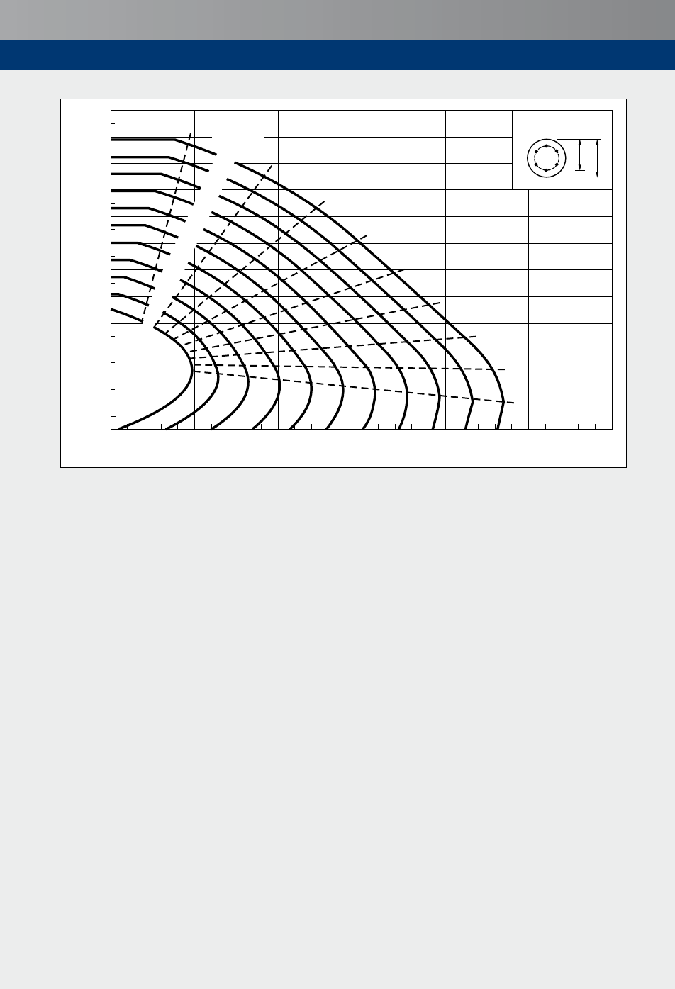
121
Designaids
d
h
0.05 0.10 0.15 0.20 0.25 0.30
0.7
0.2
0.3
0.4
0.5
0.6
0.8
0.9
1.0
0.9
0.8
0.7
0.6
0.5
0.4
0.3
0.2
0.1
0
1.2
1.1
1.0
0.9
0.8
0.7
0.6
0.5
0.4
0.3
0.2
0.1
0
0
File Concise Eurocode
Circular Columns 0.9
v1 10.11.08
Ratio d/h = 0.9
K
r
=1
A
s
f
yk
/h
2
f
ck
N
Ed
/h
2
f
ck
M
Ed
/h
3
f
ck
Figure 17.3e)
Rectangular columns (f
ck
≤ 50 MPa, f
yk
= 500 MPa) d
2
/h = 0.9

122
18 References
1 BRITISHSTANDARDSINSTITUTION.BSEN1992-1-1,Eurocode2–
Part1-1:BSI,2004,incorporatingcorrigendum
dated12-11-2007.
1a NationalAnnextoEurocode2–Part1-1.BSI,2005.
2 BRITISHSTANDARDSINSTITUTION.BSEN1992-2,Eurocode2–
Part2:BSI,2005,incorporatingcorrigendum
dated12-11-2007.
2a NationalAnnextoEurocode2–Part2.BSI,2007.
3 BRITISHSTANDARDSINSTITUTION.PD6687-2
2005.BSI,2008.
4 WOOD,RH.Thereinforcementofslabsinaccordancewithapre-determinedfieldof
moments1968,No.2,pp.69–76.
5 DENTON,SR&BURGOYNE,CJ.Theassessmentofreinforcedconcreteslabs.
,7thMay1996,Vol.74,No.9,pp.147–152.
6 BRITISHSTANDARDSINSTITUTION.PD6687
BSI,2006.
7 BRITISHSTANDARDSINSTITUTION.BSEN1990,Eurocode:BSI,2002,
incorporatingamendmentNo.1.
7a NationalAnnextoEurocode.BSI,2004,incorporatingamendmentNo.1.
8 BRITISHSTANDARDSINSTITUTION.BS8500-1:–
BSI,2006.
9 BRITISHSTANDARDSINSTITUTION.BSEN1991,Eurocode1:(10parts).
BSI,2002–2006.
9a NationalAnnexestoEurocode1.BSI,2005–2009andinpreparation.
10 BRITISHSTANDARDSINSTITUTION.ENV13670-1:2008:
BSI,2000.
11 BRITISHSTANDARDSINSTITUTION.BSEN13670..BSI,
due2009.
12 BRITISHSTANDARDSINSTITUTION.BSEN1997,Eurocode7:
.BSI,2004.
12a NationalAnnextoEurocode7–Part1.BSI,2007.
13 BRITISHSTANDARDSINSTITUTION.PD6694-1
BSI,due2009.
14 BRITISHSTANDARDSINSTITUTION.BSEN206-1.
BSI,2000.
15 BRITISHSTANDARDSINSTITUTION.BSEN197-1
BSI,2000.
16 BRITISHSTANDARDSINSTITUTION.BS4449:
BSI,2005.
17 BRITISHSTANDARDSINSTITUTION.BSEN10080:
BSI,2005.
18 BRITISHSTANDARDSINSTITUTION.BS5896.
BSI,1980,incorporatingamendmentNo.1.
19 BUILDINGRESEARCHESTABLISHMENT.BRESpecialDigest1.
BRE,2005.

123
References
20 HENDY,CR&SMITH,DA.ThomasTelford,2007.
21 ENV1992-1-1:Eurocode2:
BSI,1992(supersededbyreference1).
22 INTERNATIONALSTANDARDSORGANISATION,ISO/FDIS.17660-2:
.ISO,2005.
23 BRITISHSTANDARDSINSTITUTION.BSEN1536:
BSI,2000.
24 BRITISHSTANDARDSINSTITUTION.BS5400:S
BSI,1990.
25 BROOKER,Oetal.TheConcreteCentre,
2006.

3
Guide to presentation
Grey shaded text,
tables and gures
Modied Eurocode 2 text and additional text, derived
formulae, tables and illustrations not from Eurocode 2
Yellow shaded text,
tables and gures
Additional text from PD 6687
[6]
or PD 6687-2
[3]
BS EN 1992-1-1
6.4.4
Relevant code and clauses or gure numbers
BS EN 1992-1-1
NA
From the relevant UK National Annex
BS EN 1992-1-1
6.4.4 & NA
From both Eurocode 2-1-1 and UK National Annex
Section 5.2
Relevant parts of this publication
1.0
Nationally Determined Parameter. UK values have
been used throughout

4
Concise Eurocode 2 for Bridges
This publication summarises the material that will
be commonly used in the design of reinforced and
prestressed concrete bridges using Eurocode 2.
With extensive clause referencing, readers are guided through
Eurocode 2, other relevant European standards and non-
contradictory complementary information. The publication,
which includes design aids, aims to help designers with the
transition to design using Eurocodes.
Concise Eurocode 2 for Bridges is part of a range of resources
available from the cement and concrete industry to assist
engineers with the design of a variety of concrete bridges. For
more information visit www.concretecentre.com
Owen Brooker is senior structural engineer for The
Concrete Centre. He is author of several publications,
including the well received series How to design concrete
structures using Eurocode 2. He regularly lectures and
provides training to structural engineers, particularly on the
application of Eurocode 2.
Paul Jackson is a technical director of Gifford, which he
joined from BCA in 1988. He has worked on bridge design,
assessment, construction, strengthening and research. He
has contributed extensively to codes of practice and is
currently a member of the BSI committee for bridges and
convenor of its working group for concrete bridges. He
served on the project team for EN 1992-2.
Stephen Salim is a senior engineer with Gifford. He has
worked on bridge assessment, feasibility studies, design,
construction supervision and research. He was also involved
in the calibration work of BS EN 1992-2; some of the
proposals arising from this work were adopted in the UK
National Annex.
CCIP-038
Published 2009
ISBN 978-1-904818-82-3
Price Group P
© MPA – The Concrete Centre
Riverside House, 4 Meadows Business Park,
Station Approach, Blackwater, Camberley, Surrey, GU17 9AB
Tel: +44 (0)1276 606800 Fax: +44 (0)1276 606801
www.concretecentre.com
