
Cordex HP Controller
Software Manual
Technical Guide: 0350058-J0
Effective: 08/2020
Cordex HP Controller Software Manual
NOTE: Photographs contained in this manual are for illustrative purposes only. These photographs may
not match your installation.
NOTE: Operator is cautioned to review the drawings and illustrations contained in this manual before
proceeding. If there are questions regarding the safe operation of this powering system, contact Alpha
Technologies or your nearest Alpha representative.
NOTE: Alpha
®
shall not be held liable for any damage or injury involving its enclosures, power
supplies, generators, batteries, or other hardware if used or operated in any manner or subject to any
condition inconsistent with its intended purpose, or if installed or operated in an unapproved manner,
or improp-erly maintained.
)RUWHFKQLFDOVXSSRUWFRQWDFW$OSKD7HFKQRORJLHV
&DQDGDDQG86$
,QWHUQDWLRQDO
Copyright
Copyright © 2020 Alpha Technologies Ltd. All rights reserved. Alpha is a registered trademark of Alpha
Technologies Services Inc.
No part of this documentation shall be reproduced, stored in a retrieval system, translated, transcribed,
or transmitted in any form or by any means manual, electric, electronic, electromechanical, chemical,
optical, or other-wise without prior explicit written permission from Alpha Technologies.
This document, the software it describes, and the information and know-how they contain constitute the
proprietary, confidential and valuable trade secret information of Alpha Technologies, and may not be
used for any unauthorized purpose, or disclosed to others without the prior written permission of Alpha
Technologies.
The material contained in this document is for information only and is subject to change without notice.
While reasonable efforts have been made in the preparation of this document to assure its accuracy,
Alpha Technologies assumes no liability resulting from errors or omissions in this document, or from the
use of the information contained herein. Alpha Technologies reserves the right to make changes in the
product design without reservation and without notification to its users.
Contents
List of Figures............................................................................................................................................. 12
List of Tables...............................................................................................................................................16
1. Safety..................................................................................................................................................... 17
2. Software Release History.................................................................................................................... 20
2.1. Application Release 6.30............................................................................................................. 20
2.2. Application Release 6.20............................................................................................................. 20
2.3. Application Release 6.10............................................................................................................. 20
2.4. Application Release 6.00............................................................................................................. 21
2.5. Application Release 5.20............................................................................................................. 21
2.6. Application Release 5.10............................................................................................................. 22
2.7. Application Release 5.01............................................................................................................. 22
2.8. Application Release 5.00............................................................................................................. 23
2.9. OS Release 6.30..........................................................................................................................23
2.10. OS Release 6.20........................................................................................................................23
2.11. OS Release 6.00........................................................................................................................24
2.12. OS Release 5.20........................................................................................................................24
2.13. OS Release 4.70........................................................................................................................24
2.14. OS Release 2.20........................................................................................................................24
2.15. Known Issues............................................................................................................................. 24
3. Introduction........................................................................................................................................... 27
3.1. Using the CXC HP Software Manual...........................................................................................27
3.1.1. Purpose and Audience...................................................................................................... 27
3.1.2. Knowledge and Permissions..............................................................................................27
3.2. Product Overview......................................................................................................................... 27
3.2.1. What Does the CXC HP Do?............................................................................................ 28
3.2.2. Typical System Configuration............................................................................................ 29
3.2.3. How to Get Help................................................................................................................ 29
4. Getting Started......................................................................................................................................32
4.1. Applying Power............................................................................................................................ 32
4.2. Connecting the Controller............................................................................................................ 32
4.2.1. In-Shelf Controller.............................................................................................................. 34
4.3. Navigating the CXC HP User Interface....................................................................................... 34
Page 2 0350058-J0 Rev AD
Cordex HP Controller Software Manual
4.3.1. Logging in to the Controller............................................................................................... 34
4.3.2. Controller Menu Map......................................................................................................... 35
4.3.3. Overview of the LCD Interface.......................................................................................... 36
4.3.4. Overview of the Web Interface.......................................................................................... 47
4.3.5. Overview of the In-Shelf Display....................................................................................... 58
4.4. Email Notification..........................................................................................................................61
4.5. Setting up SNMP Communication............................................................................................... 64
4.6. Setting up Modbus Communication.............................................................................................65
5. DC Power Systems.............................................................................................................................. 67
5.1. Guidelines for Commissioning the DC System............................................................................67
5.1.1. The Battery Mode.............................................................................................................. 68
5.2. DC System Functions.................................................................................................................. 68
5.2.1. Modules, Inventory and System Functions........................................................................68
5.2.2. Mixed Rectifier System...................................................................................................... 69
5.2.3. Battery Charging................................................................................................................ 70
5.2.4. Battery Temperature Compensation.................................................................................. 71
5.2.5. Battery Runtime and Health Estimation.............................................................................72
5.2.6. Low Voltage Disconnect Operation....................................................................................73
5.2.7. Battery Test........................................................................................................................ 74
5.2.8. Power Save........................................................................................................................76
5.3. Creating a DC System Manually................................................................................................. 77
5.3.1. Quick Reference for Configuring a DC System.................................................................78
5.3.2. Creating a DC System.......................................................................................................79
5.3.3. Configure the Basic DC System Settings..........................................................................82
5.3.4. Configure Dynamic Thresholds for Output Voltage Alarms............................................... 82
5.3.5. Configure the Rectifiers..................................................................................................... 82
5.3.6. Configure the Shunts......................................................................................................... 84
5.3.7. Configure the Loads.......................................................................................................... 84
5.3.8. Configure the Current Transducer..................................................................................... 85
5.3.9. Configure the General Purpose Transducer......................................................................85
5.3.10. Configure the Disconnects...............................................................................................86
5.3.11. Configure the Battery Parameters................................................................................... 87
5.3.12. Configure the Battery Temperature Sensors................................................................... 89
5.3.13. Configure the Charging System Function........................................................................90
0350058-J0 Rev AD Page 3
Cordex HP Controller Software Manual
5.3.14. Configure the Temperature Compensation System Function.......................................... 91
5.3.15. Configure Battery Runtime and Health Estimation.......................................................... 92
5.3.16. Run a Manual Battery Test.............................................................................................. 92
5.3.17. Configure Power Save..................................................................................................... 93
5.4. Connecting to Other Systems......................................................................................................93
5.4.1. Representing a Converter System as a DC Load............................................................. 94
5.4.2. Representing an Inverter System as a DC Load...............................................................94
6. Converter Systems...............................................................................................................................96
6.1. Introduction to Converter Systems...............................................................................................96
6.2. Creating a Converter System...................................................................................................... 97
6.2.1. Creating a System from a Configuration File.................................................................... 98
6.3. Configure the Converters............................................................................................................. 99
6.4. Configure the Shunts................................................................................................................... 99
6.5. Configure the Loads...................................................................................................................100
6.6. Configure the Current Transducer............................................................................................. 100
6.7. Configure the General Purpose Transducer.............................................................................. 101
7. Inverter Systems (Single T2S).......................................................................................................... 102
7.1. Introduction to Inverter Systems................................................................................................ 102
7.1.1. Components of a Single T2S Inverter System................................................................ 102
7.1.2. Quick Reference for Configuring an Inverter System...................................................... 104
7.1.3. Phase and Group Data....................................................................................................104
7.1.4. Live Alerts........................................................................................................................ 105
7.1.5. System Functions.............................................................................................................105
7.2. Creating an Inverter System...................................................................................................... 106
7.2.1. Creating a System from a Configuration File.................................................................. 106
7.3. Assigning a T2S.........................................................................................................................107
7.4. Commissioning a Single T2S Inverter System.......................................................................... 107
7.5. Configure the T2S......................................................................................................................109
7.6. Configure the Inverters.............................................................................................................. 110
7.7. Configure the Bypass Switch.....................................................................................................111
7.8. Configure the Breaker or Fuse.................................................................................................. 113
8. Line Power Systems.......................................................................................................................... 115
8.1. Introduction to Line Power Systems.......................................................................................... 115
8.1.1. Components of a Line Power System............................................................................. 115
Page 4 0350058-J0 Rev AD
Cordex HP Controller Software Manual
8.1.2. Quick Reference for Configuring a Line Power System.................................................. 117
8.2. Creating a Line Power System.................................................................................................. 117
8.2.1. Creating a System from a Configuration File.................................................................. 118
8.3. Configure the Line Power Modules........................................................................................... 118
8.3.1. Shared Alarm Configuration.............................................................................................119
8.4. Line Power Module Alarms........................................................................................................119
8.5. Configure the Line Power System Channels.............................................................................120
8.6. Configure the Line Power System Loads.................................................................................. 120
8.7. Line Power System Layout........................................................................................................ 121
8.7.1. Using the Layout Screen to View Module Status............................................................ 121
8.7.2. Using the Layout Screen to View Load Status................................................................122
8.7.3. Using the Layout Screen to Assign Channels to Loads.................................................. 123
9. Auxiliary Systems...............................................................................................................................126
9.1. Introduction to Auxiliary Systems...............................................................................................126
9.2. Create an Auxiliary System....................................................................................................... 126
9.2.1. Creating a System from a Configuration File.................................................................. 126
9.3. Current Transducers...................................................................................................................126
9.4. Configure the Current Transducer............................................................................................. 126
9.5. Configure the General Purpose Transducer.............................................................................. 127
10. Distribution Systems........................................................................................................................128
10.1. Introduction to Distribution Systems........................................................................................ 128
10.2. Creating a Distribution System................................................................................................ 129
10.2.1. Creating a System from a Configuration File................................................................ 130
10.3. Distribution Subsystems...........................................................................................................130
10.4. Create a Smart Subsystem......................................................................................................130
10.5. Create a User Defined Subsystem.......................................................................................... 132
10.6. Configure the Panel Details..................................................................................................... 133
10.7. Configure the Breaker/Fuse Details.........................................................................................133
10.8. The Subsystem Layout............................................................................................................ 134
10.9. Map Shunts to ADIO Inputs.....................................................................................................135
11. DC Source Systems......................................................................................................................... 137
11.1. Creating a DC Source System.................................................................................................137
11.2. Create and Configure a DC Source.........................................................................................137
11.3. DC Generator........................................................................................................................... 138
0350058-J0 Rev AD Page 5
Cordex HP Controller Software Manual
11.3.1. Create and Configure a DC Generator..........................................................................138
11.4. DC Source System Effect on Other Systems.......................................................................... 139
12. AC Source Systems......................................................................................................................... 141
12.1. Creating an AC Source System...............................................................................................141
12.2. Create an AC Source...............................................................................................................141
12.2.1. Map Rectifiers to an AC Source....................................................................................142
12.3. AC Generator........................................................................................................................... 143
12.3.1. Create an AC Generator................................................................................................143
12.3.2. Configure Generator Control..........................................................................................144
13. FXM-HP Systems.............................................................................................................................. 145
14. Controller Redundancy....................................................................................................................146
15. Power Flow........................................................................................................................................147
15.1. Introduction to Power Flow...................................................................................................... 147
15.2. Accessing the Power Flow.......................................................................................................147
15.2.1. Getting Help................................................................................................................... 148
15.2.2. Using Power Flow Configuration Suggestions...............................................................148
15.2.3. Configuring the Default Power Flow.............................................................................. 149
15.3. Interacting with the Power Flow...............................................................................................149
15.4. Controller Power Flow..............................................................................................................150
15.5. Power Flow for Systems Managed by Different Controllers.................................................... 151
16. Maintaining the System................................................................................................................... 152
16.1. Rectifier Maintenance...............................................................................................................152
16.1.1. Rectifier Alarms..............................................................................................................152
16.1.2. Insert Unassigned Modules........................................................................................... 152
16.2. Inverter and T2S Maintenance................................................................................................ 152
16.2.1. Maintenance Bypass......................................................................................................153
16.2.2. Taking Power from DC Source...................................................................................... 153
16.2.3. Replace Fan...................................................................................................................154
16.2.4. Identifying an Inverter.................................................................................................... 155
16.2.5. Alarms and Alerts.......................................................................................................... 155
16.2.6. Replacing a T2S............................................................................................................ 155
16.2.7. Shelf Layout................................................................................................................... 156
16.3. Line Power System Maintenance............................................................................................ 156
16.3.1. Powering On and Off Line Power Loads.......................................................................156
Page 6 0350058-J0 Rev AD
Cordex HP Controller Software Manual
16.3.2. Replacing Line Power Modules..................................................................................... 156
16.4. Battery Maintenance................................................................................................................ 157
16.4.1. Battery Alarms................................................................................................................157
16.4.2. Charging Batteries......................................................................................................... 157
16.4.3. Maintaining Batteries......................................................................................................159
16.4.4. Battery Temperature Compensation.............................................................................. 163
16.5. Low Voltage Disconnect (LVD) Maintenance...........................................................................163
17. Maintaining the Controller...............................................................................................................165
17.1. Ethernet Communications........................................................................................................ 165
17.1.1. Connecting via the Web................................................................................................ 166
17.2. Working with Alarms, Alerts and Hints.................................................................................... 166
17.2.1. Active Alarms................................................................................................................. 166
17.2.2. Alerts.............................................................................................................................. 167
17.2.3. Hints............................................................................................................................... 167
17.2.4. Alarm Cut-off.................................................................................................................. 168
17.2.5. Alarm Activation Delay at Startup..................................................................................168
17.2.6. Alarm Summary Relays................................................................................................. 168
17.2.7. Creating User Alarms.....................................................................................................169
17.3. Controller Maintenance............................................................................................................ 170
17.3.1. Restarting the Controller................................................................................................ 170
17.3.2. Restarting via the LCD.................................................................................................. 171
17.3.3. Powering Down the Controller....................................................................................... 171
17.3.4. Changing the Time and Date.........................................................................................171
17.3.5. Changing the Language for the LCD.............................................................................172
17.3.6. Changing the Language for the Web Interface............................................................. 173
17.3.7. Changing User Interface Strings....................................................................................174
17.3.8. Changing the Web Session Language.......................................................................... 175
17.3.9. Changing the System Status Bar.................................................................................. 175
17.3.10. Changing the Dashboard Values................................................................................. 176
17.3.11. Data Sharing................................................................................................................ 177
17.4. Working with Logs....................................................................................................................178
17.4.1. Event and Alert Logs..................................................................................................... 178
17.4.2. Battery Log.....................................................................................................................179
17.4.3. Power Outage Log.........................................................................................................180
0350058-J0 Rev AD Page 7
Cordex HP Controller Software Manual
17.4.4. Datalogs......................................................................................................................... 180
17.4.5. Performance Logs..........................................................................................................184
17.5. File Maintenance...................................................................................................................... 185
17.5.1. File Preferences............................................................................................................. 185
17.5.2. File Maintenance via the LCD....................................................................................... 186
17.5.3. Upgrading the Controller Software................................................................................ 188
17.5.4. Exporting Configuration..................................................................................................188
17.5.5. Importing Configuration..................................................................................................190
17.5.6. Configuration Restore Points......................................................................................... 191
17.5.7. Exporting Diagnostic Information................................................................................... 193
17.5.8. Licensing........................................................................................................................ 193
17.5.9. Uploading the Software Manual.....................................................................................196
17.5.10. Exporting Inventory...................................................................................................... 196
17.6. User Account Maintenance...................................................................................................... 197
17.6.1. Setting Up Users and Permissions................................................................................197
17.6.2. Editing User Permissions...............................................................................................197
17.6.3. Enabling New Users...................................................................................................... 197
17.6.4. Disabling Users.............................................................................................................. 199
17.6.5. Changing the Default Password - LCD......................................................................... 200
17.6.6. Changing the Default Password - Web......................................................................... 200
17.6.7. Remote Configuration Lockout...................................................................................... 201
17.7. Remote Authentication............................................................................................................. 202
17.7.1. RADIUS Authentication..................................................................................................203
17.7.2. TACACS+ Authentication............................................................................................... 204
17.8. Flash Maintenance................................................................................................................... 206
17.8.1. Memory Status............................................................................................................... 206
17.8.2. Using Flash Refresh...................................................................................................... 207
17.9. Secure Web Server..................................................................................................................207
17.9.1. HTTPS And Certificate Overview.................................................................................. 207
17.9.2. Configuring HTTPS........................................................................................................ 208
17.10. VLAN Support........................................................................................................................ 210
17.11. Testing Relays........................................................................................................................ 212
18. Maintaining Modules........................................................................................................................ 213
18.1. ADIO Maintenance................................................................................................................... 213
Page 8 0350058-J0 Rev AD
Cordex HP Controller Software Manual
18.1.1. Configuring an ADIO......................................................................................................213
18.1.2. Replacing an ADIO........................................................................................................ 214
18.1.3. Calibrating Analog Inputs...............................................................................................215
18.1.4. Calibrating Shunts, Current Transducers and Temperature Probes.............................. 223
18.1.5. Testing Relays................................................................................................................226
18.1.6. Testing Comms Lost Action........................................................................................... 227
18.1.7. Enabling Temperature Sensor Failure Alarms............................................................... 227
18.1.8. Ground Fault Detection..................................................................................................228
18.2. Module Firmware Upgrades.....................................................................................................228
18.2.1. Module Firmware Upgrade............................................................................................ 228
18.2.2. Uploading a Firmware File.............................................................................................229
18.2.3. Selecting the File to Upgrade........................................................................................ 230
18.2.4. Upgrading the Module....................................................................................................231
19. Using Custom Views, Data, Timers, Counters, Scheduler and Custom Actions....................... 233
19.1. Using Custom Views................................................................................................................ 233
19.1.1. Creating Custom Views................................................................................................. 233
19.1.2. Adding Components in the Custom View.....................................................................233
19.1.3. Accessing and Configuring the Default Custom Dashboard View................................. 235
19.1.4. Accessing the Custom Data View................................................................................. 235
19.1.5. Removing a Table from the Custom View..................................................................... 236
19.1.6. Add an Existing Table to the Custom View................................................................... 236
19.2. Using Custom Data..................................................................................................................236
19.2.1. Configuring Custom Data...............................................................................................236
19.2.2. Creating Custom Data................................................................................................... 239
19.2.3. Creating Custom Data - Basic Work Flow.....................................................................239
19.2.4. Creating Custom Data - Detailed Work Flow................................................................ 239
19.2.5. Custom Data Examples................................................................................................. 241
19.2.6. Custom Data - Summing Load Shunts..........................................................................241
19.2.7. Custom Data - AC Cooling too Low User Alarm........................................................... 243
19.3. Using Timers............................................................................................................................ 244
19.3.1. Configuring the Delay Timer.......................................................................................... 245
19.3.2. Configuring the Interval Timer....................................................................................... 246
19.4. Using Counters.........................................................................................................................247
19.4.1. Configuring the Up Counter...........................................................................................247
0350058-J0 Rev AD Page 9
Cordex HP Controller Software Manual
19.4.2. Configuring the Down Counter...................................................................................... 248
19.5. Using Scheduler....................................................................................................................... 248
19.5.1. Configuring a Recurring Action......................................................................................249
19.6. Configuring a One-Time Action................................................................................................250
19.7. Configuring Scheduled Actions................................................................................................ 251
19.8. Using Scheduled Time Spans..................................................................................................252
19.9. Using Custom Actions..............................................................................................................253
19.9.1. Configuring a Change Relay Action.............................................................................. 253
19.9.2. Configuring a Change Field To Constant Action........................................................... 254
19.9.3. Configuring a Change Field To Variable Action.............................................................255
20. Troubleshooting................................................................................................................................257
20.1. Troubleshooting Your Controller...............................................................................................257
20.1.1. No Communication.........................................................................................................257
20.1.2. Unable to Communicate via Ethernet............................................................................257
20.1.3. Home Button or LCD Screen Not Responding..............................................................257
20.1.4. Controller Fail.................................................................................................................258
20.2. Troubleshooting a Rectifier System......................................................................................... 259
20.2.1. Relays Not Triggered During Alarm Conditions.............................................................259
20.2.2. Rectifier Alarms and Alerts............................................................................................ 259
20.2.3. Rectifier Not Acquired.................................................................................................... 259
20.2.4. Rectifier Communication Lost........................................................................................ 260
20.2.5. Replacing a Defective Rectifier......................................................................................260
20.2.6. Using Extended Ranges................................................................................................ 260
20.2.7. Rectifier Configuration Error.......................................................................................... 261
20.2.8. Rediscovering CAN Devices..........................................................................................262
20.2.9. Replacing a Defective ADIO..........................................................................................262
20.2.10. Troubleshooting a Battery Test.................................................................................... 262
20.2.11. Troubleshooting Power Save....................................................................................... 263
20.3. Troubleshooting an Inverter System........................................................................................ 264
20.3.1. Wrong Inverter AC Input Group.....................................................................................264
20.3.2. Wrong Inverter DC Input Group.....................................................................................264
20.3.3. T2S Expert Operations.................................................................................................. 265
20.3.4. Troubleshooting and Clearing the System Error Alarm................................................. 265
20.3.5. Phase Saturation Alarm................................................................................................. 266
Page 10 0350058-J0 Rev AD
Cordex HP Controller Software Manual
20.4. Troubleshooting a Line Power System.................................................................................... 266
20.4.1. Resolving Line Power System Alarms...........................................................................266
20.4.2. Fan Tray Alarms............................................................................................................ 267
20.4.3. Line Power System Overload........................................................................................ 267
20.4.4. Line Power System Transient Events............................................................................267
21. CXC HP Reference Guide................................................................................................................268
21.1. Modules.................................................................................................................................... 268
21.2. Communication Ports............................................................................................................... 269
21.2.1. Ethernet Ports................................................................................................................ 270
21.2.2. USB Ports...................................................................................................................... 270
21.2.3. CAN Ports...................................................................................................................... 270
21.3. Default System Values and Ranges........................................................................................ 272
21.3.1. 12V System Default Values and Ranges.......................................................................272
21.3.2. 24V System Default Values and Ranges.......................................................................273
21.3.3. 48V System Default Values and Ranges.......................................................................274
21.3.4. 125V System Default Values and Ranges.....................................................................275
21.3.5. 220V System Default Values and Ranges.....................................................................275
21.3.6. AC Voltage Alarm Ranges.............................................................................................276
22. Certification....................................................................................................................................... 277
23. Glossary.............................................................................................................................................278
24. Index................................................................................................................................................
0350058-J0 Rev AD Page 11
Cordex HP Controller Software Manual
List of Figures
Figure 1: CXC HP Controller (2RU model)...............................................................................................28
Figure 2: Typical DC System Configuration............................................................................................... 29
Figure 3: Accessing Help on the LCD Interface........................................................................................ 30
Figure 4: Accessing Help on the Web Interface........................................................................................ 30
Figure 5: Accounts and Shortcuts..............................................................................................................31
Figure 6: Menu Structure........................................................................................................................... 36
Figure 7: CXC HP Controller Dashboard...................................................................................................37
Figure 8: Maintenance Page...................................................................................................................... 38
Figure 9: System Maintenance Page.........................................................................................................38
Figure 10: LCD Menus............................................................................................................................... 39
Figure 11: Controller Status........................................................................................................................40
Figure 12: Time and Date.......................................................................................................................... 40
Figure 13: Timezone...................................................................................................................................41
Figure 14: Network Time Server................................................................................................................ 41
Figure 15: Synchronize Time..................................................................................................................... 42
Figure 16: Shortcuts................................................................................................................................... 42
Figure 17: Ethernet.....................................................................................................................................43
Figure 18: Inventory....................................................................................................................................43
Figure 19: Dashboard with Multi-system Panels........................................................................................44
Figure 20: Dashboard Using Wide Data Panel View.................................................................................44
Figure 21: Language.................................................................................................................................. 45
Figure 22: Browse USB..............................................................................................................................45
Figure 23: Export Diagnostic Information...................................................................................................46
Figure 24: Backup...................................................................................................................................... 46
Figure 25: Dashboard Overview on Web Interface....................................................................................48
Figure 26: Main Dashboard Tables............................................................................................................ 49
Figure 27: Table Icons................................................................................................................................49
Figure 28: Global Search Example............................................................................................................ 50
Figure 29: Web Interface Table Features...................................................................................................51
Figure 30: Controller Menu........................................................................................................................ 51
Figure 31: System Wizards........................................................................................................................ 52
Figure 32: Controller with No System Configured..................................................................................... 53
Page 12 0350058-J0 Rev AD
Cordex HP Controller Software Manual
Figure 33: Systems Data Tiles...................................................................................................................53
Figure 34: System Menu............................................................................................................................ 53
Figure 35: Modules Menu.......................................................................................................................... 55
Figure 36: Alarms Menu.............................................................................................................................55
Figure 37: Logs Menu................................................................................................................................ 56
Figure 38: Shelf Layout Menu....................................................................................................................57
Figure 39: In-Shelf Controller Dashboard Screens.................................................................................... 59
Figure 40: In-Shelf Controller Menu...........................................................................................................59
Figure 41: In-Shelf Controller Buttons: Vertical Mount...............................................................................60
Figure 42: In-Shelf Controller Buttons: Horizontal Mount.......................................................................... 61
Figure 43: Default Ports: SMTP Client and Server....................................................................................61
Figure 44: Default Ports: SNMP Manager and Agent................................................................................64
Figure 45: SNMP Destination Page:.......................................................................................................... 65
Figure 46: Destination 1 More Information Page:...................................................................................... 65
Figure 47: Default Ports: Modbus Client (Master) and Server (Slave)...................................................... 66
Figure 48: Enabling Modbus on the Controller.......................................................................................... 66
Figure 49: Battery Mode.............................................................................................................................68
Figure 50: Three-Stage Charging Cycle.................................................................................................... 70
Figure 51: Temperature Compensation Voltage Graph............................................................................. 72
Figure 52: Inhibit Disconnect......................................................................................................................73
Figure 53: Example of a DC System......................................................................................................... 78
Figure 54: Quick Reference for Configuring a DC System........................................................................79
Figure 55: Configure DC System Results Page........................................................................................ 81
Figure 56: Example Converter System...................................................................................................... 96
Figure 57: Quick Reference for Configuring a Converter System............................................................. 97
Figure 58: Create Converter System Wizard............................................................................................. 98
Figure 59: Single T2S Inverter System Components.............................................................................. 103
Figure 60: Quick Reference for Configuring an Inverter System............................................................. 104
Figure 61: Create Inverter System Wizard.............................................................................................. 106
Figure 62: Commission Inverter System Wizard......................................................................................108
Figure 63: Example LPS36 System......................................................................................................... 116
Figure 64: Example eLImiter+ System.....................................................................................................116
Figure 65: Quick Reference for Configuring a Line Power System......................................................... 117
Figure 66: Create Line System Wizard....................................................................................................118
0350058-J0 Rev AD Page 13
Cordex HP Controller Software Manual
Figure 67: Example of a DC System Distribution System....................................................................... 129
Figure 68: Example of BDFB Distribution Subsystem............................................................................. 131
Figure 69: Example of a User Defined Subsystem..................................................................................132
Figure 70: Distribution Subsystem Layout............................................................................................... 135
Figure 71: Power Flow for a DC System................................................................................................. 147
Figure 72: Navigating to Power Flow.......................................................................................................148
Figure 73: Power Flow Configuration Suggestions..................................................................................148
Figure 74: Interacting with the Power Flow............................................................................................. 149
Figure 75: Power Flow Controls...............................................................................................................150
Figure 76: Controller Power Flow............................................................................................................ 150
Figure 77: Using Data Sharing to Create Power Flow Across Different Controllers................................ 151
Figure 78: Add/Remove Inverters............................................................................................................ 153
Figure 79: Battery Charging Tables......................................................................................................... 158
Figure 80: Battery Maintenance System Functions................................................................................. 159
Figure 81: Battery Runtime and Health Menu......................................................................................... 159
Figure 82: Events and Alerts Log............................................................................................................ 178
Figure 83: Battery Log on the LCD..........................................................................................................179
Figure 84: Battery Log on the Web..........................................................................................................180
Figure 85: Battery Log in Excel............................................................................................................... 180
Figure 86: Datalogs Table........................................................................................................................ 181
Figure 87: Datalog Window: Status, Signals, Configuration and Preview Chart......................................181
Figure 88: CPU Memory in Use Performance Log.................................................................................. 184
Figure 89: The Licensing Page................................................................................................................ 195
Figure 90: RADIUS Configuration Table.................................................................................................. 204
Figure 91: TACACS+ Configuration Table................................................................................................206
Figure 92: Web Server Port Communications......................................................................................... 208
Figure 93: Example Certificate................................................................................................................. 209
Figure 94: Valid Certificate....................................................................................................................... 209
Figure 95: Incomplete Certificate............................................................................................................. 210
Figure 96: VLAN Support......................................................................................................................... 211
Figure 97: VLAN Support Table............................................................................................................... 211
Figure 98: Module Upgrade Page - web..................................................................................................228
Figure 99: Module Upgrade - LCD...........................................................................................................229
Figure 100: Firmware Files Table.............................................................................................................229
Page 14 0350058-J0 Rev AD
Cordex HP Controller Software Manual
Figure 101: Upload File Dialog................................................................................................................ 230
Figure 102: Ready to Start Upgrade........................................................................................................231
Figure 103: Upgrade in Progress.............................................................................................................231
Figure 104: Upgrade Succeeded............................................................................................................. 232
Figure 105: Components Table in the Custom Dashboard View............................................................. 234
Figure 106: Custom Data Load Current Shunts...................................................................................... 243
Figure 107: Scheduler Wizard..................................................................................................................252
Figure 108: CAN Differential Signaling.................................................................................................... 271
Figure 109: CAN Network Topology.........................................................................................................271
Figure 110: Alpha CAN Connector...........................................................................................................272
0350058-J0 Rev AD Page 15
Cordex HP Controller Software Manual
List of Tables
Table 1: In-Shelf Controller Full Menu....................................................................................................... 59
Table 2: Email Notification Features.......................................................................................................... 61
Table 3: Email Configuration...................................................................................................................... 63
Table 4: ADIO Input Calibration Modes................................................................................................... 216
Table 5: Troubleshooting Power Save..................................................................................................... 263
Table 6: Support for CAN Modules.......................................................................................................... 268
Table 7: 12V System Default Values........................................................................................................272
Table 8: 24V System Default Values........................................................................................................273
Table 9: 48V System Default Values........................................................................................................274
Table 10: 125V System Default Values....................................................................................................275
Table 11: 220V System Default Values.................................................................................................... 276
Table 12: AC Voltage Alarm Ranges....................................................................................................... 276
Page 16 0350058-J0 Rev AD

1. Safety
SAVE THESE INSTRUCTIONS: This manual contains important safety instructions that must be followed
during the installation, servicing, and maintenance of the product. Keep it in a safe place. Review
the drawings and illustrations contained in this manual before proceeding. If there are any questions
regarding the safe installation or operation of this product, contact Alpha Technologies or the nearest
Alpha representative.
Safety Wording/Symbols
To reduce the risk of injury or death, and to ensure the continued safe operation of this product, the
following symbols have been placed throughout this manual. Where these symbols appear, use extra
care and attention.
Attention: The use of attention indicates specific regulatory/code requirements that may affect the
placement of equipment and /or installation procedures.
Note: Notes provide additional information to help complete a specific task or procedure.
CAUTION: Cautions indicate safety information intended to PREVENT DAMAGE to material or
equipment.
Warning: Warnings present safety information to PREVENT INJURY OR DEATH to personnel.
Note: HOT! The use of Hot presents safety information to PREVENT BURNS to the technician or
user.
General Warning and Cautions
Warning:
You must read and understand the following warnings before installing the system and its components.
Failure to do so could result in personal injury or death.
• Read and follow all instructions included in this manual.
• Only trained personnel are qualified to install or replace this equipment and its components.
• Use proper lifting techniques whenever handling equipment, parts, or batteries.
Electrical Safety
Warning:
Hazardous voltages are present at the input of power systems. The DC output from some rectifiers and
batteries can have high voltage and high short-circuit current capacity that may cause severe burns and
electrical arcing.
Before working with any live battery or power system, follow these precautions:
• Remove all metallic jewelry, such as watches, rings, metal rimmed glasses, or necklaces.
0350058-J0 Rev AD Page 17

Cordex HP Controller Software Manual | 1 - Safety
• Wear safety glasses with side shields at all times during the installation.
• Use OSHA approved insulated hand tools. Do not rest tools on top of batteries.
Warning:
Lethal voltages are present within the power system. Always assume that an electrical connection or
conductor is energized. Check the circuit with a voltmeter with respect to the grounded portion of the
enclosure (both AC and DC) before performing any installation or removal procedure.
• Do not work alone under hazardous conditions.
• A licensed electrician is required to install permanently wired equipment. Input voltages can range
up to 480Vac. Ensure that the utility power is disconnected and locked out before performing any
installation or removal procedure.
• Ensure that no liquids or wet clothes come into contact with internal components.
• Hazardous electrically live parts inside this unit are energized from the batteries even when the AC
input power is disconnected.
• The enclosure which contains the DC or AC power system along with customer installed radios
must remain locked at all times, except when authorized service personnel are present.
• Always assume electrical connections or conductors are live. Turn off all circuit breakers and
double-check with a voltmeter before performing installation or maintenance.
• Place a warning label on the utility panel to warn emergency personnel that a reserve battery
source is present which will power the loads in a power outage condition or if the AC disconnect
breaker is turned off.
• At high ambient temperature conditions, the internal temperature can be hot so use caution when
touching the equipment.
Battery Safety
• Never transport an enclosure with batteries installed. Batteries must ONLY be installed after the
enclosure has been securely set in place at its permanent installation location. Transporting the
unit with batteries installed may cause a short circuit, fire, explosion, and/or damage to the battery
pack, enclosure and installed equipment.
• Servicing and connection of batteries must be performed by, or under the direct supervision of,
personnel knowledgeable of batteries and the required safety precautions.
• Batteries contain or emit chemicals known to cause cancer and birth defects or other reproductive
harm. Battery post terminals and related accessories contain lead and lead compounds. Wash
your hands after handling batteries.
Warning:
Follow battery manufacturer’s safety recommendations when working around battery systems. Do not
smoke or introduce an open flame when batteries (especially vented batteries) are charging. When
charging, batteries vent hydrogen gas, which can explode.
Page 18 0350058-J0 Rev AD
Cordex HP Controller Software Manual | 1 - Safety
• Batteries are hazardous to the environment and should be disposed at a recycling facility. Consult
the battery manufacturer for recommended local authorized recyclers.
0350058-J0 Rev AD Page 19
2. Software Release History
The release history for recent versions are found below. For a full release history visit the Alpha website
at Support - Software/Firmware Downloads.
2.1. Application Release 6.30
Released in August 2020.
Contains the following significant changes:
• Added a feature to disable/enable USB ports.
• Added a feature to create custom dashboard views.
• Added a feature to group sets of custom data, timers, counters, and custom actions.
• Improved detection and notification of possible network configuration problems.
• Fixed a problem with voltage regulation and loadsharing that was noticeable on systems with large
numbers of rectifiers.
2.2. Application Release 6.20
Released in Feb 2020.
Contains the following significant changes:
• Added support for ending a battery test based on state of charge (SOC).
• Added support for upgrading the OS via a web browser.
• Added support for setting some controller configuration from SNMP.
• Added Configuration Hints to help identify system states (i.e. Temperature Compensation) and
potential configuration issues (i.e. missing or incorrectly configured settings).
• Added Power Flow for Line Power Systems. Also added the ability to show power flow between a
DC system and AMPS-HP2 when those systems are on different controllers.
• Added Configuration Restore Points to better manage storing and restoring configuration files.
• Added basic support for AC and DC generator control.
• Added AC current to performance log for AMPS HP2 systems.
• Added support for starting timers manually.
• Added support for the Alpha XMBS Smart Bypass.
• Added support for Controller Redundancy.
2.3. Application Release 6.10
Released in October 2019.
Contains the following significant changes:
Page 20 0350058-J0 Rev AD
Cordex HP Controller Software Manual | 2 - Software Release History
• Added a feature to automatically back up configuration to USB drive on a schedule.
• Added a feature to manually set the bay/shelf/slot ID of CAN devices that do not automatically
provide this information.
• Improved the way time data is displayed and entered as configuration.
• Added basic support for a generic AC Input source to allow for mapping rectifiers to different AC
inputs.
• Added a disconnect that can be used for load shedding.
• Added a feature to allow an ADIO relay to be used to indicate when the ADIO loses CAN
communication. This functionality requires a firmware upgrade on any supported ADIO device.
• Added shunt and transducer to allowable FXM-HP inventory.
• Added power Outage Logs Section under Working with Logs.
2.4. Application Release 6.00
Released in July 2019.
Contains the following significant changes:
• Support for distribution systems in Power Flow.
• Added a Test Alarm button for each alarm.
• Improved filtering and searching on the WEB UI.
• Improved Add Load/Shunt Pairs wizard and Map Shunts to ADIO Inputs wizard to allow naming
and manual mapping.
• Support for French language.
• Improved battery configuration based on battery model number.
• Added multiple scrollable screens on the LCD dashboard.
• Added an SNMP table to view active module alerts.
• Support for FXM-HP.
• Added a system shortcut page to LCD UI. Accessed with button press on the LCD dashboard.
• Support for the current transducer IPM (interface and power module).
• Added ability to reset the IP address from the OLED display on in-shelf controllers.
• Added ability to set up a datalog to capture a sample on a change in value.
• Added a new user role for Restricted Operator. Restricted Operator does not have permission to
add or remove items from systems.
• Added more rectifier information to the rectifier details screen.
• Added option to include T2S configuration and event log to diagnostic export.
2.5. Application Release 5.20
Released in March 2019.
Contains the following significant changes:
0350058-J0 Rev AD Page 21
Cordex HP Controller Software Manual | 2 - Software Release History
• Added support for TACACS+ remote authentication.
• Added support for multiple battery strings.
• Added a generic external DC source to properly account for other sources of current on the DC
bus, like photo-voltaic panels.
• Added support for Power Flow display of AMPS HP2 systems.
• Added support for AMPS HP2 systems data over Modbus TCP/IP.
• Improved display of data for loads, shunts, rectifiers, converters in the LCD Inventory Summary
page.
• Improved performance of SNMP.
• Added a feature called Data Sharing to share a limited amount of data between CXC HP
controllers.
2.6. Application Release 5.10
Released in November 2018.
Contains the following significant changes:
• Added a feature to download inventory to a USB drive or to the PC. This includes most
configuration and status values that are displayed on the user interface.
• Add a feature to disable write access through the web browser unless overridden by a local user
through the LCD interface.
• Added a new battery conditioning mode for Boost.
• Added user configurable termination conditions to Equalize and Elevated Absorption modes.
• Added a new type of inventory called General Purpose Transducer, similar to a current transducer.
This inventory can be created in a DC system, Converter system and Auxiliary system.
• Modified the limitation of 10 distribution subsystems (BDFB, E2, user defined) to allow more E2
systems. Up to 40 E2 subsystems can be supported if there are no other BDFB or user defined
subsystems created.
• Fixed an issue with the SNMP trap destination port always being set to 162, even if configured as
something else.
2.7. Application Release 5.01
Released in August 2018.
Contains the following significant changes:
• Full Modbus TCP support for the DC System, controller, custom data, timers, counters, user
alarms.
• Added a wizard to help configure multiple shunts and associated loads in the DC system.
• Fixed an issue with setting the ‘True If’ value for custom data state variable when the variable was
a boolean.
Page 22 0350058-J0 Rev AD

Cordex HP Controller Software Manual | 2 - Software Release History
• Added a user configurable startup delay for alarm processing to avoid nuisance alarms and traps.
• Fixed an issue with the bus voltage fault status of a disconnect when the Invalid System Voltage
alarm was disabled.
• Limit response to SNMP GetRequests to five per second to avoid excessive CPU usage.
• Added additional statistics for total output current performance log of the DC system to keep track
of top three hourly average maximums.
• Fixed a problem with display of temperature in Fahrenheit on the Datalogs.
2.8. Application Release 5.00
Released in May 2018.
To upgrade to this version from v4.20 and previous, it is necessary to first install v4.90.
Contains the following significant changes:
• Power Flow view for the DC System to visually show system status and important information.
• Support for HTTPS secure web server protocol.
• Support for RADIUS remote authentication protocol.
• Allow user customizable alarm names and the ability to hide default name/id strings.
• Added ability to set the thresholds used to decide when a battery is charging or discharging for
better support of systems with light loads and large batteries.
• Added drop down navigation links to the menu bar.
2.9. OS Release 6.30
Released in July 2020.
Note:
Reverting the CXC-HP or FXM-HP controller to older revisions of the OS is not advisable, and can cause
unpredictable results, including failure to boot.
Contains the following significant changes:
• Further improvements to FLASH disk error handling.
• Corrected FLASH timing parameters for improved reliability and faster boot times.
2.10. OS Release 6.20
Released in Feb 2020.
Contains the following significant changes:
• Drastic reduction in the likelihood of random boot failures
• Proper detection and handling of bad FLASH sectors to improve reliability and longevity of FLASH
0350058-J0 Rev AD Page 23
Cordex HP Controller Software Manual | 2 - Software Release History
•
2.11. OS Release 6.00
Released in July 2019.
Contains the following significant changes:
• Improved longevity and operation of non-volatile memory
2.12. OS Release 5.20
Released in March 2019.
Contains the following significant changes:
• Changed RAM timings for better compatibility with different RAM chips
2.13. OS Release 4.70
Released in February 2019.
Contains the following significant changes:
• Improve FLASH programming reliability.
• Add feature to allow application to start a FLASH refresh for FLASH used by OS
• Support for VLAN
• Fix for clock overflow
2.14. OS Release 2.20
Release in August 2015.
Contains the following significant changes:
• Support in-shelf controller product
2.15. Known Issues
• In version 6.00, on systems with high voltage rectifiers (except 125V/4.4kW), a Rectifier
Configuration Error alarm will occur. This alarm cannot be cleared. Upgrade to 6.10, or downgrade
to 5.21 or earlier to solve this problem.
• In version 4.10, the SNMP trap varbinds “controllerInfoName” and “alarmSeverity” swapped
position. This was remedied in v4.20 so that the varbinds match the position as specified in the
MIB as they did in versions previous to 4.10.
Page 24 0350058-J0 Rev AD
Cordex HP Controller Software Manual | 2 - Software Release History
• When using a MIB browser to read controller data that represents a state, the numeric value of the
state is moved to the dataNumberValue column (from the dataStringValue column) and it’s string
value is now shown in the dataStringValue column.
• Downgrading
◦ Downgrading the CXC HP software should be a rare occurrence. When software is
downgraded, any configuration settings for features that don't exist in earlier versions are
discarded. Because some configurations are discarded, the controller may require manual
intervention to ensure every setting is correct. Restoring a backup file that was made with
the earlier version of software is recommended instead.
◦ In versions 2.X and 3.X of the software, we found two issues. The first is that when the
software encountered an inverter or distribution system that it didn't understand, the
software discarded more data than expected. The second is that when a custom data
variable had data discarded, the controller would crash and not recover.
◦ If a downgrade from v4.00 software becomes a necessity, you can avoid these problems by
deleting all inverter systems, distribution systems and all custom data before performing the
downgrade.
• Importing of configuration files from later version to earlier versions may fail - especially if the
controller is running a version previous to v4.00. If the import fails if may be because it contains
new systems or custom data that uses variable values that do not exist. Try importing using a
configuration file that doesn't contain inverter systems, distribution systems or custom data.
• File upload works in Microsoft Edge, IE10+, Chrome 5+, Firefox 3.4+ and Safari 4+. File upload
does not work in Internet Explorer 9 (IE9). If using IE9, you can not upload the CXC HP Application
upgrade or the ACAN files for CAN Module upgrades.
• For Controller > Advanced Functions > Custom Data > Counters and Controller > Advanced
Functions > Custom Data > Timers, the counter and timer values do not persist, they go back to
their default values on a restart.
• The LCD does not currently support accented characters for passwords or aliases.
• Performance logs and Datalogs cannot run if there is a Clock Error Alarm. Once you correct the
clock error alarm, it is a good idea to restart the controller to ensure that all of the logging starts up
properly.
• The Datalog has a Capture When True configuration field that is used to control when data is
captured. If you delete the value that Capture When True is pointing to (e.g. a Custom Data
value), the Capture When True field should change to Unknown but does not use. The user has to
manually set this field back to Unknown or the Datalog will continue to use the old value.
• Custom data will sometimes give an error message Variable Not Mapped when the real error
message should be Variable Has a Value of Unknown.
• Digital input state for digital inputs on BDFB devices was corrected. If a v3.22 or earlier
configuration file is uploaded, the following configuration fields may not be imported as expected.
Check the following for correctness: BDFB digital input Active When field; the custom data
variable using a BDFB digital input; and the user alarm using a BDFB digital input.
• If the Disconnect Active alarm is active, and the relay is unmapped from the disconnect, the alarm
will not clear. To clear the alarm, remap a relay and clear the alarm condition, or remove the
disconnect from the system.
0350058-J0 Rev AD Page 25
Cordex HP Controller Software Manual | 2 - Software Release History
• The in-shelf controller display does not display auxiliary systems. When one of these systems is
selected for display, the display shows the text No System.
• Due to performance constraints on the CXC HP, a total of 10 Smart BDFB or User-Defined
distribution subsystems, OR 80 Smart E2 distribution subsystems, can be created. This difference
in limit is due to Smart BDFB and User-Defined subsystems requiring more processing power than
Smart E2 subsystems due to the amount of data provided. A combination of the two limits can also
be created (for example, 5 Smart BDFB subsystems and 40 Smart E2 subsystems).
• Events that occur very early during the controller startup process may be logged with a time-stamp
that is in UTC time rather than local time.
• A lightly loaded or phase unbalanced inverter system displays inaccurate readings for some
values. When a system is loaded sufficiently, the readings will be correct.
• In v6.00+ the Battery Temperature Anomaly alarm is disabled by default on the Battery. If it is
required, set up one or more battery strings to use this alarm.
• When using the UPS-MIB with the FXM-HP, the controller will send two alarm traps. One is from
the UPS-MIB, the other is from the ALPHA-RESOURCE-MIB .
Page 26 0350058-J0 Rev AD
3. Introduction
The purpose of this manual is to provide simple and complete information on how to use Alpha
Technologies Cordex™ High Performance System Controller (CXC HP) and software / Smart BDFB
Second Generation VI Meter (VIM). It contains an overview of the software features, on-site setup, and
operation of the CXC HP / VIM, as well as information on creating, configuring and maintaining your
system using the CXC HP / VIM.
3.1. Using the CXC HP Software Manual
3.1.1. Purpose and Audience
The audience of this manual are technicians and or facility operators tasked with installing, programming
and commissioning, maintaining or troubleshooting the power system. When using the controller there are
a variety of ways to perform most tasks. This guide covers using the touchscreen display, as well as the
web interface.
3.1.2. Knowledge and Permissions
We assume you have a good working knowledge of, and access to, the following:
• Ethernet cables and TCP/IP settings needed to connect your computer to the CXC HP
• Current version of Microsoft Edge, Chrome 5+, Firefox,3.5+ Internet Explorer (9+), Safari 4+
• Power system that the CXC HP is controlling
• CXC HP login passwords and the appropriate level of permissions
3.2. Product Overview
This section provides an introduction to the controller, the controller software, as well as a brief overview
of what the CXC HP does, how it works, and an image of a typical network configuration. The CXC HP
(2RU model) has the following features:
• Front touchscreen: full color liquid crystal display (LCD) display with touchscreen, to access
controls and menu items by using fingertip touch or a stylus.
• Home button: provides the ability to go directly back to the home screen from any menu.
• Front panel reset: for emergency use only to restart the CXC HP if the unit touch screen or home
button are not responding.
• Front panel LEDs: for alarms, progress and status indication.
• Audio speaker: built-in audio speaker tones during active alarms and can be disabled if required.
• Ethernet: dual ports 10/100Base-T Ethernet connection on both the front and rear of the controller
for remote or local communication.
• USB: dual ports on both the front and rear of the controller for upgrades or file management via a
standard USB flash drive.
0350058-J0 Rev AD Page 27

Cordex HP Controller Software Manual | 3 - Introduction
• CAN: dual independent CAN bus ports for communication with the Alpha Cordex™ and AMPS
family of products.
• Real-time clock with field replaceable lithium battery: allows timestamps on alarms and events.
• System fail alarm/relay: activates when there is a major internal failure. During such a condition the
unit attempts to reset.
Figure 1. CXC HP Controller (2RU model)
Ethernet (back)
USB (back)
USB (front)
Ethernet (front)
Status LEDs LCD screen
Home
Reset
3.2.1. What Does the CXC HP Do?
The Cordex™ Controller HP (CXC HP) family provide centralized setup, control and monitoring of power
systems. This can range from simple monitoring and threshold alarms for temperature, voltage and
current, to advanced battery charging and diagnostic features.
The CXC HP provides Ethernet ports allowing for network, LCD and local laptop access to the controller
including both web and SNMP interfaces.
The CXC HP supports CAN ports to allow up to 254 power and/or ADIO modules to be controlled and
monitored. The CXC HP uses external analog and digital input and output (ADIO) peripherals to monitor
electrical signals (temperature, voltage, temperature) and generate electrical signals through relays.
The most commonly used ADIO peripheral is the L-ADIO for low voltage systems which includes:
• 8 digital inputs
• 4 voltage sensors
• 4 temperature sensors
• 4 current sensors
• 12 Form C relay outputs
See the Reference section for a full list of power and ADIO modules that are supported by the CXC HP.
Page 28 0350058-J0 Rev AD

Cordex HP Controller Software Manual | 3 - Introduction
3.2.2. Typical System Configuration
The CXC HP is a scalable software platform that allows multiple systems to be created and managed
by one controller. The user interface is organized around system inventory so you only see the systems
that you have created and you can manage them independently. Both the web and the LCD provide a
summary of all systems monitored by the controller as well as controller and alarm information.
The figure below shows a specific DC power system with the following elements:
• CXC HP controller and ADIO with CAN bus connections
• One or more rectifiers
• A battery string
• A shunt to measure battery current
• A battery low voltage disconnect (LVD) in series with the battery string
Figure 2. Typical DC System Configuration
CXC HP
ADIO
AC Source
Rectifiers
(Energy Conversion)
DC Load
Battery LVD
Battery Shunt
Battery
(Energy Storage)
CAN Bus
DC Bus
Ethernet
3.2.3. How to Get Help
The controller has Help on the web and the LCD screens, but not on the in-shelf display (CXC HP in-
shelf controllers have a small organic LED (OLED) display). The Help menus provide a description of the
product feature, its function and the typical default values. Each of the LCD menus has a descriptive Help
statement. For example:
From the LCD dashboard click Menu > Alarms and Events > Alarm Cut-Off and Global Alarm
Settings > Alarm Cut-Off Period and the screen provides information about the default cut off time.
Or the Help icon displays on a screen such as, Menu > Controller > Configure Controller > Controller
Description > Description > Name.
0350058-J0 Rev AD Page 29

Cordex HP Controller Software Manual | 3 - Introduction
Figure 3. Accessing Help on the LCD Interface
Help is accessed via the
Help button or directly from
the LCD menu area.
To get help via the web dashboard:
Click in any of the items on the dashboard area and the Help field displays. The help menus provide a
description of the item, and in most cases a default value for the field.
Figure 4. Accessing Help on the Web Interface
From the right-side of any table click the
Help icon to get detailed assistance.
The software manual can uploaded to the controller for quick access. Follow the steps in the Uploading
the Software Manual section.
Once uploaded, access the manual via the web interface by clicking Accounts and Shortcuts on the top
bar as shown in the Figure below.
Page 30 0350058-J0 Rev AD

Cordex HP Controller Software Manual | 3 - Introduction
Figure 5. Accounts and Shortcuts
0350058-J0 Rev AD Page 31

4. Getting Started
This section explains how to navigate the menus and do basic connection, monitoring and control
functions using the LCD screen, the in-shelf display, and the web user interface of the CXC HP controller.
4.1. Applying Power
The CXC HP and most ADIO modules are designed to run on battery or DC bus power for 12, 24 and
48 volt systems. A Redundant Input Power Module is available to simplify the connection of power from
above and below a battery LVD to both the CXC HP and ADIO modules.
1. Apply power to the controller (e.g. close battery breaker or rectifier input and output breakers).
2. The LEDs start cycling, and then after a few seconds the Cordex HP ™ logo displays.
3. Wait for approximately about 30 seconds. The LEDs will turn off and the controller software will
load.
4. Once the software is loaded, the green LED turns on (it may turn to yellow or red depending on the
controller alarm state).
The front panel display shows the dashboard.
4.2. Connecting the Controller
There are three options for connecting to the controller web server from a web browser webbrowserrunning on your
computer:
• Through a local area network (LAN)
• Direct connection with IP auto-configuration
• Direct connection with static IP address
Note: If the Require Login for Sensitive Information setting is enabled, a login will be required to
view the IP settings on the LCD.
Factory Default Passwords
Obtain the user account information and passwords from the system administrator. The default values
are:
• Default User Name: admin
• Default Password: admin
Note: When using the in-shelf display, you can view, but not edit the IP settings.
Connection through a LAN
Page 32 0350058-J0 Rev AD
Cordex HP Controller Software Manual | 4 - Getting Started
1. Use the LCD to verify that the Ethernet port is configured to acquire an IP address automatically.
IP Address mode can be found by going to: Shortcuts > Ethernet > Ethernet/Rear > Address
Mode.
2. Plug an Ethernet cable in to the rear Ethernet port and to your LAN. The computer that you want to
connect the controller to must also be on this same LAN.
3. Use the LCD to determine the IP address automatically assigned to the controller. You can use
either the IPv4 or IPv6 addresses. IP address information can be found at Shortcuts > Ethernet >
Ethernet/Rear.
4. Enter this IP address into the address bar of your web browser and press enter. The web Login
screen displays.
Direct connection with IPv4 auto-configuration
1. If available, use the LCD to verify that the rear Ethernet port is configured to acquire an IP address
automatically.
2. Connect an Ethernet cable to the rear port of the controller and your computer. Your computer
must be configured to obtain an IP address automatically.
3. Use the LCD to determine the IP address that has been automatically configured. The IP address
should use the dotted-decimal format: 169.254.XXX.YYY.
4. Enter this IP address into the address bar of your web browser and press enter. The web Login
screen displays.
Direct connection with an IPv6 link-local address
1. Connect an Ethernet cable to the front or rear port of the controller and your computer. Your
computer must also be configured to allow IPv6 addresses to be used.
2. Use the LCD to determine the IPv6 address that has been automatically configured. The IP
address should use the colon-hexadecimal format: fe80::wwww:xxxx:yyyy:zzzz
3. Enter this IPv6 address into the address bar of your web browser and press enter. The web Login
screen displays.
Direct connection with default static IPv4 address
Contact your IT department if you are unsure of how to do this.
1. Connect an Ethernet cable to the front port of the controller and to your computer. Your computer
must be configured with a static IP address (e.g. 10.10.10.202) and subnet (e.g. 255.255.255.0).
2. Use the LCD to verify that the IP address for the front port is similar to your computer’s IP address
(e.g. 10.10.10.201).
3. Enter the CXC HP’s IP address (e.g. http://10.10.10.201) into the address bar of your web browser
and press enter. The web Login screen displays.
0350058-J0 Rev AD Page 33

Cordex HP Controller Software Manual | 4 - Getting Started
4.2.1. In-Shelf Controller
Some systems may have an in-shelf controller display. They do not require a login. The display enables
you to execute a set of commands much like the LCD screens on the CXC HP.
From the dashboard, use the Select button to enter a menu. When you enter a menu, the top item is
highlighted. To go to another menu scroll through using the Forward and Back buttons. To execute a
highlighted menu item, press the Select button.
To set a default system or disable USB maintenance actions go to Controller > Configure Controller >
User Interface Preferences > In-Shelf Controller Display Preferences table from the web interface.
M e n u
A L C O
R e s e t
I P v 4
I P v 6
A L C O
Back
Forward
Select
4.3. Navigating the CXC HP User Interface
Both the web and the LCD dashboard provide a summary of system, controller and alarm information.
When you login to the web interface or the LCD, the dashboard provides an at-a-glance view of the
overall system(s).
4.3.1. Logging in to the Controller
You can login to the CXC HP via the LCD or the web interface.
If the IP address has not been configured, see the previous section, Connecting the Controller.
1. Enter the default IP address into the web address bar on the laptop.
2. Log in to web interface.
Page 34 0350058-J0 Rev AD

Cordex HP Controller Software Manual | 4 - Getting Started
From the Login
page Enter
the User name
and Password
a. Enter the default User Name: admin (or the user name supplied by your administrator).
b. Enter the default Password: admin (or the password supplied by your administrator).
Note: Once logged in, the session expires after 3 hours, or after 60 minutes with no activity.
Log in to the LCD interface:
3.
From the main dashboard of the LCD, press Login.
a. Enter the default User Name: admin.
b. Enter the default Password: admin.
4. Press the check mark to complete the login process.
The main dashboard displays.
4.3.2. Controller Menu Map
The following is an overview of the menu structure for the controller displaying paths from the main
dashboard.
0350058-J0 Rev AD Page 35

Cordex HP Controller Software Manual | 4 - Getting Started
Figure 6. Menu Structure
4.3.3. Overview of the LCD Interface
The LCD screen is a touch-sensitive color panel on the front of the controller. The display is always on
when the controller is first powered up but after 20 minutes of inactivity the user will be logged out and the
display will be turned off. Touching the home button or the LCD in any spot reactivates the LCD screen.
Page 36 0350058-J0 Rev AD

Cordex HP Controller Software Manual | 4 - Getting Started
It is possible to change the inactivity time-out of the LCD in the Controller > Configure Controller >
User Interface Preferences menu. The time-out can be set to 20 minutes, 1 hour, 4 hours, or 8 hours.
However, to prevent the LCD screen from wearing out, it is strongly recommended to leave this setting at
20 minutes, unless temporarily changing it for commissioning or demonstrations purposes.
The LCD is most responsive to touch when firm, substantial pressure is applied. The LCD screen does
not usually respond to light, quick taps. A stylus may be used if desired.
The default screen that displays on the controller when it is powered up and running normally, is called
the dashboard. See the following figure.
Figure 7. CXC HP Controller Dashboard
Active Alarms
color coded
alarms based
on severity
Maintenance
access to
alarm cutoff
settings
Menu
access all
controller
menus
System Status
battery voltage
load current
system mode
Login
or
Logout
Shortcuts
access to
most often
used areas
Information
access to
serial number
software and
OS version
The upper-left area of the dashboard is the Alarm tile. If there are active alarms the LCD will show the top
three active alarms.
If there are no alarms in the system, the LCD displays No Alarms and the display will be green in color. If
there are active alarms the color will match the state of the highest priority alarm as follows:
• Green for okay, no alarms present
• Yellow/orange for minor alarms
• Red for major and critical alarms
Pressing the Alarm tile takes you to the Active Alarms menu to see a list of active alarms, active alerts
and hints. From the Active Alarm view, you can also activate the alarm cutoff (ALCO) as well as press
the individual alarms, alerts and hints to get detailed information on each.
0350058-J0 Rev AD Page 37

Cordex HP Controller Software Manual | 4 - Getting Started
Note:
Alarms, alerts and hints have specific definitions:
• Alarm: has user configuration and can send email or SNMP notifications
• Alert: status from modules like rectifiers or converters
• Hint: information about system activity or possible configuration problems; can be dismissed
The upper-right area of the dashboard is the System Status tile. It displays battery voltage, total load
current and the Battery Mode of a DC power system. Pressing the System Status tile takes you to the
shortcuts pages for that system, if it exists, or the status page for that system.
For support of controllers that manage multiple power systems, there is a configuration option which
allows the dashboard to shrink the alarm tile to show an extra System Status tile.
Below the Alarm and System Status data tiles there are five buttons providing access to the rest of the
controller’s functionality.
Maintenance: Provides easy access to frequently-needed maintenance tasks including the Alarm Cut-
Off. Pressing the Maintenance button takes you to the Maintenance screen. The first page contains
general shortcuts, like Alarm Cut-Off, Forget All in Comms Lost and Replace ADIO. Each system
defined is also listed on the main page. Pressing a system button provides access to a page of system-
related maintenance shortcuts.
Figure 8. Maintenance Page
Figure 9. System Maintenance Page
Page 38 0350058-J0 Rev AD

Cordex HP Controller Software Manual | 4 - Getting Started
Information: Provides contact information for technical support, as well as general information about the
controller such as the serial number, software version, and Operating System (OS) version.
Menu: Provides access to the controller menu, which follows almost the same menu structure as the web
interface. Some examples of menus not available on the LCD are:
• SNMP configuration
• Shelf layout
Shortcuts: Provides quick access to several key functions that are used often, such as the Ethernet
settings. The Shortcuts menu also provides access to functions ONLY supported via the LCD such as:
• USB file browser
• Backup
• Restore
• Display Calibration
4.3.3.1. LCD Menu Button
This section provides an overview of all the LCD menus on the controller. The LCD touch screen has a
menu structure that mirrors the web interface. Click the Menu button on the LCD dashboard to navigate
and select menu items. The menu items are as follows:
• Controller
• System
• Modules
• Alarms
• Logs
When a menu item is selected, it is highlighted in blue, and an arrow displays on the right side of the
screen. Click the arrow to navigate to the next screen.
Figure 10. LCD Menus
0350058-J0 Rev AD Page 39

Cordex HP Controller Software Manual | 4 - Getting Started
For example, press the Menu > Controller > Controller Status to view detailed information about the
controller.
Figure 11. Controller Status
When selected, some views display a pencil or hand icon on the right side of the screen which means
you can edit settings or perform actions.
For example, from the Controller > Controller Status > Configure Controller > Time and Date screen
click the pencil icon to set the following:
• Current Time and Date
• Time Zone
• Daylight Saving Time Method
• Network Time Server Address
Figure 12. Time and Date
To edit the Timezone, you can choose from the list of supported timezones.
Page 40 0350058-J0 Rev AD

Cordex HP Controller Software Manual | 4 - Getting Started
Figure 13. Timezone
If Network Time Server Address is selected, a text field, and on screen keyboard displays.
Figure 14. Network Time Server
Clicking the back arrow cancels an edit, clicking the check mark accepts the changes. Clicking the
Help icon displays a help screen with more information about the item. If the edit is unsuccessful an error
displays in red text below the text box. You can either try again, or click the back arrow to abandon the
change.
Another screen that displays when clicking items, is the Execute screen. For example, Synchronize
Time. Most edits and executable actions (except ALCO and Restart) require you to login. If you click an
editable item or executable action before logging in, the controller responds providing an opportunity to
log in and then continue with the action.
When you click the back arrow the action is canceled. If you click Execute, the command is executed,
and the controller provides feedback on whether the action was successful.
0350058-J0 Rev AD Page 41

Cordex HP Controller Software Manual | 4 - Getting Started
Figure 15. Synchronize Time
4.3.3.2. LCD Shortcuts Button
The LCD Shortcuts menus provide quick access to often-used areas of the controller menu, as well as
additional functionality not available via the standard menus.
Figure 16. Shortcuts
Functions available through the Shortcuts menu are as follows:
Ethernet: Provides access to the Controller > Configure Controller > Communications > Ethernet
view, and displays information for each Ethernet port. Viewing and editing the Ethernet configuration is
one of the most often-used features from the LCD screen. Selecting an Ethernet port from the list allows
you to view and edit the detailed information for that port.
Page 42 0350058-J0 Rev AD

Cordex HP Controller Software Manual | 4 - Getting Started
Figure 17. Ethernet
Inventory Summary: Provides access to a special Inventory Summary view, which allows for a quick
check of what devices are available. The top-level inventory screen shows counts of each device type.
Clicking the icon associated with that device displays a list of that type of device. Selecting an individual
device from the list displays that particular device’s details.
Figure 18. Inventory
Dashboard Config: Provides a shortcut to the LCD Preferences page which provides the opportunity
to switch the dashboard configuration between Automatic and Manual and also to change the LCD
screen default between a two-panel view, three-panel view or a wide-data panel display. The three-
panel view has a single top alarm, and provides two system status data panels, which allows data points
for two different systems (for example, DC and Converter) to be shown in the case of a multi-system
configuration. The wide data panel view allows you to display six signals from a single system.
In Automatic mode, the dashboard shows a single panel view if there is one system, and a dual panel
view if there are two systems.
In Manual mode a user can select the option to have the LCD main dashboard display only a single
system, even if there are two installed.
0350058-J0 Rev AD Page 43
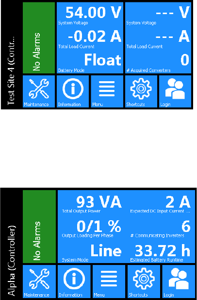
Cordex HP Controller Software Manual | 4 - Getting Started
Figure 19. Dashboard with Multi-system Panels
Figure 20. Dashboard Using Wide Data Panel View
To access the wide data layout, go to Controller > Shortcuts > Dashboard Config > LCD Dashboard
Option > Wide Data Panel. If there is more than one system on the controller. Switching to Wide Data
Panel from “Automatic” is a two-step process. Once Wide Data Panel is chosen, a specific system must
be selected so that the data values display for that specific system.
Language: Provides access to the Controller > Configure Controller > User Interface Preferences >
Language screen, where the language for the LCD can be changed to any of the available translations.
Page 44 0350058-J0 Rev AD

Cordex HP Controller Software Manual | 4 - Getting Started
Figure 21. Language
Browse USB: Provides access to an LCD-only function, which allows you to view the files on any USB
drive that may be attached to the controller. If a file is selected from this view, the LCD goes to the
available action screen for that file – for example, the LCD displays an upgrade screen if an application
file is chosen from the USB.
Note: When using a USB drive with the controller, use a v3.0 (or later) USB drive for best reliability.
Once inserted, it can take up to 20 seconds for the controller to recognize a USB drive.
Figure 22. Browse USB
Export Diag. Info.: Provides an option to export a Diagnostic Information Package containing important
logs and a controller clone to a USB. This information is needed for any support requests. For more
information on how to download, refer to the Exporting Diagnostic Information section of this manual.
0350058-J0 Rev AD Page 45

Cordex HP Controller Software Manual | 4 - Getting Started
Figure 23. Export Diagnostic Information
Backup: Provides access to an LCD-only function. Clicking this button, allows you to do a back-up of the
system. It backs up the application, as well as the config file. These backups are stored in a Cordex HP.
file system and are saved on a USB drive.
Note: For the backup to work properly, only one USB drive should be attached at backup time. If a
file named Cordex HP.Backup already exists in the root directory of the USB drive, it is overwritten with
the current backup.
Figure 24. Backup
Restore: Provides an opportunity to insert a USB and restore a previously saved backup file.
Clock: Provides a direct link to the Time and Date screen.
Speaker: Provides the ability to enable or disable the speaker.
Display: Provides the ability to re-calibrate the touchscreen.
Note: When recalibrating the touchscreen display, the final screen of the wizard will say: Press
the Enter key to accept the new settings. Press the Esc key to keep the old settings. Press the
touchscreen anywhere to accept the new settings. If using a keyboard, you have the option to press the
ESC key to keep the old settings.
Page 46 0350058-J0 Rev AD
Cordex HP Controller Software Manual | 4 - Getting Started
Reset: Provides a direct link to reset the controller.
4.3.4. Overview of the Web Interface
The dashboard is the default view displayed when you login to the controller via the web. It provides an
up-to-date overview of most critical information of your system. It displays controller information, a system
summary table, and the list of any active alarms.
The upper-left tile of the screen provides a color-coded live status view of these alarm notifications. The
upper-right tile provides a system status bar with detailed information about the system(s).
If there are active alarms, the Alarm Notification tile displays the last active alarm according to alarm
priority:
• Red for major or critical alarms
• Amber for minor alarms
• Blue for warnings
Clicking the Alarm tile takes you directly to the Active Alarms menu.
If there are no active alarms, a No Alarms message will be shown. In some situations, the controller will
provide hints as to certain behaviors of systems, or mis-configurations. If there are no alarms, one hint
may be displayed below the No Alarms message. Hints are explained in more detail in later sections.
The upper-right tile displays System Status Bar(s) which contains summary information for the
system(s). Clicking the system link at the top of the System Status Bar(s) takes you directly to the
System status screen.
The upper right-side of the of the web interface also provides the Login and Language drop down
menus. From the language drop-down menu you can change the language from English to other
languages as well as choose imperial or metric measurement units for the display.
0350058-J0 Rev AD Page 47

Cordex HP Controller Software Manual | 4 - Getting Started
Figure 25. Dashboard Overview on Web Interface
Login
Language
System Status Bar(s)
Alarm Notifications
Live DataTiles
Menus
Breadcrumbs
Commands
Tables
Under the Alarm Notification and the System Status Bar are the main menus for the controller:
Dashboard (Home), Controller, System, Modules, Alarms and Events, and Shelf Layout.
As you enter the menus, the interface provides a context sensitive breadcrumb trail at all levels so that
you can “see” where you are within the system and go back to any previous menu. The lower area of the
main dashboard contains system tables with detailed information about:
• Controller Status
• System(s)
• Active Alarms
You can work with the system directly from this area.
Page 48 0350058-J0 Rev AD

Cordex HP Controller Software Manual | 4 - Getting Started
Figure 26. Main Dashboard Tables
On each line of the table, the right-side displays an icon. There are three different types of icons.
Figure 27. Table Icons
The right-side of every table provides three types of icons.
Edit: provides a details field that allows you
to edit values and change parameters.
Help: provides a variety of information
which may include a description of the feature,
it's function and the typical default values.
Click to see more details: takes you into the menus
and provides more detailed information on the
specific line that was clicked
0350058-J0 Rev AD Page 49
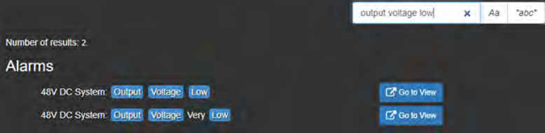
Cordex HP Controller Software Manual | 4 - Getting Started
4.3.4.1. Global Search- Web
Within the web interface, there is a search bar at the top-right of the screen. This search bar allows you to
quickly find the following information:
• Configuration
• Alarms
• Buttons
To search, enter terms into the search box. After the search returns a result, you can click on Go To View
to go to the view the status of that Configuration, Alarm, or Button. For Configuration, you can click Edit
to directly edit this value.
The following example illustrates the usage of the search bar to find the Output Voltage Low alarm for a
DC System.
Figure 28. Global Search Example
4.3.4.2. Paging, Sorting and Filtering - Web
Within the web interface there are three additional features that help you find information: paging, sorting
and filtering.
Paging: displays multiple page tabs on tables that have a large quantity of information. If there is too
much information for one table the table’s lower edge contains a list of numbers which allows you to scroll
through the information.
Sorting: provides a way to sort the table columns, either ascending or descending similar to any standard
spreadsheet program.
Filtering: provides an easy way to refine the information shown in a particular table.
The search bar on the upper-left side performs a search on each of the space-separated terms in all
columns of the table. The “Aa” toggle can be used to make the search case-sensitive, and the “Abc”
toggle can be used to only match whole words. For example, typing “dc system major” will display all
alarms of priority Major on the DC System.
The following example shows these features on the All Alarm Settings table.
Page 50 0350058-J0 Rev AD

Cordex HP Controller Software Manual | 4 - Getting Started
Figure 29. Web Interface Table Features
4.3.4.3. Controller Menu - Web
This section provides an overview of the Controller menu. The controller area has a total of four sub
menus in the form of live data tiles: Controller Status, Configure Controller, Inventory, and Advanced
Functions.
Figure 30. Controller Menu
Controller sub menus in the form of live data tiles
Controller Status: Provides the ability to reset the controller and view critical controller related
information.
Configure Controller: Provides access to configuration sub-menus including the following:
0350058-J0 Rev AD Page 51

Cordex HP Controller Software Manual | 4 - Getting Started
• Alarms and Alarm Summary Relays
• Controller Description
• Communications
• Speaker (if available)
• Time and Date
• Users and Security
• User Interface Preferences
Inventory: Provides a Inventory table displaying configurable list of systems as well as buttons to
manually create or remove them.
Figure 31. System Wizards
Advanced Functions: Provides sub menus for viewing details and working with advanced functionality,
including:
• Configuration File
• Controller Software Upgrade
• Licenses
• Factory Information
• User Alarms
• Custom Data
4.3.4.4. System Menu - Web
This section provides an overview of the System menu. Depending on your system configuration, the
power system menu area may have several sub menus in the form of live data tiles (e.g. a DC System
and a Converter System). If the controller is new, and a system hasn’t been created yet, the web page
displays the following information.
Page 52 0350058-J0 Rev AD

Cordex HP Controller Software Manual | 4 - Getting Started
Figure 32. Controller with No System Configured
If systems are already configured, they display under the Systems menu.
Figure 33. Systems Data Tiles
Most systems will have additional sub menus in the form of live data tiles such as: Status, Configure
System, and Inventory. Some systems will also have a System Functions sub menu as shown here.
Figure 34. System Menu
Status: Provides a view of the system’s general details.
0350058-J0 Rev AD Page 53
Cordex HP Controller Software Manual | 4 - Getting Started
Configure System: Provides system configuration, system properties and system alarms.
Inventory: Provides six sub menus to do add, remove or configure inventory times, e.g.:
• Rectifiers
• FXM HP
• Battery
• Loads
• Disconnects
• Shunts
• Other Transducers
System Functions: Provides sub menus to manage how the system operates, e.g.:
• Charging
• Temperature Compensation
• Equalize and Boost
• Battery Test
• Battery Runtime and Health
• Rectifier Control and Monitoring
• Power Save
4.3.4.5. Modules Menu - Web
This section provides an overview of the Modules menu.
The Modules menu has the following tables: All Modules, Firmware Upgrade, and Firmware Files.
Page 54 0350058-J0 Rev AD

Cordex HP Controller Software Manual | 4 - Getting Started
Figure 35. Modules Menu
All Modules: Provides a table to view or locate all modules.
Firmware Upgrade: Provides a table to start and monitor a firmware upgrade.
Firmware Files: Provides a table to view, upload or delete firmware files.
Note: Even if a system is configured to auto-assign devices, once a rectifier has been unassigned
from the system, it must be manually reassigned back into the system. This is necessary to avoid
unintentional auto-assignment. If a device is unassigned using the Forget button, then it will auto-assign
when discovered on the CAN bus.
4.3.4.6. Alarms Menu - Web
The alarms section has three sub menus: Active Alarms, Alarm Cut-Off and Global Alarm Settings,
and All Alarm Settings.
Figure 36. Alarms Menu
0350058-J0 Rev AD Page 55

Cordex HP Controller Software Manual | 4 - Getting Started
Active Alarms: Provides tables to view and configure Active Alarms as well as an Alarm Cut-Off
button.
Alarm Cut-Off and Global Alarm Settings: Provides alarm cut-off functionality, configuration and
settings for global alarm behavior.
All Alarm Settings: Provides a table to view and configure all possible alarms including relay mapping to
alarms.
4.3.4.7. Logs Menu - Web
The logs section has a total of four sub menus in the form of live data tiles: Events and Alerts, Battery,
Datalogs, and Performance. Every log can be exported to .csv files for further analysis.
Figure 37. Logs Menu
Events and Alerts: The Events table provides a list of system and controller events that record
configuration changes, alarms and general controller and system operation. The Module Alerts table
shows the module alert name and module serial number when a module reports an alert condition.
Battery: The battery log records the duration and change in capacity (Ah) for every charge and discharge
of a battery. If you have Battery Runtime and Heath enabled, the log will also record the change in State
of Charge (SOC) and State of Health (SOH).
Power Outage: The power outage log records the start time, end time and duration of each power
outage.
Datalogs: The datalog allows users to record measurements at set intervals over a period of time using
the CXC HP sensors and calculated values as inputs.
Performance: The performance log provides daily roll-ups with a minimum, maximum and average value
for key usage statistics. For power systems, that usually includes the input voltage and current and the
output voltage and current. For the controller, the CPU and memory usage are tracked.
4.3.4.8. Shelf Layout Menu - Web
The Shelf Layout page displays a virtual view of your shelf layout system. To display the physical
representation of a system, a device must provide the bay/shelf and slot ID information.
Page 56 0350058-J0 Rev AD

Cordex HP Controller Software Manual | 4 - Getting Started
Figure 38. Shelf Layout Menu
From the Shelf Layout. you can click on any of the devices to be taken to the device details page.
The following modules support the Shelf Layout function:
• Cordex HP 12kW 48Vdc
• LPS36
• eLimiter+
• AIM 2500
If all the devices in a system do not have Bay/Shelf/Slot ID information then the view will switch to a
simple table with each device on a separate row.
Refer to your device manual to determine whether your device(s) support this feature.
Configure Shelf Layout
The Shelf Layout page has a button called Configure Shelf Layout for DC Systems and Converter
Systems. If all the modules of your system have Bay/Shelf/Slot ID information, the button will appear on
top of the system’s shelf layout. Otherwise the button will appear on the simple table of modules.
To map your modules to the Shelf Layout:
1. Click on Configure Shelf Layout to launch the Configure Shelf Layout page
2. On the module you wish to map, press the Locate button under the Actions column. The physical
module will begin to blink.
3. On your physical layout, locate the blinking module and make a note of the slot position.
4. On the Shelf Layout page, drag the module from the System table to the appropriate shelf/slot
position on the layout grid.
0350058-J0 Rev AD Page 57

Cordex HP Controller Software Manual | 4 - Getting Started
5. To remove a module from the layout grid, press the red “X” icon. The module will return to the
system table.
6. Repeat the steps above until you have mapped all your modules.
7. After you have mapped all the modules, go to Shelf Layout on the main menu and you will see the
completed shelf layout grid.
If you click on a module in the layout, you will be taken to the details of the module. In the details page,
you will see that the Bay/Shelf/Slot ID information is set to where you dropped the module.
4.3.5. Overview of the In-Shelf Display
CXC HP in-shelf controllers have a small organic LED (OLED) display. This displays shows 30 characters
total (six characters wide, five lines high) and the controller has three navigation buttons and one reset
button.
In-Shelf Display: Screens
The in-shelf display has three main operating modes: dashboard, menu and screen saver. After 20
minutes with no activity, the in-shelf controller goes into screen saver mode and the display shuts off.
From screen saver mode, press any of the three navigation buttons to re-activate the screen and enter
dashboard mode.
In dashboard mode, the in-shelf display shows the key operating parameters of a system. For example,
output voltage and load current. If more than one system is defined, you can cycle between systems
using the Forward and Back buttons. With multiple systems, you can specify a default system, which is
then displayed first.
To set a default system, from the web interface, go to the Controller > Configure Controller > User
Interface Preferences > In-Shelf Controller Display Preferences table.
The following figure below shows examples of the OELD screens.
Page 58 0350058-J0 Rev AD

Cordex HP Controller Software Manual | 4 - Getting Started
Figure 39. In-Shelf Controller Dashboard Screens
A C - 1 2 0
1 2 0 . 1 V
7 8 7 2 V A
8 0 2 3 V A
7 9 0 2 V A
D C - - 4 8
5 4 . 0 9 V
1 0 3 . 1 A
F l o a t
D C - - 2 4
2 6 . 9 2 V
3 7 . 2 3 A
System
Output Type
AC or DC
Nominal
Output
Voltage
Output Voltage
Phase 1 Output Power
Phase 2 Output Power
Phase 3 Output Power
Output Voltage
Output Current
Output Voltage
Output Current
Battery Mode
In-Shelf Display: Menu
From the OLED dashboard, use the Select button to enter a menu. From the menu, the OLED display
lets you execute a set of commands much like the LCD screens on the CXC HP.
When you enter a menu, the top item is highlighted. To go to another menu scroll through using the
Forward and Back buttons. To execute a highlighted menu item, press the Select button.
To exit a menu and return to the main OLED dashboard, scroll to the Back command, and then press the
Select button. The figure below shows an example of the menu screen. The following table provides a full
list of menus available via the in-shelf display.
Figure 40. In-Shelf Controller Menu
M e n u
A L C O
R e s e t
I P v 4
I P v 6
A L C O
Table 1. In-Shelf Controller Full Menu
Menu Label Description
ALCO Perform the alarm cut-off command
Reset Perform a software reset of the controller
IPv4 Display the IPv4 address, subnet and gateway for this controller
IPv6 Display the IPv6 addresses assigned to this controller
AutoIP Set the IP to Automatic (obtained from DHCP server)
0350058-J0 Rev AD Page 59
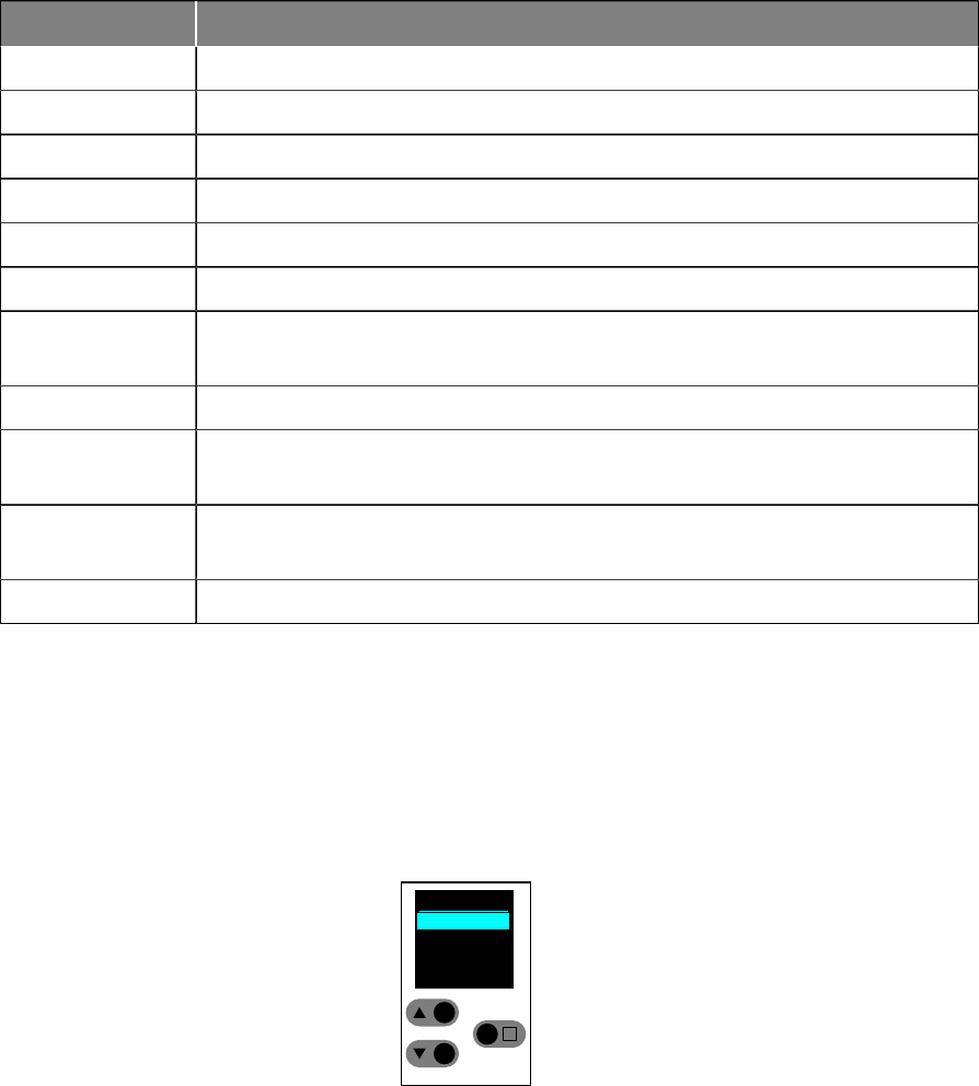
Cordex HP Controller Software Manual | 4 - Getting Started
Table 1. In-Shelf Controller Full Menu (continued)
Menu Label Description
RstIP Reset the IP to Static Default (IP: 10.10.10.201, Subnet: 255.255.255.0)
Port Displays the Port number for the controller
Backup Backup the controller application and configuration to a file on a USB device
Restore Restore the controller application and configuration from a file on a USB device
Upgra... Upgrade the controller application from a file on a USB device
OS Upg Upgrade the controller’s operating system from a file on a USB device
Info Display controller information including serial number, part number, software and hard-
ware version
Rotate Rotate the in-shelf controller display information by 90 degrees
Explnv Export all inventory to USB drive. This is a large file and may take a while to export. The
data can be used for analysis in a spreadsheet program.
RemCfg When Remote Configuration Lockout has been enabled, this menu allows the lockout to
be temporarily overridden for a pre-configured amount of time.
Back Exit the menu and return to the OLED dashboard
In-Shelf Controller: Buttons
The in-shelf controller can be mounted vertically or horizontally. The contents of the display can be
rotated, but the buttons cannot be rotated. The following figures show how the buttons are interpreted for
both mounting options.
Figure 41. In-Shelf Controller Buttons: Vertical Mount
M e n u
A L C O
R e s e t
I P v 4
I P v 6
A L C O
Back
Forward
Select
Page 60 0350058-J0 Rev AD

Cordex HP Controller Software Manual | 4 - Getting Started
Figure 42. In-Shelf Controller Buttons: Horizontal Mount
M e n u
A L C O
R e s e t
I P v 4
I P v 6
A L C O
Back Forward
Select
4.4. Email Notification
The CXC HP can be configured to send alarm summary emails. In this case the CXC HP is acting as a
Simple Mail Transfer Protocol (SMTP) client. This section of the manual describes the features of and
how to set up the CXC HP email client.
For email notifications in a different language, go to Controller > Configure Controller > User Interface
Preferences > LCD Preferences. Set the LCD Language to a preferred language.
Figure 43. Default Ports: SMTP Client and Server
A summary of alarm activities in the controller can be delivered using email. A period of monitoring time is
configured, and then all alarms within that period are reported.
This summary is designed to assist decision making when determining the urgency of any action required
to resolve issues that may occur in your system.
Table 2. Email Notification Features
Feature Description
HTML Based Emails HTML based emails provide better formatting features such as color
coding and table alignment.
Multi-level Security Different security levels are available and automatic detection is exe-
cuted to support the appropriate level. Direct SSL connection (default
port 486) is NOT currently supported.
0350058-J0 Rev AD Page 61

Cordex HP Controller Software Manual | 4 - Getting Started
Table 2. Email Notification Features (continued)
Feature Description
Encrypted SMTP Server Password The password used for authentication on the SMTP server is securely
encrypted.
Test Email Capability A test button is available to send a test email ensuring proper configu-
rations are set for email notifications to reach the appropriate monitors.
Public SMTP Server We currently support the following public server:
• Gmail – With less secured connection set in the Gmail account.
(OAuth2 protocol is not supported. Please refer to Google
developer site for more details. https://developers.google-
.com/identity/protocols/OAuth2)
Private SMTP Server The controller supports private servers with the following security set-
tings:
• TLS
• Clear text with authentication
• Clear text anonymous
Email Content
• Subject line with filterable text and alarm counts.
• Static title for filtering.
• Configurable name of the controller.
• Configurable location of the controller which provides a link to open Google Maps showing the
location of the controller (Internet connection required).
• Time and date of the notification.
• List of up to ten active alarms sorted by priority with an active alarm count indicator showing total
active alarms.
• List of up to ten cleared alarms sorted by priority with a cleared alarm count indicator showing total
cleared alarms.
How Email Notification Works
• An alarm activity is the main item that will trigger an email notification. To avoid overwhelming the
network, emails are only sent out at the configured interval set in the Email Configuration page.
• When alarm transitions occur (e.g., alarms activating or clearing) a timer starts from the first
transition. During this collection period, all alarm transitions are collected for reporting in the email
that is sent out at the end of the period. Continued transitions after the email is sent will start
another timer for the next email notification.
Page 62 0350058-J0 Rev AD

Cordex HP Controller Software Manual | 4 - Getting Started
• Active alarms are reported as a snap shot of all currently active alarms, regardless of when they
activated or if they were a part of a previous notification.
• All cleared alarms are collected based on the last occurrence within the collection period. This is to
avoid multiple entries of the same alarm in the case the alarm toggled multiple times.
Secured Email
Connection to a SMTP server defaults to TLS secured connection on port 587. Checks are done via the
controller and if TLS is not supported, proper degradation of security features is done in the following
sequence:
1. TLS handshake attempt.
2. Clear-text authentication with username and password.
3. Anonymous clear-text transmission with no authentication.
The checks are done by following SMTP protocol for SMTP server commands and responses. Please see
SMTP protocol standards for more details.
Table 3. Email Configuration
Configuration Description
Enable Email notification defaults to inactive. Enabling allows email notifica-
tions to go out when all configuration information is set correctly.
STMP Server Address A DNS name or an IP address will work in providing a target location of
the email server.
Port Default port is 587
Domain This is a DNS formatted string (words separated by '.') used for iden-
tifying the client to the SMTP server. Required for most public SMTP
servers like Google.
SMTP User Name The username used for authentication to the server to access SMTP
resources.
SMTP Password The password used for authentication to the server to access SMTP re-
sources. Set this value by using the Set SMTP Server Password but-
ton. You can clear the configured password by using the Clear Server
Password button.
From The From field is used as the source of the email and is usually the
same as the Username provided to authenticate the client to the SMTP
server. For example, Gmail requires this value to be the email address
of the account in use.
To The To field is for the destination or receiver of the email notification.
This field allows multiple email address entries separated by commas.
0350058-J0 Rev AD Page 63

Cordex HP Controller Software Manual | 4 - Getting Started
4.5. Setting up SNMP Communication
Simple Network Management Protocol (SNMP) is a standard protocol or language that Network
Management Systems (NMS or SNMP manager) use to control network devices and report information.
A typical SNMP system is often represented as one SNMP manager collecting data from several SNMP
agents or devices.
The CXC HP acts as an agent or device in an SNMP system. This section of the manual describes how
to add a new agent (the CXC HP) to an existing SNMP system. It does not cover how to set up an SNMP
manager nor does it explain how to correctly set up an SNMP system. Those topics are specific to the
SNMP management software chosen which will have its own documentation.
Figure 44. Default Ports: SNMP Manager and Agent
Ethernet
Network
SNMP
Manager
NMS
SNMP
Agent
Manager Receives Notifications
on UDP Port 162
Agent Receives Requests
on UDP Port 161
There are two main steps required to add a new agent to your SNMP system:
• Configure the agent with the IP address of your SNMP manager (tell the agent to send information
to the manager).
• Compile the agent's Management Information Bases (MIBs) into the manager (tell the manager
how to interpret information sent by the agent).
Configuring IP Address to Receive Notifications
Configuring an IP address for notifications is referred to as Subscribing to Notification Services. Up to
ten IP addresses can be configured. SNMP monitoring systems need to compile and install the ALPHA-
NOTIFICATION-MIB. Please refer to the user guide of the SNMP manager for this process.
Page 64 0350058-J0 Rev AD

Cordex HP Controller Software Manual | 4 - Getting Started
Figure 45. SNMP Destination Page:
Clicking one of the more details icons on the right-side of the row takes you to an edit page to configure
the appropriate fields.
Figure 46. Destination 1 More Information Page:
Clicking the edit icon on the IP address row allows you to insert an IP address of the monitoring
destination.
Note: For detailed information on using SNMP, see the SNMP Integrator Guide (0350099-J0) on the
Alpha website, www.alpha.ca.
4.6. Setting up Modbus Communication
The controller can act as a Modbus server (or slave or agent) in a Modbus system. This section of the
manual describes how to enable the Modbus server on the controller. It does not cover how to set up an
Modbus master (or client) nor does it explain how to correctly set up a Modbus monitoring system. Those
topics are specific to the Modbus master software chosen which will have its own documentation.
0350058-J0 Rev AD Page 65

Cordex HP Controller Software Manual | 4 - Getting Started
Figure 47. Default Ports: Modbus Client (Master) and Server (Slave)
Server Receives Requests
on
TC
P Port 502
Modbus
Server
Ethernet
Network
Modbus
Client
To setup Modbus TCP/IP on the controller, you need to enable the Modbus server via the web interface.
1. Go to Controller > Configure Controller > Communications > Modbus.
2. In the Configuration table, click the edit icon and select Enable from the drop-down menu.
3. Click the edit icon on the Byte Order line, and then select the byte order.
4. Device IDs are normally left as the default values.
Figure 48. Enabling Modbus on the Controller
Note: For detailed information on using Modbus, download the Modbus Integrator Guide (0350114-
J0) on the Alpha website, www.alpha.ca.
Page 66 0350058-J0 Rev AD

5. DC Power Systems
This section provides a brief overview of the components and functions within a typical DC power system.
A basic power system usually consists of rectifiers and batteries, but can also include other components.
5.1. Guidelines for Commissioning the DC System
The following section contains basic guidelines for commissioning a DC power system. Overall system
commissioning consists of four parts: power system inspection, battery inspection, commissioning the
system and testing the system. Commissioning should only be conducted by a qualified technician. For
more detailed information refer to the relevant system manual for your specific system.
Perform an inspection of the power system to confirm that the mechanical and electrical requirements and
parameters are within specification. Pay special attention to the battery to ensure it is installed safely and
correctly, and that the battery terminals are torqued to specification.
1. Make sure all power to the system is off.
Are all batteries disconnected, rectifier modules are removed, fuses pulled and circuit breakers
turned off?
2. Make sure the battery polarity is correct. Use a voltmeter if necessary to confirm.
3. Install one rectifier.
4. Turn on the AC to the rectifier and allow it to start up.
Verify that the system starts up, and the controller turns on. Did the rectifier turn on? AC and DC
lights on?
Note: At no load and batteries disconnected, rectifier may have a fail alert. This should go
away when load is connected.
5. Confirm the battery settings on the controller: capacity, charge limit, the Peukert exponent, etc. If
there is no means of disconnecting the battery, then the rectifier output voltage should be reduced
by using the controller to match the rectifier voltage to the battery voltage to avoid sparks.
6. Check that the battery polarity is correct and turn on the breakers, fuse or circuit breakers for the
batteries.
7. Follow the initial battery charge procedure as indicated in the manufacturer’s instructions.
The controller and rectifiers are operating normally. There may or may not be active alarms depending on
system configuration.
Perform commissioning tests to confirm that the system is operating properly. Specific tests to perform will
depend on the system configuration but may include:
• Correct AC input voltage and DC output voltage
• Battery test
• Relay test
• Battery disconnect operation
0350058-J0 Rev AD Page 67

Cordex HP Controller Software Manual | 5 - DC Power Systems
• Alarm test
5.1.1. The Battery Mode
The Battery Mode value, as shown in top section of the web page or in the system Status page,
indicates the state of the battery in the system.
In a system with a fully charged battery, the Battery Mode will be Float which indicates the battery is
floating.
In a system that is charging, the Battery Mode will be Charging. The adjacent value either show Bulk
(battery is charging at constant current) or Absorption (battery is in the absorption phase of charging).
In a system that is discharging the Battery Mode will either be Discharging (AC mains has failed) or
Test Discharging (battery test in progress).
Figure 49. Battery Mode
The Battery Mode may also be No Battery (no battery in the system), Disconnected (battery appears
disconnected) or Unknown. When it is Unknown then the controller is busy trying to determine the state
of the battery. If this value persists for more then a minute or so, it may indicate that one or more of the
following may not be properly configured:
• load current
• battery current
• battery capacity
• system voltage
• battery voltage (it is recommend that system voltage and battery voltage to be configured to read
the same)
5.2. DC System Functions
5.2.1. Modules, Inventory and System Functions
To set up a system on the CXC HP, you need to work with modules, inventory and system functions. This
section explains these terms which will help you to navigate the CXC HP menu and answer questions
such as:
• Why are rectifiers in both the Modules, and in the Inventory menus, but ADIOs are only in the
Modules menu?
• Why is temperature compensation in the System Functions menu, and not under the Inventory >
Battery menu?
Page 68 0350058-J0 Rev AD
Cordex HP Controller Software Manual | 5 - DC Power Systems
Modules
A module is a device that communicates information. Most modules in a CXC HP system will be CAN
devices such as rectifiers, converters, inverters and ADIOs. Future releases, may have modules such as
Ethernet and USB-serial connected modules.
Since the CXC HP can communicate with modules, each module in the system should also have a
Communications Lost alarm. Most modules are replaceable, because of this there are functions within
the system to remove old modules and create new ones. Some modules also have the ability to download
reports and diagnostic information via the CXC HP.
Inventory
An inventory item is an item that is directly involved in the flow of power through the system. For example,
a rectifier is an inventory item but a controller or an ADIO is not. Other examples of system inventory are:
AC source, rectifier, load, battery, disconnect, shunt, DCCT, breaker and power meter. Setting up the
inventory of a system focuses on the monitoring, not the control of the system.
You can set monitoring in one of three ways:
1. If the inventory item is also a module, you can communicate with it directly, such as with rectifiers.
2. If the inventory can be measured or controlled via an ADIO, then you can map the inventory to
read data through the ADIO, such as with shunts, batteries, current transducers and disconnects.
3. If the inventory item’s values can be inferred through a calculation, then you can map the inventory
to use that calculation such as with AC sources and DC loads.
System Functions
System functions are the major features of the system. Some examples are:
• Battery charging
• Battery runtime estimation
• Charge current control
• Voltage regulation
• Temperature compensation
Once the inventory is in place to monitor the system, you can configure and test the system functions to
ensure that the system is working as intended.
5.2.2. Mixed Rectifier System
You can add any rectifier to the DC system that has the appropriate DC bus voltage. Some of the System
Functions assume that the rectifiers controlled, and the batteries managed are the only source of power
on the DC bus. Those System Functions work best with either a single rectifier model or models that
have been designed to work together such as, the Cordex 1.8kW and the Cordex HP 2.0kW, or the
Cordex 3.6kW and the Cordex HP 4.0kW.
Mixing of other rectifier types is not recommended. If you need to mix other sizes and types of rectifiers
you many need to turn off some of the System Functions for the DC System. See your system manual
0350058-J0 Rev AD Page 69

Cordex HP Controller Software Manual | 5 - DC Power Systems
or contact Alpha Technical Support if you encounter this situation and do not have instructions on how to
set up the System Functions.
5.2.3. Battery Charging
The CXC HP applies a typical three-stage charging cycle including Bulk Charging, Absorption Charging
and Conditioning which is sometimes called float charging.
Figure 50. Three-Stage Charging Cycle
Bulk Charging
After the bulk charging stage, the battery should be in a 70%-90% state of charge. In the Bulk Charging
menu, you can enable/disable charge current control and set the charge current limit (C/X) in hours.
CAUTION: If you do not set a charge current limit, the battery may be charged at a much higher rate
than is recommended by the battery manufacturer.
Absorption Charging
After the absorption charging stage, the battery should be in a 95%-98% state of charge. In the
Absorption Charging menu, you have the option to charge the battery at a voltage higher than the float
voltage. The higher voltage is used to speed up the absorption charging stage after a prolonged AC
power failure.
Conditioning - Float
The conditioning or float charging stage brings the batteries to 100% state of charge and maintains it
there. When the system is in the conditioning stage it is usually at the Float Voltage. When the system
Page 70 0350058-J0 Rev AD

Cordex HP Controller Software Manual | 5 - DC Power Systems
is in conditioning-float, a higher Equalize Voltage or Boost Voltage can be applied from the System >
System Functions > Equalize and Boost menu.
Conditioning - Equalization
When a string of battery cells or blocks are charged, a single charge current is applied on the group.
If the voltages of the cells or blocks begin to differ, the charge imbalance can lead to battery failure.
Applying a higher Equalize Voltage to a fully charged battery string subjects the stronger cells or blocks
to overcharge but this also allows the weaker cells or blocks to regain their full charge. When the voltage
is returned to the Float Voltage, the stronger cells shed their overcharge and the battery string should be
more balanced or equalized.
Applying an Equalize Voltage (an overcharge) to a fully charged battery can also be used to reverse
sulfation.
CAUTION: Applying an overcharge to a battery string also has negative effects on the batteries. See
the battery manufacturer’s guide to determine whether an equalization voltage should be used at all. If
so, what the voltage and the duration should be, and how frequently an equalization charge should be
applied.
Conditioning - Boost
The purpose of boost is similar to equalize - to equalize cells or reverse sulfation. Boost voltage is usually
a higher voltage than equalize. In fact it can be too high for the load and therefore require the presence of
dropping diodes to be switched into the circuit between the rectifiers and the load to prevent damage to
the load. Before boost can be activated, the dropping diodes must be switched into the circuit.
5.2.4. Battery Temperature Compensation
Temperature compensation (Temp Comp) is used to prolong battery life and help prevent thermal
runaway. When battery temperature compensation is enabled, the controller uses the battery temperature
to calculate an offset which is applied to the battery voltage.
A typical temperature compensation curve for a 48V battery system is shown in the following figure.
0350058-J0 Rev AD Page 71

Cordex HP Controller Software Manual | 5 - DC Power Systems
Figure 51. Temperature Compensation Voltage Graph
56
55
54
53
52
-5
0
5
10 15 20 25
30 35
40
45
50
55
Temperature Compensation
Battery Voltage Curve
Voltage (V)
Temperature (°C)
Upper Temperature Breakpoint
Lower Temperature Breakpoint
Battery performance and life expectancy are directly related to the battery ambient temperature. The
optimum operating temperature for battery operation is typically 25°C (77°F). Above this temperature
battery life may be reduced and below this temperature battery performance may be reduced.
Thermal runaway occurs if the internal temperature rises due to overcharge, high ambient temperature or
internal fault. Temp Comp automatically adjusts the float voltage as the battery temperature changes to
protect the battery from thermal runaway.
The Temp Comp function adjusts the system voltage every two seconds, as the temperature changes,
and provides for a maximum voltage change of 0.1V over this interval. Temp Comp occurs at standard
rates commonly referred to as slope-compensation settings.
The slope of the Temp Comp curve in either mV/°F/Cell or mV/°C/Cell can be set via the System >
System Functions > Temperature Compensation. The value is set based on the battery manufacturer’s
information.
Since a battery can have multiple temperature sensors, temperature compensation uses the average of
the temperature readings to determine the battery temperature on which to adjust the battery voltage.
The average is used as long as all the temperature readings are within 5°C (9°F) of each other. When a
temperature reading rises, perhaps due to local heating or thermal runaway, and reaches a point when
the highest temperature reading is 5°C greater than the lowest temperature reading, then temperature
compensation will use the highest temperature reading to determine the compensated battery voltage.
This will result in a lower battery voltage and reduce the risk of thermal runaway.
If one or more battery temperature probes appear to be disconnected or broken, then the Temp Comp
function calculates the enabled setpoints as if the temperature reached the Upper Temperature
Breakpoint. This is the safest option in case the failed sensor happened to be the one with the highest
temperature reading.
5.2.5. Battery Runtime and Health Estimation
If Battery Estimation is enabled, the controller calculates an Estimated State of Charge (SOC), and
an Estimated Battery Runtime remaining (RTR) at all times. It is not always practical to estimate these
Page 72 0350058-J0 Rev AD

Cordex HP Controller Software Manual | 5 - DC Power Systems
values. For example, if the system goes into a charging stage immediately after a restart, there is no way
to estimate the SOC or RTR.
The accuracy of the estimated battery health improves as the battery undergoes more discharge cycles
and it also improves with deeper discharges.
If a battery discharge occurs that goes below an SOC value of 80%, then the Battery Runtime and
Health Estimation function creates a Last Battery Discharge Summary, a Last Battery Recharge
Summary and recalculates the Estimated Battery Health. If estimated battery health is less than 80%
then that battery is normally due to be replaced.
5.2.6. Low Voltage Disconnect Operation
Whenever the system parameters requires the LVD to be activated, a 60-second countdown and audible
warning begins. When the countdown reaches zero, the LVD is activated.
During the countdown, a command in the disconnect menu can be pressed to inhibit LVD activation.
When the disconnect first changes to Pending, every user logged into the system will receive notification
that the disconnect is about to activate, and the option to inhibit it. To release the inhibit, you must activate
the release command for each LVD.
Figure 52. Inhibit Disconnect
There are two types of disconnects: “legacy” disconnect and a general purpose disconnect.
Legacy Disconnect
The legacy disconnect is the first disconnect available on the controller. It offers the ability to disconnect
based on voltage, time elapsed since AC fail, and the state of charge of the battery.
General Purpose Disconnect
The general purpose disconnect is best suited for use as a load shedding disconnect. It can be configured
to disconnect based on voltage, or up to three customizable disconnect conditions. There are three
customizable reconnect conditions in addition to the usual voltage reconnect threshold.
0350058-J0 Rev AD Page 73
Cordex HP Controller Software Manual | 5 - DC Power Systems
When using the optional disconnect, note the following conditions:
• the voltage must be less than the disconnect threshold OR
• one or more optional disconnect conditions are true AND
• all optional reconnects must be unknown or false
• if the option to disallow disconnect during battery test is true and battery test is active, the
disconnect will not activate until battery test is no longer active or option is disabled.
When using the optional reconnect, note the following conditions:
• the voltage must be greater than the connect threshold OR
• one or more optional reconnect conditions are true AND
• all optional disconnect conditions must be unknown or false
• if the option to require AC for reconnect is enabled and AC input is not present no reconnect will
occur until AC returns or this option is disabled.
To better support use as a load shedding disconnect there are three configuration parameters that may be
used to further customize the behavior:
1. Allow Disconnect During Battery Test - by default this is set to No but may be set to Yes.
Example: using the battery test to observe and measure the runtime available to critical loads after
less important loads are disconnected.
2. Require AC Info For Reconnect - by default this is set to Yes but may be set to No. Example: if
there are additional DC sources (like solar panels or a DC generator) on the voltage bus that are
capable of supporting the loads even when AC is lost.
3. Required Time to Stay Disconnected- by default this is set to 0 seconds. It may be set to a non-
zero number in to ensure that a load is fully powered off before reconnecting. Some loads may not
start up correctly unless they are fully powered off first.
5.2.7. Battery Test
Battery test mode is used to update the Estimated State of Health of a lead acid battery.
Definitions
• Battery Test Termination Voltage — The voltage threshold at which the test normally ends.
• Battery Test Timeout — The maximum time the test can run before it is stopped.
• Battery Test Termination on SOC— Enable or disable the Battery Test Termination SOC threshold
to terminate a battery test.
• Battery Test Termination SOC — The State of Charge (SOC) threshold at which the test normally
ends.
• Battery Test Alarm — The battery test is active.
Page 74 0350058-J0 Rev AD
Cordex HP Controller Software Manual | 5 - DC Power Systems
Using the Test Discharge (TD) Mode
If the test is started when the battery is fully charged, the results of the battery capacity estimate
will be more accurate. Use charge current control to limit the battery recharge current to the battery
manufacturer’s specified maximum value.
During a test, the Estimated State of Charge and Estimated Battery Runtime hours can be viewed
via the System > Status menu or the System > System Functions > Battery Runtime and Health
Estimation menu.
Test Discharge Initiation
When the test begins, an entry is made in the event log. If the Battery Test Alarm has been enabled, it
provides a warning to indicate that a battery test is in progress. The output voltage of the rectifiers is set
to the Battery Test Termination Voltage to allow the battery to discharge. Battery Mode changes to Test
Discharge when a battery test is started.
Test discharge mode runs for the period set as timeout or until the battery test termination voltage is
reached or the battery test termination SOC is reached (if enabled).
The rectifiers are periodically scanned to ensure that they do not begin sourcing current. If so then the
test is stopped and the battery is recharged.
The rectifier float is reset to the setting that is stored in the system controller. When the system voltage
reaches the end (termination) voltage or a timeout occurs, the system controller will command the
rectifiers to turn on and enter FL mode.
Activity During Test Discharge Mode
Temperature compensation features are suspended during a battery test. When the battery is
discharging, the battery test alarm is active. Battery state of health estimation begins at 3% of DOD, but is
not displayed unless DOD > 20%; the point at which reasonable accuracy can be assured.
AC Failure During Test Discharge Mode
If the AC fails during a battery test, the test is aborted. This places the rectifiers into a state that enables
them to resume providing power to the load when AC returns. If the runtime is being displayed, it
continues to update.
Addition of Rectifiers During Test Discharge Mode
If rectifiers are added to the system when a battery test is active, they are placed into the same state as
the current system rectifiers. They are either: placed into battery test state or set to the same voltage as
rectifiers already in the system.
Conditions to Watch for During Test Discharge Mode
If the voltage drops below 46V before or when 3% depth of discharge is reached, the test is aborted
and the battery health is set to 0% (resulting in a Battery Health Low alarm). This provides an indication
that the battery is very weak. Battery state of health must be manually reset to 100% before the next
battery test is started, so that the battery monitor can properly estimate the battery health. If rectifiers are
sourcing current during the test, and the battery ceases discharging, the test is aborted.
0350058-J0 Rev AD Page 75
Cordex HP Controller Software Manual | 5 - DC Power Systems
Canceling Test Discharge Mode
Test Discharge mode can be canceled by either changing the mode to Float or stopping the test manually.
To stop the battery test manually go to System > DC System > System Functions > Battery Test and
press the Stop Manual Battery Test button.
Battery Discharge Test Completion
Once the battery begins to charge, the recharge cycle begins. Live battery recharge information is
available via the System > DC System > System Functions > Battery Runtime and Health Estimation
menu. The test is considered complete once the battery begins to charge. This is due to either, the test
ending from timeout, the system reaching the termination voltage or from an abort condition.
5.2.8. Power Save
When using Power Save Alpha recommends the following:
• That the Power Save feature only be used on systems with a battery.
• If a system supports 120-240Vac input operation and if operating at less than 208Vac - do not use
Power Save.
• The current and power capacity settings in Rectifiers > Configuration menu should be set to
100% when using Power Save.
The Power Save feature is designed to improve the efficiency of the system, by optimizing the output
power of the rectifiers. Rectifiers that are either loaded too light or too heavy generally have lower
efficiency.
Power Save analyzes the system power requirements, as well as available rectifier capacity, determining
the optimum loading. Based on the system information the controller then takes rectifiers into or out of
standby to achieve maximum rectifier efficiency. Rectifiers in standby do not supply to the load or to
battery charging. Power Save periodically cycles these rectifiers to ensure they contribute evenly to
supplying the load. This balances rectifier operation and maximizes rectifier lifetime.
When active, Power Save relies on the battery to briefly take up some of the load current during
operation. If there are modules in standby and the load increases, rectifiers supplying power will
momentarily have reduced capacity to supply the load. At that point the battery supplies the extra capacity
required. Power Save detects this and will bring one or more rectifiers out of standby so that the load is
fully supplied by the rectifiers.
Power Save has three main tables, Configuration, Status, and Modules tables. The Status table has
a Test Rotation Now button which can be used to immediately advance the rotation of the rectifiers.
Regularly scheduled rotation will still occurs according to the Module Rotates In time settings.
To view these tables go to: System > DC System > System Functions > Power Save.
Configuration Table
The Configuration table has the following fields:
Enable/disable: to set up Power Save on a system.
Page 76 0350058-J0 Rev AD
Cordex HP Controller Software Manual | 5 - DC Power Systems
Module Power for Maximum Efficiency: Provides a percentage at which the module should be loaded
to achieve maximum efficiency. Power Save works to get as close to this value as possible. Refer to the
module’s installation manual to get information for best performance. If you don’t have this information,
use the default value based on the rectifiers used.
Rotation Period: Provides the rate of module rotation The Rotate One Module Every value is a length
of time in days. After the configured number of days, the module that has been in standby longest will be
turned on, the module that has been on the longest will be turned off. Module rotation occurs at 3am.
Status Table
The Status table displays which values Power Save calculates. These include the following fields:
Power Save: Provides the general status which may be active, disabled, insufficient redundancy or
invalid data suspended. Power Save cannot operate if in a battery test, if AC has failed or if any required
data is unknown.
Average Power: Provides the average module output power computed for the system. Power Save
will try to get this value as close as possible to the Module Power for Maximum Efficiency (set in the
Configuration table). For example: if the efficiency target is 80%, and the average power is 72% and
turning off a rectifier would make the average power 83%, then Power Save will turn off a rectifier to get
closer to the efficiency target.
Module Rotates In: Provides how many hours left until the next module rotation (always occurs at 3am).
Estimated Time to Rotate All Modules: Provides the estimated number of days until all modules in the
system will be rotated. This value changes depending on number of rectifiers and rotation period.
Estimated Required Capacity: Provides the capacity required to supply the load and charge the battery.
For example, if your load is 100A and your battery charge current limit is 10A, this value would be 110A.
Estimated Available Capacity: Provides the estimated available capacity of all modules that are
Supplying Power (modules In Standby are not included).
Estimated Redundant Capacity: Provides the estimated extra capacity of all modules that are supplying
power in the system. In a system operating in Float mode, some modules are In Standby, and some
are Supplying Power. The modules Supplying Power may be loaded at 80%. The remaining 20% is
considered redundant capacity. This represents rectifier capacity that is immediately available should
a rectifier fail. This number can be increased by lowering the Module Power for Maximum Efficiency
to cause more rectifiers to turn on – it is up to the user to balance the requirement for redundancy vs
operating efficiency.
Modules Table
The Modules table displays the Power Save status of all the modules in the system including: serial
number, mode, and Hours Supplying Power, In Standby.
Hours Supplying Power and Hours In Standby is the time a rectifier spent in those modes.
5.3. Creating a DC System Manually
On a CXC HP controller, if there is no power system defined, you can create the inventory items needed
to monitor and control a DC power system. There are four steps to creating a new DC System.
0350058-J0 Rev AD Page 77

Cordex HP Controller Software Manual | 5 - DC Power Systems
1. Verify that the ADIO sensors you are using to monitor the system are working correctly, and
document the purpose of each sensor and relay used.
2. Create the DC system and other inventory items, and then configure the inventory to use the ADIO
sensors to monitor the system.
3. Configure each of the system functions to correctly control the DC system and manage the battery.
4. Adjust thresholds, enable/disable alarms and set up any remote alarm reporting using alarm relays
and/or SNMP notifications.
This section of the manual provides the first steps of how to set up a 48V DC system. For this example,
the system is set up as shown in the following figure.
Figure 53. Example of a DC System
CXC HP
ADIO
AC Source
Rectifiers
(Energy Conversion)
DC Load
Battery LVD
Battery Shunt
Battery
(Energy Storage)
CAN Bus
DC Bus
Ethernet
5.3.1. Quick Reference for Configuring a DC System
The following figure shows the key configuration settings for a DC system that should be set or checked
so that the system operates correctly.
There are many optional and alarm reporting settings that can also be configured.
Page 78 0350058-J0 Rev AD

Cordex HP Controller Software Manual | 5 - DC Power Systems
Figure 54. Quick Reference for Configuring a DC System
Controller > Inventory
Create DC System
System > DC System >
Configure System
[System Voltage Source]
Float Voltage = 54V
Rectifier Assignment Rule
= Automatic
System > DC System >
Inventory
> Battery Subsystem
> Battery String
[Battery Voltage Source]
[Battery Current Source]
[Battery Temperature Source]
Capacity Rating = 50 A-h
Peukert Exponent = 1.15
Name = Alphacell 85GXL-HP
Description = Install May 2013
System > DC System >
Inventory
> Loads > Load
[Load Voltage Source]
[Load Current Source]
System > DC System >
Inventory
> Rectifiers >
Configuration
Note: The defaults are fine for
this example
System > DC System >
System Functions
> Charging >
Bulk Charging
Charge Current Control = Enabled
Charge Current Limit (C/X) = 10
System > DC System >
System Functions
> Charging >
Absorption Charging
Auto Absorption Charging = Enabled
System > DC System >
System Functions
>
Temperature Compensation
Temp Comp in Float = Enabled
Temp Comp in Equalize = Enabled
Temp Comp in Absorption = Enabled
System > DC System >
System Functions
>
Battery Runtime and Health
Battery Estimation = Enabled
Load Model = Resistive
[Battery LVD]
System > DC System >
System Functions
>
Rectifier Control and Monitoring
Regulation = Enabled
Loadsharing = Enabled
System > DC System >
Inventory
> Disconnects >
Disconnect
[Relay]
Disconnect Threshold = 42V
Connect Threshold = 50V
Name = Battery Disconnect
System > DC System >
Inventory
> Shunts > Shunt
[Shunt Current Source]
Range in Amps = 800A
Range in Millivolts = 100mV
Name = Battery Shunt
Modules
> ADIOs > L-ADIO
V1 > Name = Bus Voltage
I1 > Name = Battery Current
T1 > Name = Battery Temp
K1 > Name = LVBD Relay
K10 > Name = Minor Alarm
K11 > Name = Major Alarm
K12 > Name = Critical Alarm
DC System Calculated Values
Total Output Current
Total Output Current - Battery Current
Total Output Current - Load Current
5.3.2. Creating a DC System
There is no DC power system on a brand new CXC HP controller. Creating a DC system is done using
the Create System wizard. In the current release, only a single DC system is supported, so if a system
already exists on the controller, the option to create a new DC system will not be available.
You can also import a configuration file containing a DC system from another controller.
A new power system can be created via the Controller menu from either the LCD touchscreen or the
web. Both have wizard assistance to help step you through the process to create the new system. You
0350058-J0 Rev AD Page 79

Cordex HP Controller Software Manual | 5 - DC Power Systems
can create either a 48V system or a 24V system. Once the system is created, an associated load, battery,
disconnect, and shunt is also created.
The DC power system will also be created with a reasonable set of defaults and associated alarms.
The only value which is mandatory to configure after system creation, is the System Voltage Source,
which can be set to any voltage input. It is recommended that this be set to the same input as the Battery
Voltage input. All other items, such as Name, Description, System Number, and Serial Number, are
optional and can be used to describe and organize your system.
The Rectifier Assignment Rule setting controls how newly discovered rectifiers are treated. The default
setting, Manual, means that new rectifiers will be grouped into Unassigned Modules, and then can be
manually added to the system. Alternatively, you can choose Automatic, which automatically adds new
rectifiers to the system. This is usually the preferred setting.
You can configure the alarms associated with the system. You can enable or disable the alarms, change
the priority, map relays to the alarms, and where applicable, modify the thresholds.
To create a DC system:
1. Go to Controller > Inventory and use the Create DC System wizard.
2. From the results page, click the Configure DC System wizard to be guided through system
configuration or follow the instructions that follow.
Page 80 0350058-J0 Rev AD

Cordex HP Controller Software Manual | 5 - DC Power Systems
3. Once configured, the Results page will give additional guidance on next steps to take.
Figure 55. Configure DC System Results Page
On the Results page the wizard provides information on what else needs to be done to ensure the
system functions as expected. Any lines coded blue denote action that must be taken, such as in the
above example, the Configure Shunt and Disconnect buttons. The gray coded lines indicate actions
recommended, such as in the above example, the Confirm Load and Battery String buttons. If the item
was configured correctly it will display with the line green, meaning no action is required.
0350058-J0 Rev AD Page 81

Cordex HP Controller Software Manual | 5 - DC Power Systems
5.3.2.1. Creating a System from a Configuration File
A system can be created by importing from a configuration file. See the “Importing a System” section to
do this.
5.3.3. Configure the Basic DC System Settings
The Configure system page has three tables (Configuration, System Properties, and Alarms) with some
basic settings that must be configured.
From the main dashboard:
1. Go to System > Configure System.
2. In the Configuration table to do the following:
a. Set the system name, description, number and serial number.
b. Set the float voltage setting. This is the desired output voltage of the rectifiers when the
system is in float mode.
c. Set the system voltage source, which is the voltage used to control the system. This is the
input of the ADIO that measures system output voltage, and is usually the same input as the
battery voltage.
3. In the System Properties table, change the Rectifier Assignment Rule to Automatic which
enables the controller to automatically assign rectifiers to this system. Only rectifiers of the type as
shown in the Rectifier Type field will be added to the system.
4. In the Alarms table, configure the alarms.
5.3.4. Configure Dynamic Thresholds for Output Voltage Alarms
Both the High and Low Output Voltage alarms can use a dynamically adjusted threshold. This Adjusted
Limit is calculated by adding the difference between the Voltage Regulation Setpoint and the Float
Voltage to the configured Limit. To use Output Voltage Alarm:
1. Go to System > DC System > Configure System.
2. In the Alarms table, click more details for the Output Voltage alarm to configure.
3. Use the drop-down menu to set the Absolute or Adjusted field to Adjusted.
5.3.5. Configure the Rectifiers
These are settings that include start delay, safe mode voltage or over-voltage protection threshold.
Note: The Safe Voltage is the voltage that the rectifiers default to if they lose communication with
the controller. This feature has a time delay that varies according to rectifier. Most rectifiers revert to Safe
Mode after five minutes. Check your rectifier manual for a list of the default parameters.
Rectifier output voltage is configured from the System > DC System > Configure System menu.
To configure the rectifiers:
Page 82 0350058-J0 Rev AD

Cordex HP Controller Software Manual | 5 - DC Power Systems
1. Go to System > DC System > Inventory > Rectifiers > Configuration.
2. Set up your rectifier group configuration settings. These include, start delay, safe mode voltage or
over-voltage protection threshold.
You can configure the group settings, using information in the following table.
5.3.5.1. Rectifier Configuration Guidelines
The following are guidelines for setting rectifier configuration. Some or all may apply.
Over Voltage Protection
Threshold
Set this value as far above equalize voltage or boost voltage as needed. For a
48V system, the usual value is 60V. The actual upper limit of this setting depends
on the rectifier model. If the Rectifier Configuration Error alarm is active, it usual-
ly means the OVP threshold is too high or too close to the equalize, boost or float
voltage setting. It is necessary to have at least 1V (for 48V system) difference be-
tween float, equalize and OVP settings.
System Start Delay Set this value to delay the start up of all rectifiers when AC returns to give other
AC equipment on site a chance to start up first.
Module Start Delay Set this value to apply a staggered start delay to individual rectifiers. This helps
limit AC inrush current and gives the controller time to engage charge current con-
trol, if enabled, to prevent a battery breaker or fuse from opening. Each rectifier is
assigned a module start delay that is a multiple of the configuration value. If the
value exceeds 250s, the value starts again at the lowest multiple. For example,
if the module start delay is 60s and there are 8 rectifiers in the system, the start
delays assigned to the rectifiers will be: 1s, 60s, 120s, 180s, 240s, 1s, 60s, 120s.
This means that three rectifiers will be assigned the same 1s, 60s, and 120s de-
lays.
Current Limit/Power
Limit
Set one of these values (not both) to limit the output current of the rectifier. This is
normally only done if the site has undersized AC breakers or is running on an un-
dersized AC generator. These values must only be set while in float mode. Setting
them when the battery is bulk charging may result in too much current to the bat-
tery.
Fast Soft Start Set this to enabled if the system has no batteries and the load does not turn on
when AC returns.
CL/PL alert This is usually disabled when the system has batteries to avoid a current limit or
power limit alarm during battery charging.
Ramp Test This is normally enabled to detect if a rectifier has been disconnected from the
load. When enabled and if the rectifier is sourcing less than 2.5% of it’s maximum
current, the rectifier will briefly raise it’s output voltage by 0.5V (for a 48V system)
once per minute. If the rectifier cannot source at least 2.5% of it’s maximum cur-
rent, the ramp test will fail and a Rectifier Fail alarm will activate.
0350058-J0 Rev AD Page 83

Cordex HP Controller Software Manual | 5 - DC Power Systems
5.3.6. Configure the Shunts
By default the system has one shunt. You may add or remove shunts as needed.
To configure a shunt you need an ADIO with current inputs. The shunt will map the current inputs from the
ADIO to the Load Current Source field of the Load Configuration table or the Battery Current Source
field of the Battery Configuration table.
To configure a shunt:
1. Go to System > DC System > Inventory > Shunts. You will see a list of shunts in the system. Add
or remove shunts from this page.
2. Click the more details icon for the shunt you want to configure.
3. In the Configuration table, assign the shunt a name and description. Alpha recommends that you
assign the shunt a name that represents the actual shunt. For example you might name it Battery
Shunt.
4. Select the Shunt Current Source. This is the current input on an ADIO that takes a voltage
reading across the shunt.
5. Enter the Range in Amps for the shunt.
6. Enter the Range in Millivolts for the shunt.
7. Enter the Offset Calibration for the shunt if the shunt reading error is too high.
5.3.7. Configure the Loads
By default the system has one load. You may add or remove loads as needed.
To configure each load:
1. Go to System > DC System > Inventory > Loads. You will see a list of loads in the system. Add
or remove loads from this screen.
2. Click the more details icon for the load you want to configure.
3. In the Configuration table, assign the load a name and a description. Alpha recommends that you
assign the load a name that represents the actual load.
4. Select the Load Voltage Source. This is the voltage input on an ADIO that takes a voltage reading
near the load.
Note: If you do not have this connected, you can select the input that reads the battery voltage
or system voltage.
5. Select the Load Current Source. This is the shunt input that reads the load current. If you have a
real shunt reading for the load current, then select the shunt from the drop-down menu. If you don't
see the shunt you want, then create it.
If you do not have a shunt for reading the load current, then select the 'virtual' input that calculates
the load current by subtracting the total rectifier output current minus the battery current.
6. Click the edit icon for the Load Breaker/Fuse Source. Select the digital input on the ADIO which
is connected to monitor the breaker or the fuse.
Page 84 0350058-J0 Rev AD
Cordex HP Controller Software Manual | 5 - DC Power Systems
If you need to change the polarity for the Load Breaker/Fuse Open alarm, go to the Modules >
ADIO > Digital Inputs menu.
7. Configure the load alarms.
5.3.8. Configure the Current Transducer
The system, by default does not contain any current transducers. You can add or remove current
transducers as needed. To configure a current transducer you need a voltage input on an ADIO. To
configure a current transducer with an IPM, you need a shunt input on an ADIO.
To configure a current transducer:
1. Go to the system where you want to add the transducer and navigate to the inventory page. Go to,
System > Inventory > Other Transducers > Current Transducer. There will be a list of current
transducers in the system. Add or remove them from this page.
You may be using a current transducer with Interface & Power Module (IPM). This device takes
the voltage reading from a current transducer and divides the reading by 50. The factored voltage
reading is then sent to the L-ADIO Shunt Input.
2. Click the more details icon for the Current Transducer you wish to configure.
3. In the Configuration table, click on Configure Current Transducer to enter the configuration
wizard and complete the details.
4. Enter the Measurement Range in amps.
5. Enter the Range in Volts.
6. Select the CT Current Source. This can be any voltage source.
7. Optional: enter the Offset calibration for the Current Transducer if the reading error is too low or
too high.
5.3.9. Configure the General Purpose Transducer
The system, by default does not contain any general purpose transducers. You can add or remove
general purpose transducers as needed. To configure a general purpose transducer you need a voltage
input on an ADIO.
To configure a general purpose transducer:
1. Go to the system where you want to add the transducer and navigate to the inventory page. Go to,
System > Inventory > Other Transducers > General Purpose Transducer. There will be a list of
general purpose transducers in the system. Add or remove them from this page.
2. Click the more details icon for the General Purpose Transducer you want to configure.
3. In the Configuration table assign a name and a description.
4. Select the Transducer Input Source. This can be any voltage source or a custom data.
5. Enter the Transducer Input Minimum in Volts and Transducer Input Maximum in Volts.
6. Enter the Transducer Output Minimum and Transducer Output Maximum.
7. Select the Units and Precision
0350058-J0 Rev AD Page 85
Cordex HP Controller Software Manual | 5 - DC Power Systems
8. Optional: enter the Offset calibration for the calculated Value if the reading error is too low or too
high.
The Calculated Slope and the Offset are used to convert the Input Source Value to the Value. The
value is displayed in the selected units and precision.
5.3.10. Configure the Disconnects
By default the system has one disconnect. You can add or remove disconnects as needed.
There are two types of disconnect, a legacy disconnect and a general purpose disconnect, but each are
configured as follows:
1. Go to System > DC System > Inventory > Disconnects and click the create Create Disconnect
button to launch the Create System wizard.
2. Both types of disconnects have a name, voltage disconnect and connect thresholds and a
relay to map. The wizard for the general purpose disconnect has three extra configurations that
can be used to customize the behavior of the disconnect: Allow Disconnect During Battery
Test, Require AC Input For Reconnect, Required Time to Stay Disconnected. These extra
configurations are most useful when setting up a load shedding disconnect.
3. When the wizard is complete the disconnect is functional but won’t have any customizations
required for alarming, or load shedding. If further configuration is required, click on the details icon
to continue configuration.
4. In the Digital Inputs for Alarms configuration table, assign the digital inputs that are used to
monitor the state of the physical contactor.
5. In the Alarms table, configure the alarms.
6. For the legacy disconnect, it is possible to configure the following additional disconnect options:
• Disconnect on Time After AC Fail- this will open the disconnect after a certain amount
of time when AC has failed. This feature is used when configuring a disconnect for load
shedding.
• Disconnect on Battery State of Charge table. This feature is used when configuring a
disconnect for load shedding.
7. For a general purpose disconnect, it is possible to configure up to three user defined disconnect
and reconnect conditions. An optional disconnect condition is configured the way as an optional
reconnect condition:
• Enable- if desired, set this to Enabled
• Value to Test- set this to a value that the condition should operate on. It is possible to use a
Custom Data here to added flexibility.
• Logic- select a logical operation: greater than, less than, is True and is False
• Limit- when using greater than or less than, set a number to compare Value to Test
against.
Ensure that any optional disconnect conditions cannot be true as the same time as any optional
reconnect conditions, otherwise the disconnect may get stuck in either the disconnected or
reconnected state.
Page 86 0350058-J0 Rev AD
Cordex HP Controller Software Manual | 5 - DC Power Systems
5.3.11. Configure the Battery Parameters
The system is only permitted to have a single battery. The battery may consist of multiple battery strings.
When the DC System is being creating using the DC System creation wizard, the user will be given the
option of adding a battery to the system, or not.
If a battery is required, configure it as follows:
1. Go to System > DC System > Inventory > Battery. On the Batteries page, you will see several
tables, with Status, Configuration, Alarms, Thresholds, and Temperatures. There is also a table
with a list of Battery Strings, and a button to add more.
2. In the Configuration table, assign the battery a name and description if required.
3. Edit the Battery Voltage Source and Battery Current Source if necessary. Note that it is
possible to map the entire battery to an ADIO input for the Voltage and Current sources, but is
recommended to leave those values at their defaults at this level. The defaults will average the
voltages of the battery strings, and sum the currents.
4. In the Battery Strings table, click the Add Battery String(s) button to run the wizard which will add
more battery strings if necessary.
5.3.11.1. Configure The Battery Strings
A battery string can be configured by editing the necessary values manually, or by running the Add
Battery String(s) wizard (to create and configure a number of new battery strings), or the Configure
Battery String wizard to set the configuration of an existing battery string.
The following steps describe how to set the configuration values manually:
1. Click the more details icon to step into the details for each string. Do the following steps on each of
the battery strings in your system.
2. Set a Name and Description for each string, if desired.
3. Select the Battery Voltage Source. This is the voltage input on an ADIO that takes a voltage
reading as near the battery as possible.
4. Select the Battery Current Source. This is the shunt input that reads the battery current. If you
have a real shunt reading the battery current, then select the shunt from the drop-down menu. If
you don't see a shunt, you should create one now.
If you do not have a shunt for reading the battery current, then select the 'virtual' input that
calculates the battery current by subtracting the total rectifier output current minus the load current
5. Temperature Values can also be added at either the string level or the subsystem level. See the
next section for information on how to do this.
6. Configure the Capacity Rating. This value may be available from the battery specification sheet.
Use the capacity at the 20-hour rate (C/20).
7. Configure the Open Circuit Voltage. This value is may be available from the battery specification
sheet. If not, leave at the default value.
8. Use the wizard to configure the Peukert Exponent. This value may be available from the battery
specification sheet.
0350058-J0 Rev AD Page 87

Cordex HP Controller Software Manual | 5 - DC Power Systems
If the Peukert exponent (n) is not supplied in the battery specification, calculate it by the equation:
n =
log T
2
)( − log T
1
)([ ]
log I
1
)( − log I
2
)([ ]
where T is the discharge time in hours and I is the corresponding discharge current in amps. Both
T and I are often available in the battery specification sheet.
9. Under the Breaker/Fuse Source, select the digital input on the ADIO that is connected to monitor
the breaker or fuse.
10. Optional: configure the Midpoint Voltage Source if your ADIO is wired to read the battery midpoint
voltage.
11. In the Alarms table, configure the alarms.
5.3.11.2. Configure Battery Strings Wizard
A battery string can be configured by editing the necessary values manually, or by running the Add
Battery String(s) wizard.
To add a new battery string:
1. Under the Battery Strings table, click the Add Battery String(s) button.
2. Under Battery Parameter Source, choose the source of battery parameters. You can choose to
set the parameters manually, set them based on the battery model, or copy them from an existing
battery string. The following steps will assume that you have chosen to set the parameters based
on the battery model, as this is the most complex case. Choose Use Parameters based on
Battery Model and click Next.
3. On the Select Battery Model page, choose the battery manufacturer and battery model. If yours
is in not on the list, choose the most similar battery, or go back a step to choose the parameters
manually. Once completed, click Next.
4. On the Verify Battery Parameters page, review the battery parameters. If you have chosen to
select these based on a battery model, the values should be pre-populated. The numbers may be
edited at this step to make sure that they match your battery string. Click Next.
5. On the Number of New Strings page, select the number of strings you wish to add, then click
Next.
6. If you have chosen to add more than one string, you will get be taken to the Clarify Mappings
page. Clarify the voltage source and shunt information, then click Next.
7. On the Name the String(s) page, enter a name for each of the new strings, if desired. Click Next.
8. On the Map the String(s) page you will be able to map a voltage source (either one per string, or
an overall voltage reading). You can also map a midpoint voltage for each string and a breaker or
fuse source for each string. If you chose to add a current source for each string, that field will also
be available to edit here.
9. On the Results page which will show whether the addition of the battery strings was successful.
Page 88 0350058-J0 Rev AD
Cordex HP Controller Software Manual | 5 - DC Power Systems
5.3.12. Configure the Battery Temperature Sensors
The battery can have any number of battery temperature sensors. These should be added at the battery
string level.
In previous releases, it was possible to add temperature values at the overall battery level. If you upgrade
from a release that allowed that and you had temperature sensors at the overall battery level, those will
be maintained and can still be used, but no new temperature sensors can be added at that level. You
should add new temperature sensors on the individual battery strings.
Adding temperature sensors can be done using the Add Multiple Temperature Values to Strings wizard
from the overall battery page. Otherwise, they can also be added from the individual battery string pages.
Depending on your requirements, you can choose to have only a single temperature reading for your
battery, or one for each battery string, block, or cell.
To add and configure battery temperature sensors manually from the battery string pages:
1. Go to System > DC System > Inventory > Battery. Click on the details of an individual battery
string.
2. On the Temperatures table, click the Add Temperature Value button. The table will be populated
with a new line for temperature value.
3. Click the more details icon on the right-side of the line for the new temperature value.
4. A new page displays with information about the new temperature value. In the Configuration table
you can enter an optional name and description if desired.
5. It is mandatory to select a Battery Temperature Source for the temperature value. Click the more
details icon and select the desired temperature input. The drop-down list displays all temperature
inputs present on all ADIO devices.
6. In the Status table, verify that the temperature is now reading a temperature value.
7. Repeat these steps for each temperature value required. When finished navigate back to the
Battery page.
Enable the temperature sensor alarms as needed.
8. Go to Modules. Select each ADIO you are using, and then view the Alarms table. For the
temperature sensor you are using, verify that the Temperature Sensor Failure Alarm is enabled.
In the Temperatures table, you should now see a list of temperature values. The battery Status table
should show the minimum, average and maximum temperature values as determined from the list
of temperatures. The battery Status table at the overall battery level will also contain the minimum,
maximum, average and active temperatures across all temperatures sensors within the battery, including
all temperatures both the strings and the battery itself. At the DC System level, Battery temperature
should now show a valid reading on the System > DC System > Status page.
5.3.12.1.
To add temperature values using the Add Multiple Temperature Values to Strings wizard, follow the
steps below.
0350058-J0 Rev AD Page 89

Cordex HP Controller Software Manual | 5 - DC Power Systems
1. In the first step of the wizard, you can choose whether to add temperature sensors to a single
string, or to all of your battery strings. The following description will assume you chose to add to
all your strings, but the steps to add to a single string are very similar. Choose Add the same
number of temperature sensors to all your battery strings. from the drop-down on the first
page of the wizard. Click Next
2. Choose how many sensors you would like to add to each string. The same number will be added
to each of your existing battery strings. Click Next
3. In the third step of the wizard, you will be able to map each of these new temperature sensors to
a temperature reading from an ADIO, Custom Data, or other calculated temperature value. Click
Next
4. The temperature readings will be added to your battery strings, and a success or failure message
displayed.
5.3.13. Configure the Charging System Function
There is no way to turn off battery charging via the controller, but you can control the bulk and absorption
stages.
You can enable/disable charge current control (CCC) in the bulk charging stage. For example, in a
situation where multiple power systems are connected to the DC bus and a decrease in current on one
system would result in an increase in current on the second system you may want to disable CCC. CCC
may be suspended for various reasons. If this is the case the Charge Current Control State will say
Suspended and the suspend reason will be shown in Charge Current Control Suspended Reason.
You can enable/disable an increased voltage in the absorption charging state. If you disable Elevated
Absorption Charging or the arming threshold was not reached, then the absorption charging stage will
be done at the float voltage. You can configure Elevated Absorption Charging to terminate on a timeout
and a low current threshold.
Absorption charging, at an increased voltage, is normally done for deep discharges only so there is
an Absorption Arming Threshold. A battery discharge must reach a voltage below the Absorption
Arming Threshold for Elevated Absorption Charging to be activated on the recharge.
To configure the charging system:
1. Go to System > DC System > System Functions > Charging. Note that you must have a battery
defined in the DC System in order to have this menu item available under System Functions.
2. In the Primary Charge Current Control table, ensure the Charge Current Control setting is
Enabled (this is the default).
Page 90 0350058-J0 Rev AD

Cordex HP Controller Software Manual | 5 - DC Power Systems
3. Set the Charge Current (C/X) limit to an appropriate value (for example,10-hrs). See your battery
manufacturers’ data sheet for charging recommendations.
Note:
The charge current limit in amps cannot be set to an arbitrarily low value. The charge current
control feature uses the rectifier’s ability to limit its output current. All rectifiers have a lower limit to
which their current can be adjusted and this value is documented in the rectifier hardware manual.
For example, if you have 2 x 48-1.2kW rectifiers, they have a minimum current limit of 23% of
maximum current. This means the lowest amount of current they can output is 2 x 25A x 0.23 =
11.5A. If the load is 5A, the lowest charge current limit to the battery will be 11.5A - 5A = 6.5A. A
charge current limit of less than 6.5A cannot be achieved with this arrangement.
4. From the Absorption Charging Configuration table, enable Elevated Absorption Charging.
5. Set the Elevated Absorption Arming Threshold to a voltage that indicates a deep enough
discharge to warrant absorption charging at a higher voltage.
6. Set the Elevated Absorption Voltage to a value recommended by the battery manufacturer.
7. Set the Elevated Absorption Termination Threshold in amps.
8. Set the Elevated Absorption Timeout in hours.
9. Set the Terminate/Disallow Elevated Absorption When True setting to either prevent or
terminate elevated absorption based on a custom data condition (if desired).
5.3.14. Configure the Temperature Compensation System Function
Temperature compensation uses the battery temperature to adjust battery voltage. The default value for
temperature compensation is -2.5 mV/°C/Cell(-1.5 mV/°F/Cell).
To configure temperature compensation:
1. Go to System > DC System > System Functions > Temperature Compensation. Note that you
must have a battery defined in the DC System in order to have this menu item available under
System Functions.
2. Enable/disable Temp Comp in Float, Temp Comp in Equalize and Temp Comp in Absorption
3. Set the Slope based on the battery manufacturer’s information.
4. Set the Upper Temperature Breakpoint Voltage to a value below the float voltage.
5. Set the Lower Temperature Breakpoint Voltage to a value above the float voltage.
0350058-J0 Rev AD Page 91
Cordex HP Controller Software Manual | 5 - DC Power Systems
6. Adjust the values and enable/disable the Temp Comp Sensor Fail and Temp Comp Voltage
Warning alarms.
5.3.15. Configure Battery Runtime and Health Estimation
The Battery Runtime and Health Estimation is used to calculate Estimated State of Charge during
charges and discharges, Estimated Battery Health for discharges that exceed a 20% depth of discharge
(DOD) and Estimated Battery Runtime at all times.
To configure battery runtime and health estimation:
1. Go to System > DC System > System Functions > Battery Runtime and Health Estimation.
Note that you must have a battery defined in the DC System in order to have this menu item
available under System Functions.
2. From the Configuration table, enable/disable Battery Estimation.
3. Set the Load Model. The load model has no affect on calculating Estimated State of Charge or
Estimated Battery Health but it has a significant impact on calculating the Estimated Battery
Runtime.
a. With the constant current model, the load current is expected to stay the same as the load
voltage decreases.
b. With the resistive model, the load current is expected to decrease as the load voltage
decreases.
c. With the constant power model, the load current is expected to increase as the load voltage
decreases.
4. Set the Battery LVD. If there is no BLVD, this can be left unknown.
5.3.16. Run a Manual Battery Test
Once your DC System is set up, running a manual battery test may be as simple as pressing the Start
Manual Battery Test command.
1. Go to System > DC System > System Functions > Battery Test. Note that you must have
a battery defined in the DC System in order to have this menu item available under System
Functions.
2. From the Configuration table, set the Termination Voltage, Timeout and Termination SOC
values.
Which ever one of these conditions occurs first will terminate the battery test.
3. From the Status table, press the Start Manual Battery Test command.
To start a battery test, the Battery Mode must be in the Float mode. Otherwise the battery test
cannot start.
There are a number of reasons why the test might terminate early. Two examples are a weak
battery detected where the voltage drops too quickly and AC Failure being reported by the
rectifiers.
Page 92 0350058-J0 Rev AD

Cordex HP Controller Software Manual | 5 - DC Power Systems
If Battery Runtime and Health Estimation is Enabled you should see the battery state of charge (SOC)
and runtime remaining RTR, update during the test. If the test runs long enough, the test results should
be stored in the Battery Log page.
5.3.17. Configure Power Save
Power Save works to improve the efficiency of the system by optimizing the output power of the rectifiers.
This section describes how to configure Power Save.
Power Save should only be used on systems with a battery. If the system supports 120-240Vac input
voltage operation and is operating at less the 208Vac - do not use Power Save.
1. Go to System > DC System > System Functions > Power Save.
2. In the Configuration table enable Power Save.
3. Set the percentage of Module Power for Maximum Efficiency. The default value is 80%.
For best efficiency performance, refer to the specifications in the module’s hardware manual.
Ensure this value is below the user configured current or power capacity in the Rectifiers >
Configuration menu.
4. Set the module rotation period in days. The default is seven days.
Module rotation occurs at 3:00 AM.
5.4. Connecting to Other Systems
The output of a DC System can be used to power DC loads as well as converter and inverter systems.
These power systems act as a load on the DC system and you have to represent them as loads on the
DC System to ensure the DC System calculations are accurate.
0350058-J0 Rev AD Page 93
Cordex HP Controller Software Manual | 5 - DC Power Systems
5.4.1. Representing a Converter System as a DC Load
A Converter System is represented on a DC System like an ordinary DC load.
To configure a Converter System as a DC load:
1. Go to System > DC System > Inventory > Loads. You will see a list of loads in the system. Add
or remove loads from this screen.
2. Click the more details icon for the load you want to configure.
3. In the Configuration table, assign the load a name and a description. Alpha recommends that you
assign the load a name that represents the actual load.
4. Select the Load Voltage Source. This voltage is the DC input to the Converter System. This is
normally a voltage input on an ADIO that measures the DC System voltage.
If you do not have this connected, you can select the input that reads the battery voltage or system
voltage.
5. Select the Load Current Source. This is normally the Converter System > Total Input Current
value.
6. Configure the load alarms.
5.4.2. Representing an Inverter System as a DC Load
An inverter system will normally have an AC input and a DC input. The inverter system may only be using
the DC input when the AC input has failed. When the AC input is available, the inverter may take all of its
power from the AC input.
On the CXC HP, inverter systems can measure the DC current they are using and they can also calculate
how much DC current they are expecting to use, should their AC input fail. The DC System uses both of
these values to calculate the battery runtime remaining in all situations.
To configure an Inverter System as a DC load:
1. Go to System > DC System > Inventory > Loads. You will see a list of loads in the system.
2. Click the Add Inverter System Load to add a new load to the list.
3. Click the more details icon for the load you want to configure.
4. In the Configuration table, assign the load a name and a description. Alpha recommends that you
assign the load a name that represents the actual load.
5. Select the Load Voltage Source. This voltage is the DC input to the Inverter System. This is
normally a voltage input on an ADIO that measures the DC System voltage.
If you do not have this connected, you can select the input that reads the battery voltage or system
voltage.
6. Select the Load Current Source. This is normally the Inverter System > DC Input Current value
which is measuring how much DC current the inverter system is using right now.
7. Select the DC Input Current In AC Failure Source. This is normally the Inverter System >
Expected DC Input Current In AC Failure Source value which is measuring how much DC
current the inverter system is expecting to use should the AC input fail.
Page 94 0350058-J0 Rev AD
Cordex HP Controller Software Manual | 5 - DC Power Systems
8. Configure the load alarms.
0350058-J0 Rev AD Page 95

6. Converter Systems
This section provides an overview of converters, how they function and how to configure a converter
system.
6.1. Introduction to Converter Systems
A DC-DC converter system takes a DC input voltage and converts it to a different output voltage.
A converter system provides flexibility that allows you to maintain a single voltage battery system.
Converters provide DC-DC power conversion (e.g., from +24V to -48V) to produce a consistent voltage
source for equipment that is not compatible with the primary plant voltage. Converters can be used to
create dual voltage capability in new systems – or upgrades to existing DC plants. They provide tight
voltage regulation for sensitive loads as well as galvanic isolation.
Mixed Converter System
Different types of converters must be used within different converter systems, check your system and
rectifier/converter manual(s) for a list of any default parameters or requirements.
Components of a Converter System
A converter system consists of a source, converters and a load as shown in the following diagram.
Converters should have dedicated fuse/circuit breaker positions on the main DC power system for
protection and isolation.
Figure 56. Example Converter System
CXC HP
DC Source Converters
DC Load
CAN Bus
Page 96 0350058-J0 Rev AD

Cordex HP Controller Software Manual | 6 - Converter Systems
Quick Reference for Configuring a Converter System
Figure 57. Quick Reference for Configuring a Converter System
Controller > Inventory
Create Converter System
`System > Converter
System > Configure System
[System Voltage Source]
Output Voltage = 27V
Converter Assignment Rule
= Automatic
System > Converter
System > Inventory
> Loads >
Load
[Load Voltage Source]
[Load Current Source]
System > Converter
System > Inventory
>
Converters > Configuration
Note: The defaults are fine for
this example
Modules
> ADIOs > L-ADIO
V1 > Name = 48V Bus Voltage
I1 > Name = Battery Current
T1 > Name = Battery Temp
K1 > Name = LVBD Relay
K10 > Name = Minor Alarm
K11 > Name = Major Alarm
K12 > Name = Critical Alarm
Converter System Calculated Values
Average Converter Output Voltage
Total Output Current
Total Input Current
6.2. Creating a Converter System
There is no converter system on a brand new CXC HP controller. Creating a converter system is done
using the Create System wizard. In the current release, only a single converter system is supported, so if
a system already exists on the controller, the option to create a new DC system will not be available.
You can also import import a configuration file containing a converter system from another controller.
A new power system can be created from the controller LCD or the web, via the Controller > Inventory
menu. Both have wizard assistance to help step you through the process to create the new system. You
can create either a 48V-24V system or a 24V-48V system. When the system is created, an associated
load is also created.
0350058-J0 Rev AD Page 97

Cordex HP Controller Software Manual | 6 - Converter Systems
Figure 58. Create Converter System Wizard
The converter system created will have a reasonable set of defaults and associated alarms. Optional
converter items, such as Name, Description, System Number, and Serial Number, can be used to
describe and organize your system.
The Converter Assignment Rule setting controls how newly discovered converters are treated. The two
options are Manual and Automatic. Using Manual, groups all new converters into Unassigned Modules,
and then you can add them to the system manually. Selecting Automatic adds new converters to the
system automatically. This is the default setting.
You can configure the converter alarms associated with the system. You can enable or disable the
alarms, change the priority, map relays to the alarms, and where applicable, modify the thresholds.
To create a converter system:
1. Go to Controller > Inventory.
2. Click the Create Converter System button. Name the system if required.
3. From the Select System Type drop down menu.
4. Step through the rest of the wizard instructions.
5. Use the Configure Converter System wizard to configure the basic system settings and the
system inventory.
6.2.1. Creating a System from a Configuration File
A system can be created by importing from a configuration file. See the “Importing a System” section to
do this.
Page 98 0350058-J0 Rev AD

Cordex HP Controller Software Manual | 6 - Converter Systems
6.3. Configure the Converters
These settings include start delay, and output voltage or over-voltage protection threshold.
Note:
The output voltage is also the voltage that the converters default to if they lose communication with the
controller. The converters will drop any of the adjustments made by the controller to perform load sharing
and just try to meet the configured output voltage.
This feature has a time delay that varies according to converters. Most converters revert to output mode
after five minutes. check your converter manual for a list of default parameters.
To configure the converters:
1. Go to System > Converter System > Inventory > Converters > Configuration.
2. From the Configuration table, set up your converter group configuration settings. These include,
System Start Delay and Over-voltage Protection threshold.
3. Configure the settings for the converters. The values for these settings depend on your specific
system.
6.4. Configure the Shunts
By default the system has no shunts. You may add or remove shunts as needed.
To configure a shunt you need an ADIO with current inputs. The shunt will map the current inputs from the
ADIO to the Load Current Source field of the Load configuration table or the Battery Current Source
field of the Battery Configuration table.
To configure the shunts:
1. Go to System > Converter System > Inventory > Shunts. You will see a list of shunts in the
system. Add or remove shunts from this page.
2. Click the more details icon for the shunt you want to configure.
0350058-J0 Rev AD Page 99
Cordex HP Controller Software Manual | 6 - Converter Systems
3. In the Configuration table, assign the shunt a name and description. Alpha recommends that you
assign the shunt a name that represents the actual shunt. For example you might name it Battery
Shunt.
4. Select the Shunt Current Source.
This is the current input on an ADIO that takes a voltage reading across the shunt.
5. Enter the Range in Amps for the shunt.
6. Enter the Range in Millivolts for the shunt.
7. Enter the Offset Calibration for the shunt if the shunt reading error is too high.
6.5. Configure the Loads
By default the system has one load. You may add or remove loads as needed.
To configure the loads:
1. Go to System > Converter System > Inventory > Loads. You will see a list of loads in the
system. Add or remove loads from this screen.
2. Click the more details icon for the load you want to configure.
3. In the Configuration table, assign the load a name and a description. Alpha recommends that you
assign the load a name that represents the actual load.
4. Select the Load Voltage Source. This is the voltage input on an ADIO that takes a voltage reading
near the load.
If you do not have a sensor connected, you may want to select the Average Converter Output
Voltage.
5. Select the Load Current Source. This is the shunt input that reads the load current. If you have a
real shunt reading for the load current, then select the shunt from the drop-down menu. If you don't
see the shunt you want, then create it.
If you do not have a shunt for reading the load current, you may want to select the Total Output
Current for the converter system.
6. Click the edit icon for the Load Breaker/Fuse Source. Select the digital input on the ADIO which
is connected to monitor the breaker or the fuse.
If you need to change the polarity for the Load Breaker/Fuse Open alarm, go to the Modules
menu, from the All Modules table, select the ADIO required, and then click the details icon to
access the Digital Inputs table.
7. Configure the load alarms.
6.6. Configure the Current Transducer
The system, by default does not contain any current transducers. You can add or remove current
transducers as needed. To configure a current transducer you need a voltage input on an ADIO. To
configure a current transducer with an IPM, you need a shunt input on an ADIO.
To configure a current transducer:
Page 100 0350058-J0 Rev AD
Cordex HP Controller Software Manual | 6 - Converter Systems
1. Go to the system where you want to add the transducer and navigate to the inventory page. Go to,
System > Inventory > Other Transducers > Current Transducer. There will be a list of current
transducers in the system. Add or remove them from this page.
You may be using a current transducer with Interface & Power Module (IPM). This device takes
the voltage reading from a current transducer and divides the reading by 50. The factored voltage
reading is then sent to the L-ADIO Shunt Input.
2. Click the more details icon for the Current Transducer you wish to configure.
3. In the Configuration table, click on Configure Current Transducer to enter the configuration
wizard and complete the details.
4. Enter the Measurement Range in amps.
5. Enter the Range in Volts.
6. Select the CT Current Source. This can be any voltage source.
7. Optional: enter the Offset calibration for the Current Transducer if the reading error is too low or
too high.
6.7. Configure the General Purpose Transducer
The system, by default does not contain any general purpose transducers. You can add or remove
general purpose transducers as needed. To configure a general purpose transducer you need a voltage
input on an ADIO.
To configure a general purpose transducer:
1. Go to the system where you want to add the transducer and navigate to the inventory page. Go to,
System > Inventory > Other Transducers > General Purpose Transducer. There will be a list of
general purpose transducers in the system. Add or remove them from this page.
2. Click the more details icon for the General Purpose Transducer you want to configure.
3. In the Configuration table assign a name and a description.
4. Select the Transducer Input Source. This can be any voltage source or a custom data.
5. Enter the Transducer Input Minimum in Volts and Transducer Input Maximum in Volts.
6. Enter the Transducer Output Minimum and Transducer Output Maximum.
7. Select the Units and Precision
8. Optional: enter the Offset calibration for the calculated Value if the reading error is too low or too
high.
The Calculated Slope and the Offset are used to convert the Input Source Value to the Value. The
value is displayed in the selected units and precision.
0350058-J0 Rev AD Page 101
7. Inverter Systems (Single T2S)
This section provides an overview of inverters, how they function and how to configure a single T2S
inverter system.
7.1. Introduction to Inverter Systems
An inverter system takes both AC and 48V DC input and converts it to 120V AC output voltage. The
inverter system can operate in one of several modes:
• Line (AC-AC): when AC input is present the inverters normally take this voltage and convert it to
AC at the output.
• Inverter (DC-AC): when AC input is lost, the inverters take the DC input voltage and convert it to
AC at the output.
• Bypass Mode: when the maintenance bypass switch has been used to bypass the inverters and
directly connect the AC input to the output.
To monitor and interact with the inverter system, the CXC HP communicates with up to four sub-
controllers called T2S.
7.1.1. Components of a Single T2S Inverter System
An inverter system typically consists of an AC source, a DC source, inverters, an AC load, input breakers,
output breakers and a bypass switch. A very large inverter system may not have a bypass switch and will
use breakers to perform the maintenance bypass function.
Page 102 0350058-J0 Rev AD

Cordex HP Controller Software Manual | 7 - Inverter Systems (Single T2S)
Figure 59. Single T2S Inverter System Components
CXC HP
ADIO
AC Source
Rectifiers
CAN Bus
DC Bus
Inverters
T2S
Bypass Fuse
AC Output Breaker
Maintenance
Bypass Switch
AC Load
AC Input Breaker
Battery LVD
Battery Shunt
Battery
0350058-J0 Rev AD Page 103

Cordex HP Controller Software Manual | 7 - Inverter Systems (Single T2S)
7.1.2. Quick Reference for Configuring an Inverter System
Figure 60. Quick Reference for Configuring an Inverter System
Controller > Inventory
Create Inverter System
System > Inverter
System > Configure System
Number of Phases
Number of DC Feeds
Number of Shelves Per Phase
System > Inverter
System > Inventory >
Breakers, Fuses & Switches >
Bypass Switch
[Digital Input Source]
Modules > ADIOs > L-ADIO
V1 > Name = 48V Bus Voltage
I1 > Name = Battery Current
T1 > Name = Battery Temp
D1 > Name = Bypass Switch
D2 > Name = Output Breaker
D3 > Name = Input Breaker
D4 > Name = Bypass Fuse
Inverter System Calculated Values
Total Output Power
DC Input Current
Expected DC Input Current in
AC Failure
System > Inverter
System > Inventory >
Breakers, Fuses & Switches >
Bypass Fuse
[Digital Input Source]
System > Inverter
System > Inventory >
Breakers, Fuses & Switches >
Input Breaker
[Digital Input Source]
System > Inverter
System > Inventory >
Breakers, Fuses & Switches >
Output Breaker
[Digital Input Source]
7.1.3. Phase and Group Data
The inverter system will aggregate and display data about the output phases, AC input groups and DC
input groups.
The output phase information includes data such as the output voltage, output power (in VA and W),
frequency, and loading.
The AC input group information include data such as the input voltage, input power (VA and W), and
frequency for each phase (there is a one-to-one correspondence between the phase and AC input group).
The number of DC input groups is the number of redundant DC input sources. An example is a system
with separate batteries.The DC input group information includes data such as the DC voltage, current and
power (W).
To get information on Phase and Group Data, go to System > Inverter System > Phase and Group
Data.
Page 104 0350058-J0 Rev AD

Cordex HP Controller Software Manual | 7 - Inverter Systems (Single T2S)
Note: When the AC output is light (10% or less) or the phases are unbalanced, some of the data,
(percentage of DC input, DC input current or AC output power readings) will tend to be inaccurate and
inconsistent. This is normal. Once the AC output is loaded sufficiently the readings will be correct.
7.1.4. Live Alerts
The T2Ss in an inverter system report alert status relating to the T2S or its inverters via the Live Alerts
table. Go to System > Live Alerts. The table shows the Owner of the alert, the alert Type and the Alert
Name.
The Owner of the alert indicates if the alert belongs to the T2S or to a specific inverter.
The Type of alert indicates if the alert is an individual T2S alert, an inverter alert or a system alert. A
“system” alert is an alert that is active on all inverters. A system alert usually indicates a configuration
error or a problem with an input source or an output which is affecting all inverters at the same time.
The Alert Name displays the name of the alert as well as a numeric code. This numeric code can be
used to cross reference the alert in the T2S log file when troubleshooting.
Additional information about a specific alert can be found in Alerts table of the Owner identified within the
Live Alerts table.
7.1.5. System Functions
The inverter system has three functions available:
• Zero Phase Shift
• AC Input Power Limit
• Manual DC Priority
These are briefly described below. For information on using these functions go the Inverter and T2S
Maintenance section.
Zero Phase Shift
The output of the inverters is normally shifted from the input by 5 degrees for certain regulatory
compliance. For some systems running on generator, it may be necessary to momentarily reduce this
phase shift to 0 degrees before any manual bypass operation is performed. A wizard guides you through
this operation.
During the wizard, the controller will check the difference between the input voltage and output voltage
(as measured line-neutral). This difference is caused by different levels of loading on input or output or
unusual AC mains conditions. If the difference is greater than 6V, a warning indicates that proceeding with
the bypass operation may result in momentary interruption of power to the load. If the difference is larger
than 6V there is a small chance that inverters may shutdown when they detect too much current flowing
into the input or output as the bypass switch is turned. If this warning is occurs, wait until input and output
are closer together.
0350058-J0 Rev AD Page 105

Cordex HP Controller Software Manual | 7 - Inverter Systems (Single T2S)
AC Input Power Limit
This function can be used to limit the AC input power that the inverter system will take by using some of
the energy from a DC bus. If there is only a battery (and no rectifiers) supplying the DC bus, this function
must be manually controlled by an operator to ensure the battery is recharged once it is depleted.
Manual DC Priority
This function can be used to take power from the DC bus based an on a user-specified percentage. If
there is only a battery (and no rectifiers) supplying the DC bus, this function must be manually controlled
by an operator to ensure the battery is recharged once it is depleted.
7.2. Creating an Inverter System
There are two options for creating an inverter system:
• Use the Create Inverter System wizard via the Controller > Inventory menu.
• Use a configuration file to import an inverter system.
After an inverter system is created, it must have one or four T2S devices assigned to it. TheT2S is a CAN
device that controls and monitors the inverters.
Figure 61. Create Inverter System Wizard
7.2.1. Creating a System from a Configuration File
A system can be created by importing from a configuration file. See the “Importing a System” section to
do this.
Page 106 0350058-J0 Rev AD

Cordex HP Controller Software Manual | 7 - Inverter Systems (Single T2S)
7.3. Assigning a T2S
Each inverter system requires one or four assigned T2Ss. If the T2S Assignment Rule was set to
Automatic during system creation, then a T2S is automatically assigned once discovered on the CAN
bus.
If the T2S Assignment Rule was set to Manual, go to System > Inverter System > Inventory > T2Ss,
and then click Assign in the Modules Available for Assignment table.
Note: It can take several minutes to discover a T2S on the CAN bus, for the first time.
7.4. Commissioning a Single T2S Inverter System
Note: The Commission Inverter System wizard can only be used on systems with one T2S. Systems
that have four T2Ss must be commissioned following the detailed procedure in the Inverter Systems (Four
T2S) chapter.
Once an inverter system has been created, and a single T2S has been assigned to the system, it can be
commissioned. There are three stages to commissioning:
• Setting the system options
• Commissioning seed inverters
• Adding inverters
Setting System Options
This wizard requests the following configuration information:
• Number of AC Phases
• Number of DC Input Groups
AC Phases can be set to one, two or three. Refer to the system's connection diagram to determine how
many input phases are connected.
DC Input Groups is the number of redundant DC input sources, and can be set to one, two or four. Refer
to the system's connection diagram to determine how the DC bus bars have been configured.
Important: It is important that these values are correct for the proper operation of system
commissioning, and for adding new inverters.
0350058-J0 Rev AD Page 107

Cordex HP Controller Software Manual | 7 - Inverter Systems (Single T2S)
Figure 62. Commission Inverter System Wizard
Commission Seed Inverters
The second stage of commissioning involves inserting one seed inverter for each phase. The seed
inverter provides a reference for all other inverters in the same phase so they can learn their power
configuration and the phase angle. The commission wizard steps the user through the process. Once this
is complete, there will be one inverter (per phase) in the system.
Warning: Follow all wizard instructions: If a mistake is made during commissioning or the wizard
encounters an error, commissioning must start over.
Commissioning may take several minutes to complete. This process is complex due to several factors:
1. The type of AC input source connection is unknown. The AC input source may be connected as
single phase, split phase, 2-Pole or three phase. The controller identifies the correct configuration
of the AC input and configures the T2S accordingly.
2. For three phase and split phase connection, the AC phase rotation is unknown. This means that if
phase 1 is assumed to have a phase angle of 0 degrees, phase 2 may have a phase angle of 120
degrees or 240 degrees. The controller will identify the correct phase rotation.
3. The inverters take time to synchronize to the AC input. As the controller probes all possible
combinations the inverters take at least 30 seconds after each combination before determining if
they have synchronized to the AC input.
Once the correct AC input connection and the phase angle have been determined, the T2S is configured
correctly to accept more inverters.
Page 108 0350058-J0 Rev AD

Cordex HP Controller Software Manual | 7 - Inverter Systems (Single T2S)
Adding Inverters
The third stage of commissioning involves inserting the rest of the inverters. This process takes time. It is
recommended that you follow all the instructions within the wizard.
When an inverter is inserted, it learns its power configuration from the inverters already inserted in that
phase. The controller sets the values for the following:
• AC input group;
• DC input group;
• the location information of bay, and shelf slot ID;
• as well as the correct phase number and phase shift.
After all inverters are inserted into the shelves, the final step is to configure the T2S with the parameters
for the number of modules per phase, and the number of redundant modules in each phase. This
information is important for the correct operation of alarms associated with redundancy, missing inverters
or system overload.
Important: After configuring and commissioning is successful, make a backup of the system from the
LCD via the Shortcuts > Backup menu. This allows the system configuration to be restored in the event
of a CXC HP controller replacement.
7.5. Configure the T2S
There are two procedures for configuring the T2S. These depend on whether the inverter system has a
single T2S or four T2Ss. This section covers inverters systems with a single T2S.
Note: For an inverter system with four T2Ss refer to the Inverters Systems (Four T2S) chapter to
configure the T2S.
For a single T2S system, the configuration of the T2S occurs primarily during the commissioning process.
There are two optional settings that an operator may want set after the commissioning is complete: the
T2S name and description.
Note: There is a setting called TUS Mode in the T2S Expert Operations table. This value cannot be
changed in a single T2S inverter system and should be left as No TUS
Additionally, there are some T2S configuration parameters for the number of modules per phase and the
amount of inverter redundancy in a phase that are set during the add and remove wizards. This is why it
is required to use these wizards when changing the number of inverters in a system.
To configure a T2S:
1. Go to System > Inverter System > Inventory > T2S and click the more details icon of the T2S.
0350058-J0 Rev AD Page 109

Cordex HP Controller Software Manual | 7 - Inverter Systems (Single T2S)
2. From the Configuration table, enter the Name and Description.
7.6. Configure the Inverters
The inverters are normally configured automatically when using the commissioning and add inverters
wizards. The inverter parameters that are configured automatically are, AC and DC input group, as well
as the bay, shelf, and slot ID.
To reconfigure an inverter, remove the inverter first, using use Remove Inverters wizard. Add it back into
the system using the Add Inverters wizard. This ensures that the system configuration remains correct
and consistent.
Alternatively, the number of redundant inverters per phase can be changed using the Configure Inverter
Redundancy wizard. To access the wizard go to, System > Inverter System > Configure System.
For expert users it is possible to change the inverters DC Input group and bay, shelf and slot id.
To configure these values manually:
1. Go to System > Inverter System > Inventory > Inverters > Status and click the more details icon
for the inverter.
Page 110 0350058-J0 Rev AD

Cordex HP Controller Software Manual | 7 - Inverter Systems (Single T2S)
2. From the Inverter Mapping table, set the Bay ID and Shelf ID and Slot ID to the desired values.
3. Launch the Change DC Input Group wizard and follow the steps.
7.7. Configure the Bypass Switch
The inverter system can have one or more bypass switches. The bypass switch will raise an alarm when
the inverter system goes into bypass mode.
If there is more than one bypass switch, then the inverter system will go into bypass mode when any
of the bypass switches are activated. During creation of the inverter system a default bypass switch
is created. If a physical bypass switch does not exist, the bypass switch should be removed from the
system.
To configure the bypass switch:
0350058-J0 Rev AD Page 111

Cordex HP Controller Software Manual | 7 - Inverter Systems (Single T2S)
1. Go to System > Inverter System > Inventory > Breakers, Fuses and Bypass Switches. Press
the Add Bypass Switch button. If the site is equipped with an XMBS bypass switch press the Add
Bypass Switch with XMBS support button. If a bypass switch exists, but needs to be removed,
click the Remove button.
2. Click the more details icon of the bypass switch to configure.
3. In the Bypass Switch table, set the Name, Description and Input Source values. When the
value of digital input source is Active, bypass is in the Bypass state. When it is Inactive, the
bypass is in the Inverter state. Alternatively, click the Configure Bypass Switch wizard to be
prompted for the essential configuration required for the bypass switch to function.
4. Systems equipped with an optional XMBS bypass can configure the signal lines that interface
with the bypass switch in the XMBS Hardware Interface table. Refer to the manual of the XMBS
bypass switch for more information.
Page 112 0350058-J0 Rev AD

Cordex HP Controller Software Manual | 7 - Inverter Systems (Single T2S)
5. In the Alarms table, click the more details icon of the Bypass Active alarm and configure as
required.
7.8. Configure the Breaker or Fuse
The inverter system can have one or more breakers and fuses. An alarm condition occurs when a breaker
or fuse is open. When first creating an inverter system, two breakers and a fuse are created by default.
They should be removed if not needed.
To configure a breaker/fuse:
1. Go to System > Inverter System > Inventory > Breakers, Fuses and Bypass Switches.
Press the Add Breaker or Fuse button if needed. If a breaker/fuse switch exists, but needs to be
removed, in the Breakers and Fuses table, click the Remove button.
0350058-J0 Rev AD Page 113
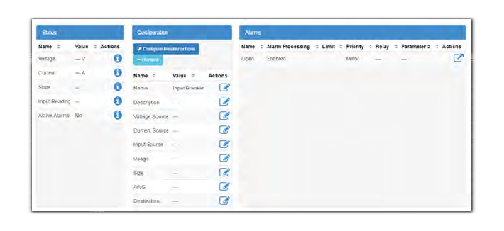
Cordex HP Controller Software Manual | 7 - Inverter Systems (Single T2S)
2. Click the more details icon of the breaker or fuse to configure.
3. In the Configuration table, enter the Name, Description and Input Source values. When the
value of the input source is Active, the breaker/fuse is open. Alternatively, click the Configure
Breaker or Fuse wizard to be prompted for the essential configuration required for the breaker/
fuse to function.
4. In the Alarms table, click the more details icon of the Breaker/Fuse Open alarm and configure as
required.
Page 114 0350058-J0 Rev AD

8. Line Power Systems
This section provides an overview of line power converters, how they function, as well as how to configure
a line power system.
8.1. Introduction to Line Power Systems
The power conversion modules (LP modules) in a line power system take a -48V nominal DC input
voltage and converts it to a different output voltage. There are three types of LP modules:
• LPS36 ±190V
• LPS36 ±137V
• eLimiter+ 57V
All three types have four independent output channels, each with a maximum output power of 100W. In
a line power system (LPS) the output of the channels from different modules can be combined to supply
power to loads at remote locations. Combining channels allows for supplying power to loads that may
exceed the 100W limit of a single channel.
The two LPS36 modules are designed for outdoor power applications that deliver power through existing
copper telephone wires. The eLimiter+ is designed for indoor power applications that use larger gauge
wire for power delivery.
Warning: Working with LP modules, especially LPS36, pose potentially fatal safety concerns. Refer
to the appropriate hardware manual before attempting to wire an LP system or to get more detailed
information about the electrical performance of these modules.
8.1.1. Components of a Line Power System
Systems with LPS36 modules are different than systems with eLimiter+ modules.
LPS36 modules require down converters at the remote end to convert the high voltage output to a
nominal -48V which is suitable for most loads.
The output of the eLimiter+ modules is already at -48V, so these systems do not require down converters.
Refer to the diagrams below for the typical components of an LPS.
0350058-J0 Rev AD Page 115

Cordex HP Controller Software Manual | 8 - Line Power Systems
Figure 63. Example LPS36 System
CXC HP
DC Source
Line Power
Module
LP Loads
CAN Bus
48V
± 190V
Figure 64. Example eLImiter+ System
CXC HP
DC Source
eLimiter+
Module
LP Loads
CAN Bus
48V
57V
Note: Due to the remote location of down converter modules, they are not monitored by the CXC HP
controller.
Page 116 0350058-J0 Rev AD

Cordex HP Controller Software Manual | 8 - Line Power Systems
8.1.2. Quick Reference for Configuring a Line Power System
Figure 65. Quick Reference for Configuring a Line Power System
Controller >
Inventory
Create Line Power System
System Type = 57V or +/-190V
System > Line Power System
>
Configure System
Module Assignment Rule = Automatic
Primary Output Display = Watts or Amps
Average Input Voltage
Total Output Current
Total Output Power
Total Input Current (Est.)
Total Input Power (Est.)
System > Line Power System
>
Status
Name
Description
Bay, Shelf, Slot IDs
Module Details & Alerts
Channel 1, 2, 3 & 4
System > Line Power System
> Inventory >
Line Power Modules
Name
Description
Shelf, Slot, Channel IDs
[Line Power Load]
System > Line Power System
> Inventory >
Line Power Channels
Name
Description
Status
Alarms
Power On / Power Off
System > Line Power System
> Inventory >
Line Power Loads
8.2. Creating a Line Power System
There is no line power system on a brand new CXC HP controller. You can create a new system from
scratch or import one from a configuration file that contains a system from another controller. It is possible
to create more than one line power system.
A new power system can be created from the controller LCD or the web, via the Controller > Inventory
menu. A wizard steps you through the process to create the new system. You can create three types of
systems: LPS36 ±190, LPS36 ±137, or an eLimiter+.
0350058-J0 Rev AD Page 117

Cordex HP Controller Software Manual | 8 - Line Power Systems
Figure 66. Create Line System Wizard
The new system will have a reasonable set of defaults and associated alarms where possible. Optional
configurable values, such as Name, Description, System Number, can be used to describe and organize
your system.
The Module Assignment Rule setting controls how newly discovered LP modules are treated. The two
options are Manual and Automatic. Manual groups all new LP modules into Unassigned Modules,
and then you can add them to the system manually. Automatic adds new, compatible LP modules to the
system automatically. This is the default setting.
You can configure the alarms associated with the LP system. You can enable or disable the alarms,
change the priority, map relays to the alarms, and where applicable, modify the thresholds.
To create a line power system:
1. Go to Controller > Inventory.
2. Click Create Line System. Name the system if required.
3. From the Select System Type drop-down, select the value that corresponds to your LP module
type. If there are LP modules already connected to the controller, they are preselected with the
correct option.
4. Follow the rest of the wizard instructions.
8.2.1. Creating a System from a Configuration File
A system can be created by importing from a configuration file. See the “Importing a System” section to
do this.
8.3. Configure the Line Power Modules
There are two settings that are applied to all LP modules: Input Voltage Low Shutdown and Input
Voltage Low Restart.
Page 118 0350058-J0 Rev AD

Cordex HP Controller Software Manual | 8 - Line Power Systems
When the input voltage falls below the low shutdown threshold, the LP modules will power off all output
channels. Set this threshold to a value that prevents over-discharge of the battery.
When the input voltage rises above the restart threshold, the units turn back on. The restart threshold
must be at least two volts above the shutdown threshold or the LP Module Configuration Error alarm
will activate (LPS36 only).
These settings are stored on the LP module itself which means that even if disconnected from the
controller the LP modules will still perform in this way.
To configure the LP modules:
1. Go to System > Line Power System > Configure System.
2. From the Configuration table, set the Input Voltage Low Shutdown threshold to the desired
value.
3. In the same table, set the Input Voltage Low Restart threshold to the desired value.
8.3.1. Shared Alarm Configuration
The Shared Alarm Configuration feature is a setting which can be used to enable/disable or change
the priority of alarms on all LP modules in a system. When using this feature you can configure both
the Channel Shutdown and the Module Failure alarms on the specific LP system being configured.
Configuring Channel Shutdown will apply the setting to each of the four channel shutdown alarms on
each LP module.
8.4. Line Power Module Alarms
LP modules assigned to a system, report active alarms which are displayed on the details page of each
specific module, and on the Active Alarms page. LP module alarms function the same as regular alarms
with the exceptions of shared configuration, as detailed in the previous section.
Each LP module has four channel alarms and a Module Failure alarm.
A Module Failure indicates a module-level failure such as, input voltage, high/low, high temperature or if
the module has lost communication.
0350058-J0 Rev AD Page 119

Cordex HP Controller Software Manual | 8 - Line Power Systems
A Channel Shutdown is activated if any channel shutdown alert such as, over voltage, ground fault, etc.
are active.
Both channel and module alarms provide an SNMP notification that identifies the alert/condition which
produced the alarm, and the physical location of the module (bay-shelf-slot-channel).
8.5. Configure the Line Power System Channels
Each LP module has four channels that can be given a name, description and assigned to a load. All
channels are listed in table that can be sorted and searched. You can also export all channel details to a
file.
To configure the channels:
1. Go to System > Line Power System > Inventory > Line Power Channels. You will see a table of
channels in the system. There is also a Export Channel Details button to export the information to
a .csv file.
Channels cannot be added or removed. It is also possible to configure channels and get detailed
channel information from System > Line Power System > Inventory > Line Power Modules and
clicking the more details icon for the module.
2. Click the more details icon for the channel you want to configure.
3. In the channel table, assign an optional name and description. This might be a channel address,
wire color or customer name.
4. In the channel table, assign an optional Line Power Load. To assign a load it is necessary to first
create a load. Refer to Configure the Line Power Loads to do this.
8.6. Configure the Line Power System Loads
A line power load represents the remote load that is powered by the LP module channels. Create a load
when you want to monitor and alarm separate remote loads. Creating a load allows all channels that have
been assigned to the load to be powered on or off as a group. To turn all the channels assigned to a load
on or off, use the Power On or Power Off buttons on the Configuration table.
You may add or remove loads as needed. Removing a load does not affect the power delivered.
Note: To assign channels to a load, refer to the section on Line Power System Layout or Configure
Line Power System Channels.
To configure the loads:
1. Go to System > Line Power System > Inventory > Line Power Loads. You will see a table for
loads in the system. This table shows how many channels are assigned to the load and the loads
total output current and power. Add or remove loads from this screen.
2. Click the more details icon for the load you want to configure.
3. In the Configuration table, assign the load a name and a description. Alpha recommends that you
assign the load a name that represents the actual load.
Page 120 0350058-J0 Rev AD

Cordex HP Controller Software Manual | 8 - Line Power Systems
4. Configure the load alarms as needed.
8.7. Line Power System Layout
The line power system Layout screen shows a graphical view based on the shelf and slot ID as reported
by the line power modules. This view allows a convenient way to view module status and to configure and
interact with individual channels.
8.7.1. Using the Layout Screen to View Module Status
The line power Layout screen provides a convenient way to view:
• Module shelf and slot position
• Output voltage, power and current for each module
• Module and channel alert status
• Module and channel information (detailed)
• Load information (detailed)
The following steps describe how to use the Layout screen to view module and channel status:
1. Go to System > Line Power System > Layout. This screen shows a grid of LP modules
organized by shelf ID vertically, and slot ID horizontally. Each module is represented by a rectangle
showing the output voltage and the output power for each channel. The information in the
rectangle is green to indicate that a module is operating normally.
It is possible to display channel output power or channel output current on this screen. Change the
Primary Output Display to the desired value in the System Properties table at System > Line
Power System > Configure System.
0350058-J0 Rev AD Page 121

Cordex HP Controller Software Manual | 8 - Line Power Systems
2. Select a channel for detailed information. If a module has an active alert then the green turns to
red to indicate an alert with the module or with a channel. If the alert is on a specific channel then
the specific channel will be highlighted red. If it is module alert only, then the channels will all show
green but there will be red border around the module. To get more detail on the active alert, select
the channel that has the alert (if it is a module alert select any channel that belongs to the module.
This shows a new table with channel details.
3. In the Channel Details table, click the more details icon for the Line Power Module to view active
alert information.
4. In the Module Alerts table sort by Value to bring the active alerts to the top of the table.
8.7.2. Using the Layout Screen to View Load Status
The following steps describe how to use the Layout screen to view load status.
1. Go to System > Line Power System > Layout.
2. Using the Line Power Load drop-down list, select a load. A table displays detailed information
about the load. You can modify the name, description, and other information about the load as well
as do all load management tasks from this page.
Page 122 0350058-J0 Rev AD

Cordex HP Controller Software Manual | 8 - Line Power Systems
8.7.3. Using the Layout Screen to Assign Channels to Loads
The line power Layout screen provides a convenient way to:
• View which channels have been assigned to the LP Loads
• Assign channels to an LP Load
• Unassign channels from Loads
• Add, remove, and rename Loads
To use the Layout screen to view and configure channels assigned to LP Loads:
1. Go to System > Line Power System > Layout. At the top of the table use the drop-down menu to
select an LP load. When None is selected, the channels that are not assigned to a load display as
highlighted.
2. Select a load from the drop-down menu. The channels assigned to this load will be highlighted.
0350058-J0 Rev AD Page 123

Cordex HP Controller Software Manual | 8 - Line Power Systems
3. To add a new channel to the load, select it. The channel rectangle will turn blue to indicate it is
selected.
4. In the layout table, click Assign Selected Channel(s) to Selected Load. In the channel details
table, the Line Power Load field will be populated with the name of the load.
By default, the Assign Selected Channel(s) to Selected Load and Unassign Selected
Channel(s) from Load buttons are disabled unless a load and channel(s) are selected.
5. To unassign a channel from the load, click a highlighted channel, and then click Unassign
Selected Channel(s) from Load. In the channel details table, the Line Power Load field will be
set to “- - -”
Page 124 0350058-J0 Rev AD

Cordex HP Controller Software Manual | 8 - Line Power Systems
6. To assign or unassign multiple channels at once, hold CTRL on the keyboard and click the
required channels which display as blue when selected.
7. Once all required channels are selected, use the Assign Selected Channel(s) to Selected Load
or Unassign Selected Channel(s) from Load buttons to assign and unassign multiple channels.
0350058-J0 Rev AD Page 125
9. Auxiliary Systems
This section provides an overview of the auxiliary system and how it is configured.
9.1. Introduction to Auxiliary Systems
The auxiliary system serves as a standalone system for monitoring the readings on a current or other
transducer. Both AC or DC current transducers can be used.
The typical application for this type of system is to monitor current flowing through the AC feeds into a site
or a power system.
When current transducers have been added to the system they display in the controller dashboard of the
LCD, and the Auxiliary System dashboard of the web interface. The auxiliary system does not presently
have any key status information for display on the LCD dashboard or in the system’s summary region on
the top of the main dashboard page on the web.
9.2. Create an Auxiliary System
To create an auxiliary system:
1. Go to Controller > Inventory and click the Create Auxiliary System button.
2. Go to System > Auxiliary System > Configure System and enter a Name and Description for
the system.
9.2.1. Creating a System from a Configuration File
A system can be created by importing from a configuration file. See the “Importing a System” section to
do this.
9.3. Current Transducers
The physical current transducer can be of the voltage-output type (0-5V or 0-10V)or current-output type
(4-20mA) type depending on the accuracy requirements. A 4-20mA type is more accurate because losses
in the sensor leads are inherently compensated.
A transducer with a voltage output can be connected directly to an L-ADIO voltage input. A transducer
with 4-20mA output must have a 500R resistor added across the voltage input. For AC, the current
transducer must be of the type which conditions the signal to provide a DC output proportional to the RMS
(or average) value. AC waveforms cannot be monitored by the LADIO input circuitry due to noise filtering.
9.4. Configure the Current Transducer
The system, by default does not contain any current transducers. You can add or remove current
transducers as needed. To configure a current transducer you need a voltage input on an ADIO. To
configure a current transducer with an IPM, you need a shunt input on an ADIO.
Page 126 0350058-J0 Rev AD
Cordex HP Controller Software Manual | 9 - Auxiliary Systems
To configure a current transducer:
1. Go to the system where you want to add the transducer and navigate to the inventory page. Go to,
System > Inventory > Other Transducers > Current Transducer. There will be a list of current
transducers in the system. Add or remove them from this page.
You may be using a current transducer with Interface & Power Module (IPM). This device takes
the voltage reading from a current transducer and divides the reading by 50. The factored voltage
reading is then sent to the L-ADIO Shunt Input.
2. Click the more details icon for the Current Transducer you wish to configure.
3. In the Configuration table, click on Configure Current Transducer to enter the configuration
wizard and complete the details.
4. Enter the Measurement Range in amps.
5. Enter the Range in Volts.
6. Select the CT Current Source. This can be any voltage source.
7. Optional: enter the Offset calibration for the Current Transducer if the reading error is too low or
too high.
9.5. Configure the General Purpose Transducer
The system, by default does not contain any general purpose transducers. You can add or remove
general purpose transducers as needed. To configure a general purpose transducer you need a voltage
input on an ADIO.
To configure a general purpose transducer:
1. Go to the system where you want to add the transducer and navigate to the inventory page. Go to,
System > Inventory > Other Transducers > General Purpose Transducer. There will be a list of
general purpose transducers in the system. Add or remove them from this page.
2. Click the more details icon for the General Purpose Transducer you want to configure.
3. In the Configuration table assign a name and a description.
4. Select the Transducer Input Source. This can be any voltage source or a custom data.
5. Enter the Transducer Input Minimum in Volts and Transducer Input Maximum in Volts.
6. Enter the Transducer Output Minimum and Transducer Output Maximum.
7. Select the Units and Precision
8. Optional: enter the Offset calibration for the calculated Value if the reading error is too low or too
high.
The Calculated Slope and the Offset are used to convert the Input Source Value to the Value. The
value is displayed in the selected units and precision.
0350058-J0 Rev AD Page 127
10. Distribution Systems
This section provides an overview of the operation and configuration of a distribution system and its
subsystems, panels and breakers.
10.1. Introduction to Distribution Systems
A distribution system is a way to define and track how the output power of a DC system is distributed. The
system may be composed of specialized ADIOs built for the purpose of distribution or via general-purpose
ADIOs in any configuration. The distribution system itself is really just a “container” to hold distribution
subsystems.
In the case of the specialized ADIOs (a smart subsystem), the subsystem will map one-to-one with the
ADIO. For example, a Smart BDFB ADIO module will be represented in the distribution system as one
subsystem. Manually created subsystems can be mapped to a number of ADIOs, and contain a user-
defined number of breaker/fuse panels and breakers themselves.
Within a subsystem there are a number of panels. A panel is a grouping of breakers/fuses.
A panel is considered a ‘downstream load’ of a subsystem and a breaker/fuse is considered a
‘downstream load’ of a panel. A breaker can then feed a referenced load. For example, a breaker
may feed a DC system or another subsystem. In this way, a user can create primary and secondary
distribution layouts. Understanding this relationship helps to visualize how a distribution system, its
subsystems, panels, breakers/fuses and referenced loads are organized.
A manually defined subsystem may contain up to 160 breakers across all panels. This could consist of
160 panels with one breaker each, 10 panels with 16 breakers each, or another combination. The smart
subsystems will contain the number of panels and breakers supported by the ADIO type to which they
correspond.
Page 128 0350058-J0 Rev AD

Cordex HP Controller Software Manual | 10 - Distribution Systems
Figure 67. Example of a DC System Distribution System
DC System
Distribution System
Battery
BDFBCXPS-C
Reference Load
Subsystem 1 Subsystem 2
10.2. Creating a Distribution System
There is no distribution systems on a brand new CXC HP controller. Creating distribution systems is done
via the Create Distribution System button located under the Controller > Inventory menu. There is no
configuration required at the system level.
You can also import a distribution system via a configuration file.
The CXC HP supports multiple distribution systems. Alpha recommends the use of multiple distribution
systems to separate the distribution of different voltage levels. For example, a user can create a 48V
Distribution System, and a 24V Distribution System. The multiple systems could also be used in different
ways, such as to separate primary and secondary distribution, or even physical layouts such as “first floor
distribution” and “second floor distribution”.
When first created, a distribution system is empty. Subsystems must be added to give the system
meaning. The system-wide voltage and current readings are Unknown when the subsystem is first
created. These values are mapped to sources via the System > Distribution System > Configure
System page. By default, the Voltage Source is set to Average All External Input Voltages and the
Current Source is set to Sum All External Input Currents.
External inputs, as mentioned above, mean inputs external to the Distribution System. Only subsystems
that are mapped as a referenced load in another system will be used to create system summary values
by default. This provides the opportunity to nest layers of subsystems within the same distribution system,
and have the system summary values computed properly. If a different behavior is required, the voltage
and current sources can be edited to sum or average all subsystems, or to point to any other voltage and
current sources available on the controller, including Custom Data.
To create a distribution system:
1. Go to Controller > Inventory and click the Create Distribution System button.
0350058-J0 Rev AD Page 129
Cordex HP Controller Software Manual | 10 - Distribution Systems
2. A system is immediately added to the Inventory table.
3. Go to System > Distribution System > Configure System and enter a Name, Description and
any other identifying information required.
10.2.1. Creating a System from a Configuration File
A system can be created by importing from a configuration file. See the “Importing a System” section to
do this.
10.3. Distribution Subsystems
Once a distribution system exists, at least one subsystem must be added. This is done via the System
> Distribution System > Subsystems menu on the web or LCD. There are two types of subsystems:
Smart Distribution Subsystem or User Defined Subsystem. Each type uses a wizard to assist in
creating and configuring a subsystem.
Generally a subsystem will correspond to a physical rack on the site. Subsystems that distribute power
from the same source should all be contained within the same distribution system. Multiple distribution
systems are possible, but should only be used if the representation of multiple distributions systems is
required.
For example, distribution equipment such as on different two different floors, may be better represented
by two distributions system rather than one.
The following sections describe the different subsystems and information on creating them.
10.4. Create a Smart Subsystem
A smart subsystem correlates one-to-one with a “smart” distribution ADIO, such as the Smart BDFB or
the Smart E2. The number of panels and breakers supported by that ADIO are created automatically.
During the wizard set up, you can map the ADIO for the subsystem. This can also be done later if the
ADIO is not available when the system is created. The smart subsystem will not function properly until the
correct type of ADIO is assigned.
In the first step of the wizard, there is an option to name the subsystem. The current smart subsystems
are the Smart BDFB or the Smart E2. From the list of ADIOs currently acquired by the controller, you can
choose the ADIO for this subsystem, or it can be done later via the System > Distribution System >
Subsystem > ADIO page. Once an ADIO is selected, you can choose to “locate” the ADIO to ensure
it is correct. It is also possible to give a custom name to the ADIO so that it is easily recognized in the
Modules > All Modules list.
In a smart subsystem, inventory is automatically created based on the system type. For example, a Smart
BDFB supports eight panels with 20 breakers per panel, and a Smart E2 has two panels with 11 breakers.
The ADIO inputs to panels and breakers are also mapped automatically.
A smart subsystem gets all available information from its associated ADIO. For each panel, the current
and voltage are measured by the ADIO, as well as any active alarms. On the Smart BDFB, one breaker
trip signal is available per panel. This means that the subsystem knows, at the panel level, that one or
more of the 20 breakers associated with that panel are tripped, but not which particular breakers. On the
Page 130 0350058-J0 Rev AD

Cordex HP Controller Software Manual | 10 - Distribution Systems
Smart E2, the individual breaker trip signals are provided by the ADIO, so they can be displayed at the
breaker level.
The Smart BDFB also has the ability to have its panels set up as “linked” to other panels, or “blank” if
unused. This information can be viewed from the System > Distribution System > Subsystem > Panel
page.
The Smart E2 has a temperature alert, which other ADIO types do not. There is a field called Over
Temperature Alert in the subsystem, which is only populated for E2-based subsystems.
Figure 68. Example of BDFB Distribution Subsystem
Distribution subsystem (BDFB)
Up to 20 Breakers per panel
Up to 8 breaker panels per BDFB
To create a smart distribution subsystem:
1. Go to System > Distribution System > Subsystems, and then click Create Smart Distribution
Subsystem. Follow the wizard.
You can now view the Smart Distribution Subsystem from the Distribution Subsystems table. No
further configuration is necessary. If you plan to reconfigure the smart ADIO, continue below.
2. Go to the System > Distribution System > Subsystem > ADIO menu.
0350058-J0 Rev AD Page 131

Cordex HP Controller Software Manual | 10 - Distribution Systems
3. Click the details icon of the assigned ADIO to view all its details including configuration and I/O.
(Ensure there is an ADIO assigned to the system first.)
4. In the Configuration File table use the Upload Configuration file to Controller and Get
Configuration File from ADIO buttons to send the configuration to the ADIO.
10.5. Create a User Defined Subsystem
Any type of distribution that is not a smart subsystem is called a user defined subsystem. The user can
specify the number of panels, breakers/fuses and shunts, and then quickly bulk-map the ADIO inputs to
shunt sources.
The first step of the wizard there is an option to name the subsystem. Next, specify the number of
breaker/fuse panels to create. There is a limit of 160 breakers across all the panels. This could consist of
160 panels with one breaker each, 10 panels with 16 breakers each, or some other combination. There is
an option to name each panel, specify the number of breakers/fuses, and specify the shunt configuration.
When finished you can still add/remove panels, breakers and shunts via their respective pages in the
subsystem tree. After panels, breakers and shunts have been added, specify the ranges of all the shunts
in the subsystem. These can be changed later via the Shunts table.
Figure 69. Example of a User Defined Subsystem
Distribution subsystem (CXPS-C)
Breaker / fuse
Shunt
Up to 24 shunt + fuse positions per bay
Each CXPS-C Bay is
one fuse panel
To create a user defined subsystem:
1. Go to System > Distribution System > Subsystems, click Create User Defined Subsystem,
and then follow the wizard.
2. In the Distribution Subsystems table, click the more details button to view the subsystem.
3. If you need to map the shunt sources, go to System > Distribution System > Subsystems >
Subsystem > Shunts, click Assign Dedicated ADIOs as Shunt Inputs, and then follow the
wizard.
Page 132 0350058-J0 Rev AD
Cordex HP Controller Software Manual | 10 - Distribution Systems
10.6. Configure the Panel Details
A panel is a grouping of breakers and/or fuses within a subsystem. A panel is considered a downstream
load of a subsystem. On smart subsystems, these are automatically created according to the number
of panels that the ADIO supports. For BDFB subsystems, the full eight panels are created, even though
some may be linked or blank. For E2 subsystems, two panels are created. On a user defined subsystem,
you can add up to 10 panels per subsystem.
To monitor a breaker or fuse trip associated with a panel, the Breaker/Fuse Source should be mapped
to a digital input as well. Again, for smart subsystems, these values are automatically set based on the
assigned ADIO.
There are several text fields associated with a panel, which the user may find useful to further describe
the panel, such as Description, Fuse Number, Fuse Size, and Fuse Maximum Amperage. These are
optional and may be filled in by the user if desired.
There are three alarms provided on each panel: Breaker Trip, Loss of Feed, and Over Current. On a
user defined subsystem, thresholds for these alarms are set as applicable. The Breaker Trip alarm is
not a threshold alarm; it is calculated based on the Breaker/Fuse Source set for the panel. On a smart
subsystem, alarms come directly from the ADIO and thresholds must be set on the ADIO.
A concept specific to the BDFB is linking panels. Panels may be linked up to the panel above, or linked
down to the panel below, based on the loads. They may also be set blank if unused. When one or more
panels are linked, one must still be designated as the “shunt”, and the others are configured as linked.
The voltage and current measurements are taken from the shunt panel only. The breaker trips are still
monitored on all linked panels. The configuration of panels as shunt, linked up, linked down, or blank
must be done via the BDFB ADIO. The CXC HP controller only reports the details.
To configure panel details:
1. Go to System > Distribution System > Subsystems, and click the details icon for the subsystem
that contains the panels to configure.
2. Enter the Subsystem Details menu.
3. In the Downstream Loads table, click the details icon for the panel to configure.
Note that in smart subsystems, the configuration is done automatically via ADIO.
4. In the Configuration table, edit the details of the panel.
10.7. Configure the Breaker/Fuse Details
In a distribution system, a breaker/fuse represents a downstream load of a panel. Breaker/fuse
configuration can be accessed directly under the subsystem, or from the panel in which it resides.
Within the Breaker/Fuse configuration, there are a number of text fields that can be used to better
describe and define the breakers. These cannot be obtained from the ADIO in any automatic way.
They need to be configured manually. These fields include a Description, Usage, Size, AWG, and
Destination field for each breaker. Manually editing all of these fields is a lot of work for large systems.
The most effective way to do this is to download and edit the fields in spreadsheet format. This makes it
easy to cut and paste, use macros, or reuse entered text for other purposes (such as printing labels).
0350058-J0 Rev AD Page 133

Cordex HP Controller Software Manual | 10 - Distribution Systems
Note: The input source of the breaker is set automatically because the value is constrained by
physical wiring on the panel. Although the field is editable, it will be set back to the correct value if it is
manually changed. This is true for E2 subsystems only.
To configure all breakers/fuses in a distribution subsystem:
1. Go to System > Distribution System > Subsystems and click the details icon for the subsystem
that contains the breakers/fuses to configure.
2. Enter the Breakers and Fuses menu.
3. Click Export to CSV to download a file to the computer. Open this file in a spreadsheet program.
Alternatively, you can export a CSV file to configure just the breakers/fuses associated with a
single panel. Go to Subsystem > Subsystem Details > Downstream Loads, and then click the
details icon of the Panel that contains the breakers/fuses configuration you want to change. In the
Downstream Loads table, click Export to CSV.
4. In the spreadsheet program, enter the breaker/fuse information as needed. Ensure that you do not
to change the Owner or Identity column. This is required to import the configuration correctly. Save
the file.
5. Press the Import Configuration from CSV button and select the edited file.
6. Once uploaded, verify the configuration is correct.
10.8. The Subsystem Layout
Distribution subsystems contain a Layout page to visualize the layout of the panels. This page shows the
panels, including a graphical representation of whether the panels are linked (in Smart BDFB).
• In smart subsystems, panels are arranged two panels per row, to best match the LCD screens of
the smart devices.
• In user defined subsystems, panels are arranged one per row to more closely represent a physical
distribution system.
Clicking a panel will display the details on the right side of the layout page, as well as a table for breakers,
and for shunts (user defined subsystem only). This is available via the web only.
To view the Layout page, go to System > Distribution System > Subsystems, then click the details
icon of the subsystem required. Click to enter the Layout menu.
Page 134 0350058-J0 Rev AD

Cordex HP Controller Software Manual | 10 - Distribution Systems
Figure 70. Distribution Subsystem Layout
10.9. Map Shunts to ADIO Inputs
The Map Shunts to ADIO Inputs wizard assists the process of mapping ADIO shunt inputs to shunt
inventory items. Alpha recommends that your ADIOs are named before launching this wizard to help
identify which ADIOs to select.
Using the wizard you can select to map in bulk or individually. In bulk mode, the current sources of the
shunt inventory in the subsystem are set automatically to the shunt inputs of the ADIOs selected in the
wizard; the ADIOs will be mapped in the order in which they were selected in the wizard. In individual
mode, you can select an ADIO shunt input for each Shunt.
Within the distribution system, this wizard is only available for user defined subsystems. You can launch
this wizard from any of the tables in subsystems that show shunts. The following example shows how to
configure a subsystem for a CXPS-C.
To create a CXPS-C distribution subsystem:
1. Follow the steps detailed in the Creating a User Defined Subsystem section, creating six panels,
with four breakers per panel, and one shunt per breaker.
2. Ensure that four 6I ADIOs are acquired and named as per the schematic (#1-#4).
3. Go to System > Distribution System > Subsystems > Subsystem > Shunts, and click Map
Shunts to ADIO Inputs.
4. On the Shunt Mapping Type step, ensure the mapping type is selected as Map Shunts in Bulk
and click Next.
5. Leave the first panel selected in the Select Starting Panel step, and click Next.
6. On the ADIO To Shunt Configuration step, set the ADIO Configuration as ADIOs Wired
Sequentially and click Next.
0350058-J0 Rev AD Page 135
Cordex HP Controller Software Manual | 10 - Distribution Systems
7. Select ADIO #1 from the drop-down, and then click Add Selected ADIO to List. You will see the
list below update with the ADIO you just selected.
8. Repeat for ADIOs #2 - #4, and then click Next.
9. The Review step details which inputs are mapped to which shunts. Review to ensure it matches
the wiring schematic.
10. Click Next, and the 24 inputs of the four 6I ADIOs will now be mapped to the 24 shunts in the user
defined subsystem.
Page 136 0350058-J0 Rev AD
11. DC Source Systems
This section provides a brief overview of the components and functions of a DC Source System. In this
system, DC Sources external to the controller (PV cells or DC generators), can be created and monitored.
11.1. Creating a DC Source System
There is no DC Source system on a brand new CXC HP controller. Creating a DC Source system is done
via using Create System wizard. There is no configuration required at the system level.
You can also import a DC Source system via a configuration file.
The CXC HP supports multiple DC Source systems. It is recommended to use multiple DC Source
systems to separate different types of DC Sources contributing to the DC bus. For example, a user can
create a PV DC Source System, and a Generator DC Source System. This is optional, and a users can
group DC Sources together however makes the most sense for their specific use case.
When first created, a DC Source system is empty. DC Sources must be added to give the system
meaning. The system-wide voltage and current readings are Unknown when the system is first created.
These values will be the average of all DC Source voltages, and the sum of all DC Source currents.
To create a DC Source system:
1. Go to Controller > Inventory and click the Create System button to launch the Create System
wizard.
2. From the drop-down menu, select DC Source System, then click Done.
3. A DC system is added to the Inventory table.
4. Go to System > DC Source System > Status & Config and enter a Name, Description and any
other identifying information required.
The Linked System indicates which system will have the DC source in its power flow.
11.2. Create and Configure a DC Source
A DC Source will represent one single piece of inventory which is external to the controller, providing DC
power to the bus. For example, a DC Source could be a PV array.
A special type of DC Source is provided to model a DC Generator. This DC Source has additional
capabilities for controlling a generator using a relay to start and stop it, based on a voltage or a set of
optional conditions.
To create and configure a DC Source:
1. Go to System > DC Source System > DC Sources.
2. In the DC Sources table, select one of two types of DC sources.
• A generic DC Source.
• A DC Generator is a specialized type of DC Source that can be controlled through use of a
relay.
0350058-J0 Rev AD Page 137

Cordex HP Controller Software Manual | 11 - DC Source Systems
3. After the DC Source has been added, click on the more details icon.
4. In the Configuration table, set the Name and Description to identify the DC Source.
5. In the Configuration table, set the Voltage Source to the ADIO voltage sensor reading that is
monitoring the voltage of this DC Source. Do the same for Breaker/Fuse Source (if applicable).
6. In the Configuration table, set the Current Source to the configured Shunt that is monitoring the
current of this DC Source.
Note: A Shunt needs to be created and configured before the Current Source of this DC
Source can be configured.
11.3. DC Generator
A DC Generator is a specialized type of DC Source which allows a generator to be started and stopped
with a relay.
The standard condition on which to start or stop a generator is based on a voltage. The controller allows
the user to choose any voltage in the system and set it as the Voltage to Monitor, with a start threshold
and a stop threshold. The generator will be started if the Voltage to Monitor falls below the Start Voltage
Threshold, and will be stopped if the Voltage to Monitor climbs above the Stop Voltage Threshold.
The optional start or stop conditions can be used to start and stop the generator based on other types of
conditions. For example, the battery State of Charge could be used. The ability to use Custom Data or
other system values gives the generator control a lot of flexibility; however, care must be taken to ensure
that the start and stop conditions make sense. Otherwise, it is possible for the user to create, for example,
a start condition that is always true, in which case the generator would not stop running.
The Minimum Runtime assures that the generator will not be started to only run for too short a period
of time. Once the generator has started, it will continue to run for the Minimum Runtime even if a stop
condition has become true.
The Maximum Runtime is intended to ensure that the generator does not continue to run indefinitely even
if no stop condition comes true. After running for the Maximum Runtime, the generator will attempt to shut
down. It should be noted that if a start condition is still true, it would start up again immediately. In that
case, an event message will be logged. Additionally, there is a Generator Running Too Long alarm that
may be enabled to help alert the user to this situation.
11.3.1. Create and Configure a DC Generator
To configure a DC Generator:
1. Go to System > DC Source System > DC Sources.
2. In the DC Sources table, click Add DC Generator.
3. After the DC Generator has been added, click on the more details icon.
4. In the Generator Control table, click the Configure Generator Control button to run the
configuration wizard.
5. In the Generator Control dropdown menu choose from the following:
• Enabled Chose enabled if the generator can be controlled by a relay.
Page 138 0350058-J0 Rev AD

Cordex HP Controller Software Manual | 11 - DC Source Systems
• Disabled If disabled is chosen no further configuration is required.
6. Under Generator Control Signals select the Generator Control Relay and the Generator
Status Signal Source. Click Next.
Note: The Generator Control Relay is mandatory as it is the relay that will be used to start
and stop the generator.
Note: The Generator Status Signal Source is optional, but it should be mapped to a digital
input which can be used to monitor whether or not the generator is running.
7. Under Voltage to Monitor, choose a voltage signal to be monitored.
a. Enter a Start Voltage Threshold.
b. Enter a Stop Voltage Threshold.
c. Click Next.
8. Review your settings and click Next.
Additionally, the alarms for Generator Control may be configured. The Generator Status Mismatch
alarm will be active if there is a Generator Status Signal Source configured, and the status does not
match what is expected. For example, if the Generator Command Status indicates that the generator
should be running, but the Generator Status Signal Source indicates that it is not (as reported in the
Generator Running status field), the Generator Status Mismatch alarm will become active. Similarly,
if the Generator Command Status indicates that the generator should not be running, but the signal
indicates that it is, the alarm will activate. The Generator Running Too Long alarm is disabled by
default. If enabled, it will indicate if the generator has run past the Maximum Runtime due to a start
condition that is still true.
11.4. DC Source System Effect on Other Systems
A DC Source System is useful in representing external equipment for inventory purposes. Its strength lies
in making DC System calculations more accurate. Many DC systems will use a battery shunt to read the
battery current, and the load current will be calculated using = (Total Output Current - Battery Current).
In situations where there are DC Sources external to the controller, this calculation would not be sufficient.
When DC Source Systems are created, two new calculations are available:
• = (Total Output Current - Battery Current + Total DC Source Current)
• = (Total Output Current - Total Load Current + Total DC Source Current)
These can be used when a DC Source is present to ensure the contributions of the DC Sources to the
system currents will be accurate. In the case that both load and battery use shunts to measure current, a
Custom Data can be used to include the contributions from the DC sources.
In addition to the above, DC Source Systems will appear on the Power Flow in the relevant diagrams,
giving a more complete picture of all the power sources flowing through the system.
Note:
0350058-J0 Rev AD Page 139
Cordex HP Controller Software Manual | 11 - DC Source Systems
At present, a DC Source only appears on the Power Flow for a DC System and its battery and on the
FXM system and its battery.
Page 140 0350058-J0 Rev AD
12. AC Source Systems
This section provides a brief overview of the components and functions of an AC Source System. AC
Source Systems are intended to be used by customers who need to model multiple AC Sources for their
system. An example might be a system that has a set of rectifiers fed from AC mains, and a different set
fed from a generator. For customers with a single AC Source, or even multiple sources such as mains
and generator which switch over automatically with a transfer switch, it is usually not necessary to model
an AC Source system.
12.1. Creating an AC Source System
There is no AC Source system on a brand new CXC HP controller. Creating an AC Source system is
done using the Create System wizard. There is no configuration required at the system level.
You can also import a AC Source system via a configuration file.
The CXC HP supports multiple AC Source systems. Multiple AC Sources can be modeled within the
same AC Source System. Users can group AC Sources together to best suit their specific use case.
When first created, an AC Source system is empty. AC Sources must be added to give the system
meaning. The system-wide voltage readings are Unknown when the system is first created. These
values will be the average of all AC Source voltages for each phase.
To create an AC Source system:
1. Go to Controller > Inventory and click the Create System button to launch the Create System
wizard.
2. From the drop-down, select AC Source System, then click Done.
3. An AC system is added to the Inventory table.
4. Go to System > AC Source System > Status & Config and enter a Name, Description and any
other identifying information required.
12.2. Create an AC Source
An AC Source will represent one AC input to the system, for example AC Mains.
To create and configure an AC Source:
1. Go to System > AC Source System > Inventory.
2. In the AC Sources table, click Add AC Source. The Add AC Source wizard will launch.
3. Set the Name to identify the AC Source.
4. Select one of two types of AC Sources.
• A Simple AC Source can be used to model an AC Source with voltage readings for each
phase. This source includes AC Fail and Urgent AC Fail alarms.
• A Generator is a specialized type of AC Source which allows the use of a relay to start and
stop a generator based on a set of conditions to be configured later.
0350058-J0 Rev AD Page 141

Cordex HP Controller Software Manual | 12 - AC Source Systems
5. Select the Phase for your AC Source.
6. On the Alarms page, select whether the AC Input Fail alarm should be enabled for this source.
Select Yes or No.
7. On the Voltage Readings page, select the system from which the AC Source will obtain its
readings.
8. If a DC System was chosen for the Voltage Readings source in step 7, there will be an option to
run the separate Map Rectifiers to AC Source wizard on the Results page.
Note: If the Voltage Reading Source System has been set to a DC System, the phase voltage
sources will be automatically set to the mapped rectifiers. If the Voltage Reading Source System has
been set to an Inverter system, these phase voltage sources will be set to read from the Inverter system.
If the Voltage Reading Source System is left unknown, these phase voltage sources should be set to read
from transducers or any other voltage sources as desired.
Note:
If the Voltage Reading Source System has been set to a DC System, and the AC Fail alarms are
enabled, the AC Input Fail alarm will be calculated in the same manner as the DC System’s AC Fail
alarm. If 90% of the rectifiers mapped to this AC Source have failed, then the AC Input is assumed to be
failed. Otherwise, if the Voltage Reading Source System is set to an Inverter system, or left unset, the
AC Input Fail alarm will be activated if any one of the phase voltages falls below 10V.
12.2.1. Map Rectifiers to an AC Source
An AC Source can get its data from either a DC System, an Inverter System, or from Transducers.
To map rectifiers from a DC System to an AC Source:
1. Run the Map Rectifiers to AC Source wizard. This can either be run directly from the results page
of the Add AC Source wizard, or launched from System > AC Source System > Inventory > AC
Source page.
2. Choose rectifiers to map from the Selected column. If rectifiers have previously been mapped to
this source, they will show as selected. Click Next.
3. The Review step will show the changes requested. Pressing Cancel at this time will discard your
changes. Click Next to accept your changes.
The chosen rectifiers will be mapped to this AC Source.
Note: The rectifier mapping can also be changed one-by-one for each rectifier, in the System > DC
System > Inventory > Rectifiers > Phase Mapping table.
Note:
The rectifiers can also be assigned to a particular phase. This can be done through the System > DC
System > Inventory > Rectifiers > Phase Mapping table.
Page 142 0350058-J0 Rev AD
Cordex HP Controller Software Manual | 12 - AC Source Systems
Rectifiers that are left at the default setting of No Phase will be assumed to belong to Phase 1. If a
rectifier has been set to a phase that does not exist, that rectifier’s voltage values will not be included in
the voltage calculations for the AC Source.
12.3. AC Generator
An AC Generator is a specialized type of AC Source which allows a generator to be started and stopped
with a relay.
The standard condition on which to start or stop a generator is based on a voltage. The controller allows
the user to choose any voltage in the system and set it as the Voltage to Monitor, with a start threshold
and a stop threshold. The generator will be started if the Voltage to Monitor falls below the Start Voltage
Threshold, and will be stopped if the Voltage to Monitor climbs above the Stop Voltage Threshold.
The optional start or stop conditions can be used to start and stop the generator based on other types of
conditions. For example, the battery State of Charge could be used. The ability to use Custom Data or
other system values gives the generator control a lot of flexibility; however, care must be taken to ensure
that the start and stop conditions make sense. Otherwise, it is possible for the user to create, for example,
a start condition that is always true, in which case the generator would not stop running.
The Minimum Runtime assures that the generator will not be started to only run for too short a period
of time. Once the generator has started, it will continue to run for the Minimum Runtime even if a stop
condition has become true.
The Maximum Runtime is intended to ensure that the generator does not continue to run indefinitely even
if no stop condition comes true. After running for the Maximum Runtime, the generator will attempt to shut
down. It should be noted that if a start condition is still true, it would start up again immediately. In that
case, an event message will be logged. Additionally, there is a Generator Running Too Long alarm that
may be enabled to help alert the user to this situation.
12.3.1. Create an AC Generator
To create an AC Generator:
1. Go to System > AC Source System > Inventory.
2. In the AC Sources table, click Add AC Source. The Add AC Source wizard will launch.
3. Set the Name to identify the AC Source Type.
4. Select Generator from the AC Source Type drop-down menu. Click Next.
5. Select the Phase for your AC Source. Click Next.
6. On the Alarms page, select wither the AC Input Fail alarm should be enabled for this source.
Select Yes or No.
7. On the Voltage Readings page, select the system from where the AC Source will obtain its
readings.
8. Review your settings and click Next.
9. In the Results step, there will be an option to run the Configure Generator Control wizard.
Alternatively, this wizard can be run from the Generator Control table within the details of the new
AC Generator source.
0350058-J0 Rev AD Page 143

Cordex HP Controller Software Manual | 12 - AC Source Systems
If the user wishes to use the optional start and stop conditions to start and stop the generator, these may
be configured in the Optional Start/Stop Conditions table.
Additionally, the alarms for Generator Control may be configured. The Generator Status Mismatch
alarm will be active if there is a Generator Status Signal Source configured, and the status does not
match what is expected. For example, if the Generator Command Status indicates that the generator
should be running, but the Generator Status Signal Source indicates that it is not (as reported in the
Generator Running status field), the Generator Status Mismatch alarm will become active. Similarly,
if the Generator Command Status indicates that the generator should not be running, but the signal
indicates that it is, the alarm will activate. The Generator Running Too Long alarm is disabled by
default. If enabled, it will indicate if the generator has run past the Maximum Runtime due to a start
condition that is still true.
12.3.2. Configure Generator Control
You can access the Configure Generator Control wizard from the Creating an AC Generator.
To configure the AC Generator:
1. Run the Configure Generator Control wizard. This can either be run directly from the results
page of the Add AC Source wizard, or launched from System > AC Source System > Inventory
> AC Source page.
2. In the Generator Control dropdown menu choose from the following:
• Enabled Chose enabled if the generator can be controlled by a relay.
• Disabled If disabled is chosen no further configuration is required.
3. Under Generator Control Signals select the Generator Control Relay and the Generator
Status Signal Source. Click Next.
Note: The Generator Control Relay is mandatory as it is the relay that will be used to start
and stop the generator.
Note: The Generator Status Signal Source is optional, but it should be mapped to a digital
input which can be used to monitor whether or not the generator is running.
4. Under Voltage to Monitor, choose a voltage signal to be monitored.
a. Enter a Start Voltage Threshold.
b. Enter a Stop Voltage Threshold.
c. Click Next.
5. Review your settings and click Next.
The generator has now been configured.
Page 144 0350058-J0 Rev AD
13. FXM-HP Systems
For the components and functions of a FXM-HP system, please see Alpha FXM-HP 650, 1100, 2000 UPS
Product Manual, Technical Guide: 0170022-J0.
0350058-J0 Rev AD Page 145
14. Controller Redundancy
For information on the Controller Redundancy function, please see the Controller Redundancy Integration
Guide.
Page 146 0350058-J0 Rev AD

15. Power Flow
This section provides an overview of the Power Flow feature.
15.1. Introduction to Power Flow
Power Flow is only available via the web interface of the controller. From the main dashboard, it displays
live information about the power system and its inventory items, as well the relationships and the flow of
power between them.
Power Flow is intended to be a single point for monitoring and troubleshooting the system. Key
information and alarms are shown and you can use Power Flow to quickly drill down and investigate any
alarms. A Power Flow for a DC System is shown below.
Figure 71. Power Flow for a DC System
15.2. Accessing the Power Flow
Power Flow can be accessed through the menu bar in the web interface. If a system that is supported by
Power Flow has been created, the Power Flow for that system will automatically appear in the drop down
as shown in the figure below.
0350058-J0 Rev AD Page 147

Cordex HP Controller Software Manual | 15 - Power Flow
Figure 72. Navigating to Power Flow
Note: In version 6.20 Power Flow supports DC, AMPS HP2, Distribution, and Line Power
Systems, and Battery Subsystems. If your site has one or more of these systems, go to Controller >
Inventory to create them.
15.2.1. Getting Help
Help for the Power Flow feature can be accessed from any Power Flow by clicking the Help icon.
15.2.2. Using Power Flow Configuration Suggestions
Power Flow can detect a missing configuration from the system’s inventory. In such instances, a special
node will appear to allow quick configuration of the system. Clicking on the node will bring up a dialog to
set the missing configuration.
Figure 73. Power Flow Configuration Suggestions
This feature can be disabled under Controller > Configure Controller > User Interface Preferences >
Power Flow Configuration Suggestions.
Page 148 0350058-J0 Rev AD

Cordex HP Controller Software Manual | 15 - Power Flow
15.2.3. Configuring the Default Power Flow
If your site has multiple systems supported by Power Flow, you can configure a default. The chosen
Power Flow will display whenever you click Power Flow in the menu bar.
To set or change the default Power Flow, go to Controller > Configure Controller > User Interface
Preferences and set the Default Power Flow field.
15.3. Interacting with the Power Flow
Power Flow is an interactive diagram, as such one can expand elements to view more information, or
click on element icons to navigate. The figure below highlights the interactive elements of the Power Flow
diagram.
Figure 74. Interacting with the Power Flow
The controls are located alongside the Help button in the top left corner of the Power Flow. The Expand
All button lets you immediately view all the details of the Power Flow by showing all fields and alarms.
The Collapse All button returns the diagram to the compact status summary state.
0350058-J0 Rev AD Page 149

Cordex HP Controller Software Manual | 15 - Power Flow
Figure 75. Power Flow Controls
15.4. Controller Power Flow
The controller Power Flow presents an overview on the systems configured on the site and the flow of
power between them. From here you can go to the Power Flow of individual systems by clicking on that
system’s icon.
Grayed out Inventory items are there to help draw a more complete picture, or can be placeholders for
future systems.
Figure 76. Controller Power Flow
Page 150 0350058-J0 Rev AD

Cordex HP Controller Software Manual | 15 - Power Flow
15.5. Power Flow for Systems Managed by Different Controllers
For systems that are managed by different controllers but are electrically connected, Data Sharing can
be used together with the Controller Power Flow to visually see the flow of power between the two
systems.
Note: In version 6.20, DC, AMPS HP2 Systems, and Battery System can be shared and shown on
the Controller Power Flow.
Figure 77. Using Data Sharing to Create Power Flow Across Different Controllers
Components drawn on Power Flow that are managed by a different controller will have a reference to the
Data Subscription they originate from. Clicking on these references will navigate to the user interface of
the managing controller.
0350058-J0 Rev AD Page 151
16. Maintaining the System
When maintaining your system always check for known issues within the readme file that ships with your
software. This section of the manual covers the following:
• Rectifier maintenance
• Inverter and T2S maintenance
• LPS maintenance
• Batteries and battery maintenance
• LVD maintenance
16.1. Rectifier Maintenance
This section covers the following: rectifier alarms, rediscovering CAN devices and inserting unassigned
modules.
16.1.1. Rectifier Alarms
Possible problems with rectifiers are indicated by either a Rectifier Minor or Rectifier Fail alarm. These
alarms are activated if one or more rectifiers have active alerts. Individual devices that are normally
controlled as a group, such as rectifiers, have alerts instead of alarms.
Go to the Troubleshooting section for more detailed information on rectifier alarms and alerts.
16.1.2. Insert Unassigned Modules
To assign rectifiers:
1. From the main menu go to System > DC System > Inventory > Rectifiers > Status.
2. In the Modules Available for Assignment table, click the Assign button next to the rectifier you
want to assign. You can also assign all the rectifiers by clicking Assign All. If this table is empty,
there are no compatible rectifiers detected.
3. The rectifier moves from the Modules Available for Assignment to the Status table and is
automatically configured to match what is contained in System > Inventory > Rectifiers >
Configuration menu.
16.2. Inverter and T2S Maintenance
This section covers inverter and T2S maintenance including: replacing, identifying, alarms and alerts, DC
priority and AC input power limit.
Changing the System Configuration
Once the system has been created, most of the system configuration cannot be changed. The number of
phases, number of DC groups and number of AC groups cannot be changed. If any of these values are
incorrect the inverter system must be re-commissioned and all inverters unplugged.
Page 152 0350058-J0 Rev AD

Cordex HP Controller Software Manual | 16 - Maintaining the System
Adding or Removing Inverters
If more inverters are needed to increase capacity, the Add Inverters wizard guides users through this
process.
Important:
To ensure the T2S is configured correctly, it is necessary to use these wizards to add or remove inverters
from the system. This ensures that the correct number of inverters, and the correct number of redundant
modules in each phase. This is important for the operation of T2S alerts and alarms.
Figure 78. Add/Remove Inverters
Go to System > Inverter System > Inventory > Inverters > Status to access the Add Inverters wizard.
If inverters must be removed from the system, use the Remove Inverters wizard. Go to System >
Inverter System > Inventory > Inverters > Status to access the Remove Inverters wizard.
16.2.1. Maintenance Bypass
For system configurations that use a generator for the AC input, the safest way to initiate a maintenance
bypass is to follow the instructions in the Initiate Zero Phase Shift wizard. This wizard should be used
whenever the inverter system has to be put into or taken out of bypass. This prevents the inverters from
turning off when the bypass switch briefly short-circuits the AC input and output.
Go to System > Inverter System > System Functions > Zero Phase Shift to access the Initiate Zero
Phase Shift wizard.
The wizard shifts the phase and voltage of the AC output to match the input.
16.2.2. Taking Power from DC Source
The inverter system can take power from the DC source (usually batteries) under three conditions:
0350058-J0 Rev AD Page 153
Cordex HP Controller Software Manual | 16 - Maintaining the System
1. AC mains is lost;
2. Manual DC Priority is enabled;
3. Input power limit is enabled.
When AC mains is lost, the inverters will always take power from the DC source if available.
16.2.2.1. Using Manual DC Priority
It is possible to manually instruct the inverters to take some amount of power from DC. This can be useful
for testing or to manually reduce the AC input power during peak periods. When both Manual DC Priority
and AC Input Power Limit are enabled, the feature with the higher resultant Desired DC Input Power
will take priority. To use Manual DC Priority:
1. Go to System > Inverter System > System Functions > Manual DC Priority.
2. From the Manual DC Priority table, click the edit icon.
3. Select Enable in Manual DC Mode drop-down menu and click save.
4. Click the edit icon to set the Desired DC Input Power to the desired value. This value is a
percentage of output power that will be taken from DC (with the rest coming from AC input).
5. Disable Manual DC Mode when complete.
16.2.2.2. Using AC Input Power Limit
The AC Input power limit is a feature that allows the controller to dynamically adjust the amount of power
taken by the AC input, by taking some power from the DC input. The controller will continue to take
power from the AC input until a user configured power limit threshold is reached. At this point, the inverter
system will begin to draw power from its DC bus. When both Manual DC Priority and AC Input Power
Limit are enabled, the feature with the higher resultant Desired DC Input Power will take priority.
1. Go to System > Inverter System > System Functions > AC Input Power Limit.
2. Enable the AC Input Power Limit.
3. Set the Desired AC Input Power to the required value. The controller will attempt to limit the AC
input power to this value by taking some power from the DC input.
4. Disable AC Input Power Limit when complete or when the battery needs to be charged.
The battery may be depleted and require charging.
16.2.3. Replace Fan
The fan inside each inverter has a limited lifetime. When this lifetime has expired the inverter will have an
active alert called Fan Life Elapsed. To prevent an unexpected fan failure that could compromise system
redundancy, it is recommended that the fan be replaced when this alert occurs.
To clear the alert, go to System > Inverter System > Inventory > Inverters > Status, and click the
details icon of the inverter with the alert, then press the Clear Fan Life Elapsed Alert button.
Page 154 0350058-J0 Rev AD

Cordex HP Controller Software Manual | 16 - Maintaining the System
16.2.4. Identifying an Inverter
If an inverter is in alert it is usually necessary to identify and locate the inverter in the rack. There are two
ways to do this:
1. Go to System > Inverter System > Inventory > Inverters > Status. This view shows all inverters
within the system in a table view. One column within the table displays the number of active alerts.
Find an inverter with an alert and click the Locate button. This will cause the LEDs on the front
panel of the inverter to flash for two seconds.
2. You can also click the details icon of the inverter. This view shows the bay, shelf and slot ID of
the inverter in the Inverter Mapping table. Normally this information is populated during system
commissioning, but it can also be changed here in case it is incorrect or was not initially set.
Note: If these values have been set, use them to physically locate the inverter. If the values
have not been set or appear to be incorrect, you can use the Locate button to find the inverter and
set the bay, shelf and slot ID as required.
16.2.5. Alarms and Alerts
The inverter system has a set of alarms that are generated by the alerts on the T2S and inverters. The
system alarms are shown in the Active Alarms table.
To see all the active alerts within the system, go to System > Inverter System > Live Alerts. This live
information comes from the T2S, and is the source of inverter system alarms.
When the inverter system has an active alarm, go to the Live Alerts table. The information in this table
indicates which T2S or inverter to investigate to find the cause of the alarm.
16.2.6. Replacing a T2S
If a T2S fails and needs to replaced, remove the old T2S and plug in the new T2S. Go to Modules >
All Modules and use the Replace T2S wizard to partially transfer configuration from the old T2S to the
new T2S. It may be necessary to wait for up to 20 minutes as the new T2S continues to be configured by
communicating with the inverters.
If system is not operating properly after waiting, then the system needs to be recommissioned for the T2S
to be configured correctly. For a single T2S inverter system, follow the instructions below. If the inverter
system has four T2Ss, refer to the chapter Inverter System (Four T2S).
1. Unplug the failed T2S.
2. Go to System > Inverter System > Inventory > T2Ss and click Forget All in Comms Lost. The
T2S will disappear from the table.
3. Insert the new T2S, and then wait for it to display in the Modules Available for Assignment table.
It will take several minutes for the controller to acquire the new T2S. In general it is assigned to
the system automatically, and displays in the T2Ss table. If it does not occur, use the Assign All
button to do this manually.
4. Put the system in Bypass to keep the load powered during the commissioning process.
0350058-J0 Rev AD Page 155
Cordex HP Controller Software Manual | 16 - Maintaining the System
5. Go to System > Inverter System > Configure System and click the Commission Inverter
System wizard in the Configuration table.
6. Follow the wizard instructions to recommission the system.
7. When completed, press the Add Inverters button to launch the add inverters wizard and add all
the inverters to the system. You can also launch this wizard from System > Inverter System >
Inventory > Inverters > Status.
The T2S has been replaced, and the inverter system has no active alarms.
16.2.7. Shelf Layout
Shelf layout is only available via the web.
When the inverters have been configured with bay, shelf and slot ID, the Shelf Layout page displays a
physical view of the inverters, the alert status and the output power of each inverter. The text that shows
the output power is a link that opens a new page to display the inverter details.
For inverter systems that use four T2S and TUS modules; TUS modules will display in the Shelf Layout
page, but because they do not have bay/shelf/slot information they are only displayed in the table.
16.3. Line Power System Maintenance
This section covers line power system maintenance including: replacing LP modules, and turning off
power to the loads.
16.3.1. Powering On and Off Line Power Loads
A line power load usually has multiple channels from different LP modules assigned to it. It may be
necessary to occasionally power off then power on the load.
To power off or on a load:
1. Go to System > Line Power System > Inventory > Line Power Loads and click on the details
icon for the load to be powered off.
2. In the Status table, verify that the Channels value is at least 1. The Power On/Off buttons will
only work if there are one or more channels assigned to the load.
3. In the Configuration table, click the Power Off button. After a few moments, the Channels
Enabled, Total Output Current and Total Output Power values in the Status table will go to
zero. This indicates that the load has been turned off. The Power Off button will become disabled
and the Power On button becomes enabled.
4. To turn on the load, press the Power On button.
16.3.2. Replacing Line Power Modules
If a line power module is found to have failed it can be easily replaced without losing any configuration.
To replace a module:
Page 156 0350058-J0 Rev AD
Cordex HP Controller Software Manual | 16 - Maintaining the System
1. Go to System > Line Power System > Layout to identify the shelf and slot of the failed module. A
module causing an alarm will be highlighted with a red border. If there is more than one module in
alert it may be necessary to click on the channel, then click on the module details link to determine
the cause of the failure.
2. Unplug the failed module and replace it with a new module.
3. Press the Forget All in Comms Lost button in order to clear the LP Module Comms Lost alarm.
The new module is acquired and its channels are automatically assigned to the same load that the old
module was assigned to.
16.4. Battery Maintenance
This section covers the following: battery alarms, charging batteries and maintaining batteries.
16.4.1. Battery Alarms
To view the Battery Alarms menu go to System > DC System > Inventory > Battery Subsystem.
When the battery charge current exceeds the threshold, the Battery Charge Current High alarm is
active. The alarm may occur during battery charging if there are large load fluctuations. The alarm can
also be caused by an incorrect alarm threshold or battery charge current limit setting. The alarm will clear
when the battery charge current is less than or equal to the threshold minus the hysteresis.
When the highest battery temperature value rises above the threshold, the Battery Temperature High
alarm is active. The alarm will clear when the highest battery temperature value is less than or equal to
the threshold minus hysteresis.
When the lowest battery temperature value has fallen below the threshold, the Battery Temperature Low
alarm is active. The alarm will clear when the lowest battery temperature is greater than or equal to the
threshold plus hysteresis.
When the battery breaker or fuse is open, the Battery Breaker/Fuse Open alarm is active. The alarm
can occur when the digital input that detects the state of the breaker/fuse is active. The alarm may also be
caused by incorrect or faulty wiring or incorrect digital input settings. The alarm will clear when the digital
input is not active.
When the battery voltage minus the midpoint voltage measurement is greater than the threshold, the
Midpoint Unbalanced alarm is active. The alarm can be caused by an imbalance in battery cells or
blocks and may indicate an equalize charge is necessary. The alarm may also be caused by damaged
or end-of-life cells. The alarm will clear when the difference between half the battery voltage and the
midpoint voltage is less than or equal to the threshold minus the hysteresis.
Also available in the battery subsystem Alarms table are the alarms related to System Functions related
to the battery, such as Temperature Compensation, Battery Runtime and Health, etc.
16.4.2. Charging Batteries
To access the charging menus go to Systems > DC System > System Functions > Charging. Note
that you must have a battery defined in the DC System in order to have this menu item available under
System Functions.
0350058-J0 Rev AD Page 157

Cordex HP Controller Software Manual | 16 - Maintaining the System
Figure 79. Battery Charging Tables
Lead acid batteries should be charged in three stages, which are constant-current charge, absorption
charge and float charge. The constant-current charge applies the bulk of the charge and takes up roughly
half of the required charge time; the absorption charge, also known as topping charge, continues at a
lower charge current and provides saturation, and then goes into float mode.
Charge Current Control during bulk charging helps increase battery longevity by keeping the battery
current to within specified limits. Charge current to the battery during recharge will be limited to a value as
programmed in the Primary Charge Current Control table.
This value is derived from the battery manufacturer’s specification sheet.
Charge current control may at times be suspended. For example: a large negative load current that
indicates a fail current sensor. When this occurs Charge Current Control State will read Suspended
and Charge Current Control Suspended Reason will describe the reason. This information can be used
in assisting with troubleshooting.
Elevated Absorption charging can be used after a prolonged AC power failure, when the battery voltage
has decreased to a low level. Once the batteries have decreased beyond the absorption low voltage
threshold, the controller will enter an armed mode. When AC power returns, the system voltage begins to
increase, which charges the batteries.
Once the system voltage increases to the high voltage threshold, the controller begins to absorption
charge the batteries at the elevated absorption voltage for a period specified in the Absorption Charging
table.
This is done to ensure the Elevated Absorption Timeout is not effectively reduced by the time it takes to
recharge the battery back to nominal system voltage.
Elevated Absorption charging can be terminated on the battery current to prevent over-charging of the
battery. Elevated Absorption will terminate when the battery current falls below the specified threshold.
Elevated Absorption charging can also be terminated or prevented from starting by setting the Terminate/
Disallow Elevated Absorption When True setting to a custom data condition.
Page 158 0350058-J0 Rev AD

Cordex HP Controller Software Manual | 16 - Maintaining the System
Upon initial activation of elevated absorption charging, the battery current is checked to see if it has
fallen below the Elevated Absorption Termination Threshold. When the battery current falls below the
threshold, and remains below the threshold for thirty seconds, the absorption charging continues at the
nominal system voltage. Once the charging current is low and stable the system returns to Float mode.
16.4.3. Maintaining Batteries
To view the Battery Maintenance menus go to System > DC System > System Functions. There
are three sub menus related to battery maintenance: Equalize and Boost, Battery Test and Battery
Runtime and Heath. Note that you must have a battery defined in the DC System in order to have these
menu items available under System Functions.
Figure 80. Battery Maintenance System Functions
Equalize is a protective feature designed to ensure optimal lead acid battery life and performance.
Over time, individual battery cell voltages may vary greatly. To ensure that batteries remain in optimum
condition, they should be periodically equalize charged. An equalize charge is a forced overcharge, the .
It removes sulfation that may have formed during low-charge conditions. This functionality can be started
manually when the batteries are fully charged and floating.
Boost is similar to equalize but usually has a higher voltage. In order to start Boost, the Terminate/
Disallow Boost When False or ‘---’ condition must be configured to a value to is true, or active. This is
to provide a means to detect when dropping diodes have been switched into the bus first (between the
rectifiers and the load), before allowing Boost to activate.
Refer to the battery manufacturer’s recommendations.
A Battery Test is used to verify the health of a lead acid battery.
Battery Runtime and Health provides detailed information about the battery.
Figure 81. Battery Runtime and Health Menu
0350058-J0 Rev AD Page 159

Cordex HP Controller Software Manual | 16 - Maintaining the System
A battery run time prediction is performed while the battery is supplying power to the load. The controller
collects data to estimate the time it will take the battery to be drained. If the battery estimation is enabled
and the battery is sourcing current to the load, the estimated battery runtime if AC Mains is lost displays.
During an AC outage or battery test, data is collected to calculate the estimated state of charge and
the estimated health of the battery. The accuracy of this data improves as the battery undergoes more
discharge cycles.
16.4.3.1. Running a Manual Battery Test
Battery test parameters are found in System > DC System > System Functions > Battery Test. Note
that you must have a battery defined in the DC System in order to have this menu item available under
System Functions.
To run a manual battery test, the DC System must be in Battery Conditioning mode.
1. Go to System > DC System > System Functions > Battery Test.
2. In the Configuration table set the Battery Test Termination Voltage to the voltage at which the
battery test should stop. A lower battery test termination voltage gives more accurate test results,
but also generates more wear on the battery.
For high voltage rectifiers, or when using the rectifiers with extended voltage range, it is also
important to set the System > Inventory > Rectifiers > Configuration > Minimum Test Voltage
to a value below the Battery Test Termination Voltage or the rectifier may start to source current
making the battery test results invalid.
Page 160 0350058-J0 Rev AD

Cordex HP Controller Software Manual | 16 - Maintaining the System
3. In the Configuration table set the Battery Test Timeout to the maximum time to run the battery
test.
4. In the Configuration table set the Battery Test Termination SOC the State of Charge at which
the battery test should stop. A lower battery test termination SOC gives more accurate test results,
but also generates more wear on the battery. The termination SOC must be less than 80% for the
battery health estimate to work. Set Battery Test Termination on SOC to Enabled.
5. If the DC System is in Battery Conditioning mode, press the Start Manual Battery Test
command in the Status table.
• The DC System mode should change to Test Discharging
• The Time Remaining in BT should start counting down
• The Last Battery Test Error Condition should have the value: None
16.4.3.2. Setting Up an Automatic Battery Test
In addition to the Manual Battery Test, you can set up an interval to schedule a regular battery test.
Battery test parameters are found in System > DC System > System Functions > Battery Test. Note
that you must have a battery defined in the DC System in order to have this menu item available under
System Functions.
To run an automatic battery test, the DC System must be in Battery Conditioning mode.
1. Go to System > DC System > System Functions > Battery Test.
0350058-J0 Rev AD Page 161

Cordex HP Controller Software Manual | 16 - Maintaining the System
2. In the Configuration table set the Battery Test Termination Voltage to the voltage at which the
battery test should stop. A lower battery test termination voltage gives more accurate test results,
but also generates more wear on the battery.
3. In the Configuration table set the Battery Test Timeout to the maximum time to run the battery
test.
4. In the Configuration table set the Battery Test Termination SOC the State of Charge at which
the battery test should stop. A lower battery test termination SOC gives more accurate test results,
but also generates more wear on the battery. The termination SOC must be less than 80% for the
battery health estimate to work. Set Battery Test Termination on SOC to Enabled.
5. In the Automatic Testing table, set the Interval Between Tests to the number of days (e.g. 182).
6. In the Automatic Testing table, set the Start Hour to the time of day you want the test to start on
(e.g. 3 for 3:00am).
7. Optional: In the Automatic Testing table, set the Days to Retry Failed Test to the number of
consecutive days to retry a battery test if it fails to start.
8. In the Automatic Testing table, press the Reschedule Next Test button to calculate the date of
the next test which is shown in the Next Battery Test field.
The Next Battery Test field displays the expected date and time of the next scheduled battery test.
16.4.3.3. Running a Remote Battery Test
Battery test parameters are found in System > DC System > System Functions > Battery Test. Note
that you must have a battery defined in the DC System in order to have this menu item available under
System Functions.
Page 162 0350058-J0 Rev AD
Cordex HP Controller Software Manual | 16 - Maintaining the System
1. Go to System > DC System > System Functions > Battery Test.
2. In the Configuration table set the Battery Test Termination Voltage to the voltage at which the
battery test should stop. A lower battery test termination voltage gives more accurate test results,
but also generates more wear on the battery.
3. In the Configuration table, set the Battery Test Timeout to the maximum time to run the battery
test.
4. In the Configuration table set the Battery Test Termination SOC the State of Charge at which
the battery test should stop. A lower battery test termination SOC gives more accurate test results,
but also generates more wear on the battery. The termination SOC must be less than 80% for the
battery health estimate to work. Set Battery Test Termination on SOC to Enabled.
5. In the Remote BT Configuration table, set the Trigger Input for the digital input being used to
remotely trigger the battery test.
6. In the Remote BT Configuration table, set Remote BT field to Enabled. Once enabled, the
Trigger State displays a value, either Active or Inactive.
7. Activate the digital input which was configured as the Trigger Input and the a battery test starts.
• The Trigger State in the Remote BT Configuration table should go Active
• The DC System mode should change to Test Discharging
• The Time Remaining in BT should start counting down
• The Last Battery Test Error Condition should have the value: None
• A remote battery test is started when the Trigger Input goes from Inactive to Active.
• A remote battery test is normally terminated when the Trigger Input goes from Active to Inactive.
As a safety measure, the battery also terminates if the voltage drops below the termination voltage
threshold or the test times out.
16.4.4. Battery Temperature Compensation
To view the battery temperature compensation go to System > DC System > System Functions >
Temperature Compensation > Status. Note that you must have a battery defined in the DC System in
order to have this menu item available under System Functions.
Battery temperature compensation uses the temperature probes connected to the temperature inputs
on the ADIOs which are part of the system. This feature will not function optimally if these probes are
damaged or disconnected from the system.
To view the values of the temperature inputs go to Modules, and then click the ADIO(s) that have
battery temperature probes attached. Confirm all probes are working correctly and the temperatures are
reasonable.
16.5. Low Voltage Disconnect (LVD) Maintenance
Low voltage disconnects (LVDs) are used to disconnect loads or the battery during low voltage conditions.
When an LVD activates, the system displays an alarm and a message. There can be a deep discharge
of the batteries during an AC fail. Discharging the battery to an extremely low voltage can cause damage
to the load and to the battery. The LVD is used to disconnect the battery, or one or more loads during
0350058-J0 Rev AD Page 163

Cordex HP Controller Software Manual | 16 - Maintaining the System
extremely low voltage conditions to avoid damage to the load or the battery. Once AC power returns, and
the low voltage condition no longer exists, the LVD automatically reconnects the loads.
Disconnects allow you to program a number of different disconnect or connect conditions. Creating
multiple LVD controls provides the capability of load shedding, which means the least critical loads are
disconnected first.
Conditions that could trigger an LVD are as follows:
• Disconnect at disconnect voltage threshold; connect at connect voltage threshold.
• Disconnect at time after AC Fail; connect at connect voltage threshold
• Disconnect when Battery State of Charge (SOC) falls below a threshold; connect when SOC is 5%
above SOC threshold.
Note: If the LVD were to disconnect, the calculated SOC value displays as “- - -”. The LVD
only reconnects once the SOC value is properly calculated again, which happens once the battery
is reconnected and fully charged.
• Up to three user definable disconnect and reconnect conditions.
Note: The connect voltage should be higher than the disconnect voltage by at least 1V for a 48V
system and 0.5V for a 24V system.
Each disconnect can have three digital inputs defined to close the loop on the status of the contactor.
• Disconnect Open Source: Indicates whether the disconnect is open or closed
• Manual Closed Source: Disconnect is set to stay closed
• Manual Open Source: Disconnect is set to stay open
To view the Disconnects menu, go to System > DC System > Inventory > Disconnects.
Page 164 0350058-J0 Rev AD

17. Maintaining the Controller
When maintaining your controller always check for known issues within the readme file that ships with
your software. This section of the manual covers the following:
• Ethernet communications
• Working with alarms
• Controller maintenance
• Working with logs
• User account maintenance
• File maintenance
17.1. Ethernet Communications
By default, the rear Ethernet port on the controller is configured to acquire an IP address automatically,
and the front Ethernet port is configured to use a static IP address of 10.10.10.201. The LCD can be used
to view and configure the IP addresses that are being used on both Ethernet ports.
To view or configure the IP addresses:
1. From the LCD main dashboard click Shortcut, and then press Ethernet.
2. The LCD displays the IP address currently used on both Ethernet ports.
3. Click to highlight the row of the port you want to view or configure.
4. Press the arrow on the right-side of the screen and then LCD displays the menus: Status, IPv4
Address, IPv6 Addresses and Configuration.
To change the IP address settings:
5. Select the Configuration menu to highlight, then press the arrow on the right-side of the screen
to enter.
6. Select Change Network Configuration to highlight that row, and then click the arrow on the
right-side of the screen to start the wizard.
7. Enter the desired IPv4 settings using the Previous, Next and Cancel buttons.
Note: If you are configuring a manual IPv4 address, you must supply all four values: address,
subnet, gateway and DNS server. If you do not know the gateway or DNS server address,
they may be left blank, but it is recommended to fill them in if possible. If you do not have a
gateway address, it is common to substitute the number 1 for the last entry. If your IP address is
192.168.0.90, then you can set your gateway to 192.168.0.1.
8. When complete, click Finish and the changes are applied.
9. Click the back arrow, on the upper-left side of the screen twice and go back to the Ethernet
screen to confirm the new settings.
0350058-J0 Rev AD Page 165

Cordex HP Controller Software Manual | 17 - Maintaining the Controller
On the Ethernet screen, verify that the new IP address settings are in use.
17.1.1. Connecting via the Web
By default, the rear Ethernet port of the controller is configured to acquire an IP address automatically and
the front Ethernet port is configured to use a static IP address of 192.168.0.90.
To configure the IP addresses via the web:
1. From the main dashboard, go to Controller > Configure Controller > Communications >
Ethernet.
2. In the Ethernet table, click the more details icon on the row you want to configure.
3. In the Configuration table, click Change Network Configuration and follow the steps in the
wizard.
From the Ethernet table, view and verify the new IP address settings.
Note: If you change the IP address that you are using, you will need to type the new IP address into
your browser so that you can log in again.
17.2. Working with Alarms, Alerts and Hints
17.2.1. Active Alarms
When there are active alarms in the system, both the LCD and Web interface display these alarms
prominently.
Depending on how the alarms are configured, an internal speaker (if present and installed) may sound an
alarm tone, and one or more relays may be activated. The internal speaker is intended to give the on-site
technician audible notification that an alarm is active. The relays are intended to give external monitoring
equipment notification through a relay contact closure (or opening) that an alarm is active.
On both the web interface and the LCD screen, the top left region of the page displays the most recent
alarms in order of the highest priority. This area of the display will be red when there are critical or major
alarms, yellow for minor alarms, and green if there are only warnings or no alarms. Clicking this region
takes you to the Active Alarms table where you can get more details.
The Active Alarms table displays the name of the alarm, time of activation, priority and status. The status
of an active alarm can be active or acknowledged. An alarm moves from the active to the acknowledged
state when the alarm cut-off (ALCO) button is pressed. The ALCO button is at the top of the Active
Alarms table.
On the Web interface there is also a small ALCO button in the Active Alarms region of the main
dashboard that will acknowledge any active alarms, and then take you to the Active Alarms list.
On the LCD screen, ALCO can also be accessed via the Maintenance button on the main dashboard.
To view details of an active alarm click the more details icon on the right-side of the row in the Active
Alarms table. This screen shows you the state of the alarm, time of activation, time of acknowledgment,
Page 166 0350058-J0 Rev AD
Cordex HP Controller Software Manual | 17 - Maintaining the Controller
priority and the relay that is mapped to the alarm. To get troubleshooting information about the alarm,
press the information icon beside the row that shows the alarm state.
17.2.2. Alerts
Alerts are status information that is read from modules. An alert can only be Active or Inactive and has
no user configuration.
A list of all active alerts is viewable from the Active Alarms page on the web interface. To view the alerts
on the LCD, press the active alarm area on the dashboard. The Alerts button will have a count of how
many active alerts are present. Alerts can also be viewed on a module details view from the Modules
page.
Active alerts may mean that the modules are not properly configured, or in some cases may mean the
module has failed.
17.2.3. Hints
A hint is information about the controller or a system that may help with how to configure the controller,
or indicate the controller is in a particular state. The presence of a Hint does not necessarily indicate a
problem. For example:
• When the hint is about configuration, it can offer a suggestion that may be important for system
operation. Example: when battery current is not configured.
• When the hint is about status, it can act a reminder. Example: the system is operating normally and
temperature compensation may be changing the system voltage.
Hints can be hidden and shown depending on whether they are relevant for the configuration.
To view the details of a hint, go to Alarms > Active Alarms and click the pencil icon beside the hint to
be viewed in the Hints table. This details view will provide useful information about why the hint is being
shown, and what parts of the controller may be affected. If this hint is related to configuration, there will be
a button beside the Hide Hint button to assist in fixing the configuration issue, which will in turn make the
hint go away.
17.2.3.1. Hiding Hints
Follow the instructions below to hide or show hints.
1. Go the screen that shows the Hints.
• From the dashboard of the LCD, press the dashboard area, then press the Hints button to
show any visible hints.
• From the web interface, click Alarms on the menu bar and view the Hints table.
2. Click on the details button of the hint to be hidden.
3. Click the Hide Hint button. A popup will appear indicating that the hint will disappear and not
appear again until something changes related to the hint, or if the Show All Hidden Hints button is
pressed. Click Yes.
The hint is now removed from the table.
0350058-J0 Rev AD Page 167
Cordex HP Controller Software Manual | 17 - Maintaining the Controller
4. To view all hidden hints again, click the Show All Hidden Hints button on the Hints table.
It is possible to hide all hints in the table by clicking the Hide All Hints button.
17.2.4. Alarm Cut-off
The Alarm Cut-Off (ALCO) button is used to silence the speaker (if installed) while technicians are
investigating and troubleshooting an active alarm. ALCO can also be configured to deactivate alarm
relays.
ALCO functionality is configured via Alarms > Alarm Cut-off Settings and Global Alarm Settings.
ALCO can be configured to either:
• Acknowledge active alarms, deactivate relays, and silence speaker
• Or silence the speaker only
When ALCO is pressed, the user configured ALCO period begins to countdown. When the count down
reaches zero the ALCO period expires.
When ALCO expires the configured action is canceled. If you configured ALCO to acknowledge active
alarms, deactivate relays, and silence speaker then alarms return to the active state which means the
alarm relays are activated and the speaker begins sounding. If you configured ALCO to silence the
speaker only, the speaker will start sounding as long as there are active alarms.
If a new alarm activates after ALCO is pressed, the speaker will sound the appropriate alarm tone. Any
existing alarms that have been acknowledged from a previous ALCO press will remain acknowledged.
17.2.5. Alarm Activation Delay at Startup
Depending on system configuration there may be some alarms that activate shortly after startup then
clear a few seconds later. These nuisance alarms are often caused due to the time it takes for the
controller to re-acquire modules on the CAN bus. To prevent these alarms from activating and triggers
relays or SNMP traps there is a setting that delays alarm activation at startup.
The alarm delay is configured under Alarms > Alarm Cut-off and Global Alarm Settings.
The default value of 30s works for most systems, however this value can be increased to accommodate
systems that have a slower start up time, i.e. large inverter systems.
17.2.6. Alarm Summary Relays
There are three alarm summary relays that can be configured on the controller. These relays are
connected to external monitoring equipment which provides a notification when the controller enters an
alarm state.
• Controller Critical Relay
• Controller Major Relay
• Controller Minor Relay
To view them go to Controller > Configure Controller > Alarms and Alarm Summary Relay.
Page 168 0350058-J0 Rev AD
Cordex HP Controller Software Manual | 17 - Maintaining the Controller
The relay mapped to the Controller Critical Relay is active whenever one or more critical alarms are
active. Both Controller Major Relay and the Controller Minor Relay work in the same way.
17.2.7. Creating User Alarms
The controller has a set of default standard alarms that are associated with a system or an inventory
item such as a load or a disconnect. These standard alarms may be enough to support many system
configurations. It is also common to need additional alarms, based on the status of the digital inputs or on
the threshold of an analog value read from the input of an ADIO device.
You can create any number of digital or threshold alarms. These alarms have the same behavior as
standard alarms such as alarm cut-off, SNMP traps, and relay mapping. These user-defined alarms can
be created and removed via the Controller > Advanced Functions > User Alarms menu.
To create a user alarm:
1. Go to Controller > Advanced Functions > User Alarms.
2. Select the type of user alarm to create. A new row for the user alarm will display in the table.
• If you want to create a digital alarm click the Add Digital User Alarm button.
• If you want to create a high or low threshold alarm click the Add Threshold User Alarm
button.
3. Click the details icon. Two tables display. One table shows the fields to configure that are specific
to the selected user alarm. The other table shows the standard alarm configuration.
4. Give the alarm a descriptive name. This is important since the same type of user alarms have the
same default name. The alarm description is optional.
5. Select the alarm input source. There are different options depending on the type of user alarm you
are creating.
• A threshold alarm allows you select from ADIO voltage and temperature inputs, current
readings from shunts or DCCTs and any status count data about rectifiers or converters.
• A digital alarm allows you to select digital inputs on any ADIO devices.
6. Set the priority and relay. If you want to set a severity value for the SNMP trap, use the Parameter
1 field.
7. If you are configuring a digital alarm, this is all that is required. If you are configuring a threshold
alarm, continue as described below.
8. Select the type of threshold alarm from the Alarm When Value field.
• Selecting Above turns this alarm into a high threshold alarm.
• Selecting Below turns this alarm into a low threshold alarm.
9. Set the threshold. For a high threshold alarm to activate, the source value must be greater than
this value. For a low threshold alarm to activate, the source value must be less than this value.
10. Set the hysteresis. The hysteresis is important when using an alarm input source that may be noisy
or fluctuate periodically. Be sure to set the hysteresis large enough to avoid false alarms, but not
too large to prevent the alarm from clearing properly.
0350058-J0 Rev AD Page 169

Cordex HP Controller Software Manual | 17 - Maintaining the Controller
The new alarm has been configured. Whenever possible, test to ensure that new alarm operates as
expected.
17.3. Controller Maintenance
This section of the manual covers the following:
• Restarting the controller
• Powering down the controller
• Changing the date and time
• Changing the controller language
• Changing user interface strings
17.3.1. Restarting the Controller
You can perform a restart via the web or the LCD screen of the controller. This first procedure covers
restarting from the web.
CAUTION: Ensure that a backup has been performed before starting this process. Use the Backup
feature accessed through the LCD at Shortcuts > Backup.
CAUTION: Ensure that the controller software or operating system software is not being updated.
From the web do the following:
1. From the main dashboard go to Controller > Controller Status.
2. Click the Restart Controller Button.
3. Click Restart when prompted.
4. The Controller Restart window displays progress via a blue bar.
5. The controller screen goes black, and the LEDs lights cycle while restart is in progress.
Page 170 0350058-J0 Rev AD

Cordex HP Controller Software Manual | 17 - Maintaining the Controller
Once complete, the Login page displays on the web, and the Cordex™ HP logo displays on the controller.
17.3.2. Restarting via the LCD
CAUTION: Ensure that the controller software or operating system software is not being updated.
To restart the controller via the LCD:
1. From the main dashboard of the controller, click Shortcuts, then click Restart.
2. Click the Execute button to confirm.
The front screen blacks out, and the LED status lights cycle until the restart is complete. Once the restart
completes, the Cordex™ HP logo displays.
17.3.3. Powering Down the Controller
Sometimes it may be necessary to power down the controller to replace, remove or repair rectifiers.
CAUTION: You must use the LCD or web interface to reset the controller. This ensures that recent
changes and files are saved properly.
1. From the main dashboard, go to Controller > Controller Status and then click controller reset.
- or -
2. From the main dashboard of the controller, click Shortcuts, then click Reset.
3. Click the Execute button to confirm.
4. While the controller LEDs are performing a chase pattern, power down the controller by
removing the power pin on the right-side of the controller.
After a reset, the controller LEDs will perform a chase pattern that indicates that the controller is
booting. It is safe to remove power while the controller is booting. Once that chase pattern stops,
the boot sequence is over and it is no longer safe to remove power.
17.3.4. Changing the Time and Date
There are three options to change the date and time:
• manually with the date/time picker
• using the local browser/computer
• using simple network time protocol (SNTP)
To set the date and time:
1. Go to Controller > Configure Controller > Time and Date.
2. From the drop-down Time Zone menu, select your time zone, and then click Save.
0350058-J0 Rev AD Page 171

Cordex HP Controller Software Manual | 17 - Maintaining the Controller
3. If setting the time manually, click the edit icon beside the Current Time and Date. Use the date/
time picker to change the date and time.
4. If setting the time and date with the local browser click Synchronize Time and Date to Web
Browser. This reads the time from the browser and sends it to the controller.
5. If setting the time and date using SNTP, first enter a valid SNTP server address, and then click
Synchronize Time and Date to Network Time Server. If you do not want to use the SNTP server,
clear the Network Time Server Address field.
It is common for gateways and routers to also be SNTP servers. If you are unsure of a valid SNTP
server address, try using the controller’s assigned gateway/router address. If this does not work,
consult your IT personnel.
The controller time and time zone have been correctly set.
Note: Whenever the time or time zone has been changed, an entry is recorded in the event log.
17.3.5. Changing the Language for the LCD
To change the default login language from the web do the following:
1. Go to Controller > Configure Controller > User Interface Preferences.
2. In the LCD Preferences table, find the LCD Language row and click the edit icon.
Page 172 0350058-J0 Rev AD

Cordex HP Controller Software Manual | 17 - Maintaining the Controller
3. From the drop-down menu, select your language preference, and then click Save.
17.3.6. Changing the Language for the Web Interface
To change the default language for the web interface, do the following:
1. On the Login Screen, in the top-right corner, click the drop-down menu and select language
preference.
0350058-J0 Rev AD Page 173

Cordex HP Controller Software Manual | 17 - Maintaining the Controller
2. Alternatively, after a successful login, click the drop-down menu in the top-right corner of the
website and select language preference.
17.3.7. Changing User Interface Strings
In rare occasions it may desired to change some of the strings displayed on the user interface to conform
to local terminology standards. The controller allows a user to download a strings file that can be edited
in a spreadsheet program. The strings file can then up uploaded to the controller and after a restart, the
changed strings will be used.
Note:
Use of this feature must be approached with caution as it may result in undesired consequences:
• Editing the strings requires familiarity with a spreadsheet program in order to correctly import the
file and save the file with UTF-8 encoding.
• Edited strings that are longer than the original can distort the user interface and make navigation
difficult.
• Spelling or grammar errors can make the user interface hard to understand.
• Uploading an incorrectly generated strings file can result in unexpected or missing strings that
make the interface unusable.
• The changed strings can result in confusion when seeking technical support since the user
interface may be unfamiliar to support personnel.
• Strings on the OLED display cannot be changed.
To change one or more strings on the user interface do the following:
1. Go to Controller > Configure Controller > User Interface Preferences.
2. In the User Interface Preferences table, click the Export All English Strings button. The file
will be downloaded to the PC (when using the WEB UI) or to a USB drive (when using the LCD
UI). It is also possible to only export previously uploaded user strings by clicking the Export User
Strings button.
3. Import the file as a UTF-8 encoded CSV file to a spreadsheet program. Failure to do this may
result in missing or unexpected strings.
4. Make the necessary edits to the strings in the second column. Do not change anything in column 1
or strings may not be imported as expected.
5. Save the file as a UTF-8 encoded CSV file. Failure to do this may result in missing or unexpected
strings.
6. Press the Import User Strings button and select your strings file. If using the LCD UI, the
uploaded filename must contain the word “strings” and end in “.csv”.
7. Restart the controller to load the new strings.
8. On startup, the new strings will be loaded. Any errors found while loading the new strings will be
logged into the event log.
Page 174 0350058-J0 Rev AD

Cordex HP Controller Software Manual | 17 - Maintaining the Controller
When interacting with technical support, you may be requested to hide the user strings from the user
interface. To do this go to Controller > Configure Controller > User Interface Preferences and change
the Visibility of User Strings setting to Hide User Strings. Restart the controller. The strings can be
shown again by changing the setting to Show User Strings and restarting the controller.
17.3.8. Changing the Web Session Language
To support situations where users want different language options, you can change the language used
for a specific login session. Most corporate security policies ban the storage of browser cookies, which
means that the browser will not remember your selection from login to login so you need to select your
web session language each time you login.
Note: Without cookie support, if you force a refresh ( F5 for most browsers), the browser will not
remember the language selection and you will need to change the web session language again.
To change the web session language do the following:
1. Go to the top right corner of the web page.
2. From the Account and Shortcuts drop-down menu, select your language preference.
17.3.9. Changing the System Status Bar
By default, the controller dashboard displays your systems in the original order created, from left to right.
The System Summary Option is Automatic by default but can be customized to display up to four
systems slotted in any order required. This is done via the System Summary Option, in the Web Server
Preferences table.
To customize the system status bar view:
1. Go to Controller > Configure Controller > User Interface Preferences.
2. In the Web Server Preferences table, select System Summary Option.
3. From the System Summary Option drop down menu, select how many systems to display, and
then click Save.
0350058-J0 Rev AD Page 175

Cordex HP Controller Software Manual | 17 - Maintaining the Controller
4. To change which system displays in the left most area of the system status bar, click edit for 1st
system, and then select an option from the drop-down menu.
5. Continue to assign systems to the 2nd, 3rd, and 4th slots as required.
The system status bar displays the selected systems in the order selected.
17.3.10. Changing the Dashboard Values
It is possible to change the values that show for a system on the System Status Bar, the LCD
Dashboard, and the Web UI Dashboard.
To change which values appear for a system:
1. Go to Controller > User Interface Preferences.
2. Look at the table for the system you wish to configure (for example, DC System 48V Dashboard
Values).
3. Click the edit icon beside the Dashboard Value you would like to edit.
Note: The values in this table will appear on the different dashboards in the order they appear
in this table (for example, Dashboard Value 1, then Dashboard Value 2, etc.). To change the
order, set the fields in this table in the desired order.
4. Select the value to show for this Dashboard Value, then click Save.
The new value selected will appear in the position of the Dashboard Value that was configured.
Page 176 0350058-J0 Rev AD

Cordex HP Controller Software Manual | 17 - Maintaining the Controller
17.3.11. Data Sharing
The Data Sharing feature allows to share individual data point, or select systems between controllers.
This data sharing feature consists of two parts:
• Published Data
• Data Subscriptions
Data sharing can be useful in situations where systems were installed at different times. These systems
may have different controllers, but share the same bus (for example, a DC System was installed, then
later-on, an AMPS System was installed, each with their own controllers).
Using this feature, the AMPS System controller provides the DC System controller with data on how much
DC Input Current it will require during an outage.
The DC System controller provides the AMPS System controller with data on how much runtime the
battery has remaining.
17.3.11.1. Sharing Published Data and Systems
Each controller can publish ten data points and up to five systems which other controllers can read and
use for various purposes.
Note:
Currently the data points are limited to numeric data and only DC, AMPS HP2 systems, and Battery can
be published.
To share which Published Data or which Published Systems should be shared with other controllers:
1. Go to Controller > Configure Controller > Communications > Data Sharing > Published Data
and Systems.
• Published Data - click the edit icon next to one of the published values.
Select the data point to be shared with other controllers, then click Save.
• Published Systems - click the edit icon next to one of the published values
Select the system to be shared with other controllers, then click Save.
2. This process can be repeated to share multiple data points or systems with other controllers.
After performing the above procedure, other controllers will be able to subscribe to this controller to
receive data from it.
17.3.11.2. Data Subscriptions
Data Subscriptions are a way for users to read and use Published Data and Systems from other
controllers.
To configure a Data Subscription:
0350058-J0 Rev AD Page 177

Cordex HP Controller Software Manual | 17 - Maintaining the Controller
1. Go to Controller > Configure Controller > Communications > Data Sharing > Data
Subscriptions.
2. Click Add Data Subscription.
3. Click the more details icon to go into the details of this newly created Data Subscription.
4. Click the edit icon beside IP Address, enter in the IP address of the controller to read data from,
then click Save.
After configuration, the Data Subscription will start reading any configured Published Data and
Systems from the remote controller. Data will be read and updated every ten seconds.
If there are any problems communicating with the remote controller, those will be indicated in
Communication Status, potentially being raised as an alarm through the Communication Error alarm.
Some common errors could be:
• IP address configured incorrectly
• The controller or the remote controller are not connected to any network, not connected to the
same network, or not publicly visible
• No published data configured on the remote controller (this will be indicated as a No Published
Data status)
17.4. Working with Logs
This section of the manual covers the following:
• Events and Alerts Log
• Battery Log
• Power Outage Log
• Datalogs
• Performance Log
17.4.1. Event and Alert Logs
Figure 82. Events and Alerts Log
Page 178 0350058-J0 Rev AD

Cordex HP Controller Software Manual | 17 - Maintaining the Controller
Events
The Event log table keeps a record of changes to the state of the system to help with troubleshooting.
The types of state changes that are logged include:
• Alarm states
• Configuration changes
• Battery Mode changes (for example, discharging)
To view the Event log, go to Logs > Events and Alerts.
Events are stored in a ‘first in first out’ (FIFO) buffer holds up to 3000 events. Of the most recent events,
up to 25 can be viewed on the LCD, and up to 300 can be viewed via the web. From the web interface, all
3000 events can be exported as a .csv file.
To export an Event log go to Logs > Events and Alerts, and press the Export button at the top of the
Event table.
Module Alerts
The Modules Alerts log table tracks what is happening on individual modules without interfering with
Alarms or the Event log.
17.4.2. Battery Log
The Battery log records the duration and change in capacity (A-h) for every charge and discharge of a
battery. If you have Battery Runtime and Heath enabled, the log will also record the change in State of
Charge (SOC) and State of Health (SOH).
Because of the large quantity of information that can be collected for battery charges and discharges, a
complete dataset can only to obtained by exporting the log. The following three figures provide examples
of the data.
When viewed on the LCD, the log shows time, activity type, duration and amp hours delivered.
When viewed on the web, the log includes the battery ID, battery capacity, state of charge, state of health
and the activity results.
When exported to a .csv file, the log includes the Peukert exponent, starting and ending voltages plus the
minimum, maximum and average battery currents and temperatures.
Figure 83. Battery Log on the LCD
0350058-J0 Rev AD Page 179

Cordex HP Controller Software Manual | 17 - Maintaining the Controller
Figure 84. Battery Log on the Web
Figure 85. Battery Log in Excel
17.4.3. Power Outage Log
The Power Outage log records time and duration of every power outage to the system. If you have
Battery Runtime and Heath enabled, you can refer to the Battery log to determine the change in State
of Charge (SOC) and State of Health (SOH).
When viewed on the LCD, the log shows start time, end time, and time and duration of each power
outage.
When viewed on the web, the log includes the system ID, start time, end time and duration of each power
outage.
When exported to a .csv file, the log includes the system ID, start time, end time and duration of each
power outage.
17.4.4. Datalogs
Datalogs allows users to record measurements (Data Signals) at set intervals over a period of time.
The Datalog uses the CXC HP sensors and calculated values as inputs. The controller supports up to 10
Datalogs, each of which may be recording up to 20 Data Signals.
Page 180 0350058-J0 Rev AD

Cordex HP Controller Software Manual | 17 - Maintaining the Controller
Figure 86. Datalogs Table
The interval between samples can be configured, as well as the number of samples collected. When the
maximum number of samples have been collected, the newest sample replaces the oldest sample. Data
capture can either be started and run continuously or an equation can be used to control data capture.
Datalogs are saved to the file system when the controller is reset by a user, as well as being automatically
saved once every day. If power is lost to the controller, there is potential for some data loss.
Figure 87. Datalog Window: Status, Signals, Configuration and Preview Chart
If any Data Signals are not configured, a Datalog will not start.
If there is a Clock Error Alarm—which means that the date has not been set, a Datalog will not start.
If a Datalog is running and a controller reset occurs, the Datalog will try to resume data collection on
controller startup.
If there is data available, a Preview Chart displays up to 30 samples. If there are more than five Data
Signals, only the first five signals are displayed in the preview. If a value is unknown, it is displayed on
the preview as a zero value.
0350058-J0 Rev AD Page 181

Cordex HP Controller Software Manual | 17 - Maintaining the Controller
17.4.4.1. Create a Datalog
There are three stages to setting up a Datalog:
• Add a Datalog
• Add the Data Signals
• Run the Start Capture command
To create a Datalog:
1. Go to Logs > Datalogs and click Add Datalog.
Up to 10 datalogs can be created.
2. Click the more details icon of the new Datalog.
3. From the Configuration table, click the edit icon to setup the following information:
a. Name to give the Datalog a name;
b. Description to describe the purpose or usage of the Datalog;
c. Number Of Samples To Capture from 60 to 3600 samples;
Page 182 0350058-J0 Rev AD
Cordex HP Controller Software Manual | 17 - Maintaining the Controller
d. Sampling Method:
Datalogs can be configured to either Sample at Fixed Time Intervals, or Sample on
Trigger Data Signal Change in which case a new sample of all Data Signals will be
taken only when the Trigger Data Signal changes by more than the Trigger Data Signal
Deadband compared to its value when the previous sample was taken.
e. Sample Interval to set the interval from 2 seconds to 3 hours (10800 seconds).
f. Trigger Data Signal is the Data Signal which triggers sampling, when the Sampling Method
is set to Sample on Trigger Data Signal Change
g. Trigger Data Signal Deadband determines how much the Trigger Data Signal has to
change before a new sample is taken.
h. Capture When True to control whether data is captured continuously or only under certain
conditions.
If the Capture When True value goes unknown, the Datalog will ignore it. If the Datalog
is in the waiting state (or the sampling state), when the Capture When True value goes
unknown, the Datalog will stay in the waiting (or sampling) state it was already in.
4. From the Data Signals table, click Add Data Signal to add the number of data signals you need.
Up to 20 signals can be created.
5. From the Configuration table, click the edit icon to setup the following information for each Data
Signal:
a. Name to give the signal a name;
b. Description if you want to document what the signal means or how its value should be
interpreted;
c. Field to bring up the field picker and select the ADIO input or other value you want to
monitor.
You cannot leave data signal fields unknown. You cannot select state or boolean values for
data signals.
6. Run the Start Capture command.
If all of the Data Signals are not configured when the Start Capture button is pressed, the capture
will still start, but an entry is made in the event log to indicate a Data Signal is not configured.
You can configure the Datalog to run at certain times of day, or to stop after a certain time or
number of samples, by configuring a boolean Custom Data and then configuring Capture When
True to use it.
If you change the Data Signals, Sampling Method, Trigger Data Signal, Trigger Data Signal
Deadband or Number Of Samples To Capture, that will make the old data is incompatible with
the new data. The old data will be deleted when you run the Start Capture command.
0350058-J0 Rev AD Page 183

Cordex HP Controller Software Manual | 17 - Maintaining the Controller
17.4.4.2. Transferring Datalogs Configuration to other Controllers
By importing and exporting a configuration file, some datalogs configuration can be transferred to a new
controller. A datalog sources information from data signals coming from various physical measurements
on its system, and the data signal will only transfer to a new controller if that measurement also exists on
the new system.
For example, the Total Load Current is an attribute of the DC System. A datalog measuring the Total Load
Current will only transfer to the new controller if it has a DC System in its inventory.
However, signals such as a rectifier's Ambient Temperature measurement are attributes of that specific
rectifier. If a configuration file is exported from one controller and imported onto another, the Ambient
Temperature data signal will not import, and it will raise an Invalid Config Ignored event. The new
rectifier will need to be re-configured to the new controller.
17.4.5. Performance Logs
The Performance Log holds up to one-year’s worth of daily roll-ups with a minimum, maximum and
average value for key usage statistics. For systems, this includes: input voltage and current, and the
output voltage and current. For the controller, the CPU and memory usage are tracked.
Figure 88. CPU Memory in Use Performance Log
To create the daily roll-ups, the Performance Log is rolling up second data into minute data, minute
data into hour data and hour data into daily data. The web displays previews of all four sets of data as
they are collected. In these previews, the horizontal axis shows the data sampled, not the time stamp.
Page 184 0350058-J0 Rev AD

Cordex HP Controller Software Manual | 17 - Maintaining the Controller
Daily statistics with minimum, maximum, and average values can be exported for each log by clicking the
Export data to CSV button under the Days graph. Or you can export every log by clicking Export All via
Logs > Performance Logs.
If the controller is shut down for some period of time, the preview window will not show the gap in time.
If there is a clock error, indicating that the time and date is unknown, a Performance Log will not collect
data.
Note: The performance log for the DC System Total Output Current has an additional table Top
Hourly Averages that shows the top-three hourly averages and timestamps for the system total output
current.This table does not exist on any other performance log.
17.5. File Maintenance
This section of the manual covers the following:
• Using file preferences to name files
• Upgrading the controller operating system via the LCD
• Upgrading the controller software
• Configuration restore points
• Importing and exporting configuration files
• Exporting diagnostic information
• Importing and exporting license keys
• Exporting a snapshot of controller and system status
17.5.1. File Preferences
If working with multiple systems, use the file naming options to keep your files organized. You can add the
controller name and/or the date to exported and saved files.
If adding a date, the date string format is YYYY-MM-DD making it easy to sort in file browsers.
If adding the controller name, and that name contains whitespace, illegal characters for file names
or some extended characters, those characters will be removed from the string that is added to the
filename. This naming convention applies to most files that can be saved or exported from the controller
for example: configuration files, log files, licensing files and backup files.
To append a name and/or date:
1. Go to Controller > Configure Controller > User Interface Preferences.
0350058-J0 Rev AD Page 185

Cordex HP Controller Software Manual | 17 - Maintaining the Controller
2. In the File Preferences table,
• click the edit icon in the Append a Date String to Filenames field to enable the add date to
filenames.
• click the edit icon in the Change the Add the Controller Name to Filenames field to add
the controller name to filenames.
17.5.2. File Maintenance via the LCD
To enable more to be done with the LCD screen and USB mass storage devices, most of the file
maintenance functions available via the web are also available via the LCD. LCD file operations take
place using the top-level or root directory of a FAT32 formatted USB drive.
File operations that are available on both the web and LCD are as follows:
• Import and Export of configuration files
• Upgrade of the controller application software
• Upgrade of the controller operating system software
• Import and Export of license key files
• Upgrade of module application software using ACAN files
• Downloading of event logs and module alerts
File operations that are available only via the LCD:
• Backup and Restore of the controller application software and configuration
File operations that are available only via the Web:
• Downloading of performance logs, datalogs and tables
17.5.2.1. LCD Import and Export
On the LCD, go to Menu > Controller > Advanced Functions > Configuration File. The Export
Controller Clone command allows you to export the entire controller configuration to a connected USB
drive. The other options Export System or ADIO and Export Partial are not supported on the LCD. The
Import command allow you to import configuration files with limitations as noted below.
Alternatively, go to Shortcuts > Browse USB. Here you can select a configuration file to perform an
Import.
Note:
Using the Import command from the LCD has limitations. Importing a configuration file that is a clone of
a controller will always work. However, importing a configuration file that is for a system, an ADIO or a
partial configuration will only work if the import can be achieved unambiguously. For example, if the import
is intended to change some configuration for an ADIO, but there are more than one ADIO of the same
type it will be ambiguous as to which ADIO should receive the configuration. Therefore the import will fail.
Page 186 0350058-J0 Rev AD

Cordex HP Controller Software Manual | 17 - Maintaining the Controller
In this scenario, the web should be used to do the import so that the user can choose which ADIO should
receive the configuration.
17.5.2.2. LCD Application Upgrade
There are two ways to upgrade the controller software:
1. On the LCD, go to Menu > Controller > Advanced Functions > Controller Software Upgrade.
The Upgrade New Controller Software and Reboot command will allow you to upgrade the
application using an appropriate upgrade (zip) file.
2. On the LCD go to Shortcuts > Browse USB. You can upgrade the controller application via an
appropriate upgrade (zip) file that has been stored on a USB drive.
The application upgrade takes several seconds. The controller reboots automatically when complete.
17.5.2.3. Operating System Upgrade
On the LCD, go to Shortcuts > Browse USB. You can upgrade the controller operating system via an
appropriate upgrade (zip) file that has been stored on a USB drive.
Note:
There must be at least 33 MB of free space to run the Operating System upgrade. To check the available
Free Space, goto Menu > Controller > Configure Controller > Storage and Memory > Application
Storage.
The operating system upgrade takes several minutes. The controller reboots automatically when the
upgrade completes.
17.5.2.4. Backup and Restore
The Backup command allows you to make a full backup of a system so that you can Restore it after. You
can access the Backup function via the LCD in Shortcuts > Backup. The Backup functions will make a
copy of both the application software and the configuration information for that version of the application
in a single back up file. This includes controller-specific information such at IP addresses, user names
and passwords.
A Scheduled Action can be configured to automatically back up the controller to a USB drive at
configurable intervals. This can be configured in Controller > Advanced Functions > Advanced
Functions > Scheduler.
If you make a Backup of the factory default settings, then you can report the factory defaults If you make
a backup of the fully commissioned working system then you can restore the system to that state.
The Restore functions allows you to take an existing backup file and restore the contents of that file to
the system. All existing application software and configuration information will be deleted and replace by
the contents of the backup file. You can access the Restore function from the LCD in the Shortcuts >
Restore.
0350058-J0 Rev AD Page 187

Cordex HP Controller Software Manual | 17 - Maintaining the Controller
Backup and Restore are meant to be use to recover from server errors. If a controller was damaged and
needed to be replaced you could use the backup file to restore a new controller to the same settings as
the previous controller.
17.5.3. Upgrading the Controller Software
To perform a controller software upgrade:
1. Go to Controller > Advanced Functions.
2. Click Software Upgrade.
3. Click the Upload New Controller Software and Reboot button.
4. From the Upload File window, click Select File, and then select the upgrade file.
5. Select the controller upgrade .azp file.
6. After the upgrade is finished, the controller resets automatically.
Once complete, the Login page displays and you must log back in to the controller.
After an upgrade, it is common to see a number of Event Log entries showing configuration fields being
set. This is normal on an upgrade when the system needs to set up new features or options that have
been added.
17.5.4. Exporting Configuration
There are three options when exporting a configuration file.
Export Controller Clone: is used to transfer the entire configuration. A common use for this type of
export is to make a back-up of the current settings. When using this export, almost all information is
saved to the exported file. See the note below for an explanation of what is not included in the export file.
Export System or ADIO: is a way to copy a system or an ADIO to another controller. Only a single
system or an ADIO may be selected. If selecting system, any ADIO referenced by that system is also
exported. For example, if an L-ADIO is used for voltage measurements and 6I-ADIO is used for shunt
measurements they are saved to the export file.
Page 188 0350058-J0 Rev AD

Cordex HP Controller Software Manual | 17 - Maintaining the Controller
Export Partial: is used to select a specific set of information for export. This is commonly used for
transferring user alarms, custom data, alarm thresholds or other configured data that may need to be
common between controllers. A partial export must be performed on a set of related configurations.
The wizard allows you to select either a controller, a system or an ADIO. After the selection is made,
all associated configurations are presented in a list and are exported by selecting the check-box.
For example: to export a set of custom data, select controller; to export a set of DC System alarm
configurations, select the required system from the drop-down list. If any of the selected configuration
references an ADIO, that ADIO is also exported.
Some items must be exported as a whole. This includes items that can be created and removed by a user
(other than systems) or items that are permanent to the controller. For example if selecting:
• controller: you can export a whole SNMP destination, but not a particular configuration within a
destination; or if exporting custom data, you can export a whole custom data with all its variables,
but not a specific variable defined within the custom data. The same applies to user alarms,
datalogs, schedules.
• DC system: you can export a whole load, shunt or disconnect, but not the configuration within
these items.
Note: Some configuration can never be exported:
• Controller description and location information (this is unique to each controller)
• IP configuration (to avoid loss of Ethernet connectivity)
• Web server port configuration (to avoid loss of Ethernet connectivity)
• Line power channels (unique to line power modules)
• Power module (power modules are unique to a system)
• Users (to maintain password security)
• Server passwords (e.g. email server password; to maintain password security)
To export settings:
1. From the main dashboard go to, Controller > Advanced Functions > Configuration File.
2. Click the type of export required:
• Export Controller Clone: a file is generated and uploaded to your browser.
• Export System or ADIO: A wizard displays in which you can select a System or an ADIO.
Select an item to export and then click Next. Use the Download File option to save your
export file.
• Export Partial: A wizard displays in which you can select a configuration source, click Next.
In the Select Configuration to Export window, select each configuration item for export,
click Next. Review the items from your selected configuration and use the Download File
option to save your export file.
3. To help distinguish among configuration files rename your export file with a unique identifier. This
can important when making a back-up files for archiving or if a controller replacement is required.
0350058-J0 Rev AD Page 189

Cordex HP Controller Software Manual | 17 - Maintaining the Controller
17.5.5. Importing Configuration
When importing a configuration file, the controller will analyze the file to determine the type of import to
perform. There are three types of import corresponding to the three types of export.
Clone
Clone is performed when a file that has been exported using Export Clone Controller is uploaded. The
configuration of the controller is matched to that contained in the file. In addition all existing systems,
custom data, timers, counters, datalogs are removed. Clone is also performed if a configuration file from a
version previous to v4.00 is uploaded.
Copy System or ADIO
Copy system or ADIO is performed when a file that has been exported using Export System or ADIO
is uploaded. The system or ADIO contained in the file is added to the controller. If a system is being
imported, the new system is created and added to the controller under the System menu. If importing
a DC System and a DC System already exists the import will fail because only one DC System is
supported. It is necessary to first delete the existing DC System before doing the import. This also applies
to Converter Systems. All other types of systems do not have this limitation. If importing an ADIO, the
ADIO is added under the Modules page. After importing the ADIO, use the Replace ADIO command to
transfer the configuration of the imported ADIO to an existing ADIO.
Partial Import
Partial import is performed when a file that has been exported using Export Partial is uploaded. The
configuration contained in the file replaces that of any matching existing configuration settings. It is
possible that the destination of the imported configuration cannot be automatically determined. For
example, if configuration for a Line System is imported and there exists more than one Line System, the
user will be required to select the which system should receive the configuration. Partial Import can also
be used to transfer custom data, counters and timers from one controller to another.
Importing may not always be fully successful. Configuration values that point to another value, such as
‘source’ values that point to voltage, current or temperature, may not exist or may be ambiguous. If this
is the case, the value is ignored and an entry is made in the event log. It is then necessary to remap the
source field to a valid value.
Note: Some configuration can never be exported:
• Controller description and location information (this is unique to each controller)
• IP configuration (to avoid loss of Ethernet connectivity)
• Web server port configuration (to avoid loss of Ethernet connectivity)
• Line power channels (unique to line power modules)
• Power module (power modules are unique to a system)
• Users (to maintain password security)
• Server passwords (e.g. email server password; to maintain password security)
To import settings:
Page 190 0350058-J0 Rev AD

Cordex HP Controller Software Manual | 17 - Maintaining the Controller
1. From the main dashboard go to, Controller > Advanced Functions > Configuration File.
2. Click the Import button, select a file to import and click the Upload button.
3. If the configuration cannot be imported without ambiguity, there will be a drop-down list to select
the destination system or ADIO. This only happens if trying to do a partial import. Select the
destination system and click Next.
4. A page displaying an Import Summary is shown. Review the summary and click Next to import. If
the summary looks incorrect, you can close the wizard and try Import again to select another file.
5. Perform Replace ADIO if required. When this operation is done, the controller gives special
attention to the status of relays mapped to a disconnect. If, as a result of the replace operation, a
disconnect relay will be shared with an alarm relay or if the state of a disconnect relay will change
because of a change to the relay polarity, the replace will fail and an entry made in the event log
identifying the alarm relay was causing the failure.
17.5.5.1. Importing a System
It is common to create a system on the controller that has been already configured on a different
controller. This can be done by first exporting a configuration file from the already configured controller,
then importing it. When exporting, choose the appropriate export method, either clone or copy, as
previously described.
To import a system in a configuration file:
1. Go to Controller > Advanced Functions > Configuration File.
2. Press the Import button to launch the import wizard.
3. Use Select File to browse to the configuration file on your local computer (e.g. exportconfig.xml).
4. Click Upload to upload the file to the controller.
5. Review the Import Summary page. This shows a summary of what you are about to import. If it is
not correct, close the wizard and start over to select a different configuration file.
6. Press Next, and then wait for the import to complete. If the import fails or encounters an error an
error message is displayed.
7. Perform Replace ADIO, if necessary. If the imported system referenced one or more ADIOs the
import included these ADIOs, and they now show up as Comms Lost. You should replace these
Comms Lost ADIOs with existing ADIOs of the same type via the Modules page.
The system has been imported and configured to use the existing ADIO.
17.5.6. Configuration Restore Points
The Configuration Restore Point feature will automatically capture the configuration of the controller daily
(if anything has changed), providing automatic backups that can be used in situations where changes
may have been made by mistake. This feature also enables you to:
• Create a configuration restore point manually. This can be useful to keep a backup before a big
configuration change, or to create a known good configuration that can be restored to at a later
point.
0350058-J0 Rev AD Page 191

Cordex HP Controller Software Manual | 17 - Maintaining the Controller
• Restore to a configuration restore point. This will restore the configuration of the controller to the
configuration it had when the configuration restore point was created.
Configuration restore points can be found by going to Controller > Advanced Functions >
Configuration File. On this page there are two tables related to configuration restore points:
• Configuration Restore Point Information: This table provides general information about how the
feature works, such as how many restore points will be kept, the frequency they are created, and
which restore points will be deleted if the maximum is reached.
• Configuration Restore Points: This table provides information about the actual restore points.
Each row represents a restore point, and provides information about when it was created, a user-
defined description, and if the specific restore point can be deleted or not.
Note: These restore points only keep a copy of the configuration of the controller, not the software
application. It is possible that restoring to a restore point from an older software version could cause
unexpected behavior. Please read the warnings and help in the wizard to ensure the restore will restore
what is expected.
17.5.6.1. Creating Configuration Restore Points
Configuration restore points will be created daily (if any configuration changes have been made). It is also
possible to manually create a restore point. To manually create a configuration restore point:
1. Go to Controller > Advanced Functions > Configuration File.
2. On the Configuration Restore Points table, click Create Configuration Restore Point.
3. Read the Preview, then click Next.
4. Enter in a Description and specify the Deletion Policy for this restore point, then click Next.
Note: A maximum of five restore points can be marked as Never Delete. This should be used
to ensure important restore points will never get deleted when daily restore points are created.
5. Review the data you entered in, then click Next.
A new configuration restore point has now been created, and can be used to restore a configuration of the
controller if necessary.
17.5.6.2. Restoring to a Configuration Restore Point
If a configuration was changed by mistake, it is possible to undo those changes by restoring to a
configuration restore point. To restore to a configuration restore point:
1. Go to Controller > Advanced Functions > Configuration File.
2. In the Configuration Restore Points table, click the details arrow beside the restore point you
wish to restore to.
3. On the details page of the restore point, click Restore Configuration To This Point.
Page 192 0350058-J0 Rev AD

Cordex HP Controller Software Manual | 17 - Maintaining the Controller
4. There will be three tables shown: Items To Be Added, Items To Be Removed, and
Configuration Changes. These tables explain the changes you will see if the controller
configuration is is restored to this restore point. After reading through and ensuring these changes
are desired, click Next.
Note: Before the configuration is restored, a new restore point will be created. This will allow
you to restore back to the current configuration if necessary.
5. If restoring will cause anything to be removed from the controller, another step will appear warning
that these items will be removed. To proceed with the restore, enter confirm into the text box, then
click Next.
After a short period of time, the wizard will display that the configuration has been restored.
17.5.7. Exporting Diagnostic Information
Important: To facilitate any support request, export a diagnostic information package before
contacting Alpha Technologies.
Exporting a diagnostic information package helps Alpha provide assistance with any issues you may
experience. This information package is an archive that contains the following:
• Controller clone
• Device Log
• Event Log
• Battery Log
• Daily statistics for all Performance Logs
• Datalogs
Additionally, if any T2S modules for the AMPS HP2 system are acquired, an additional step will be
available in the Export Diagnostic Information wizard to include their logs and configuration files in this
package.
17.5.7.1. To Export a Diagnostic Information Package
This package can be obtained in the following ways, via the LCD or via the web.
1. From the dashboard of the LCD, go to Shortcuts > Export Diagnostic Information to launch a
wizard that will generate save the package to a USB drive.
2. From the web click on the Accounts and Shortcuts > Export Diagnostic Information on the top
bar to launch a wizard that will generate the file and let you download the file to your computer.
17.5.8. Licensing
Some features and functions on the CXC HP require a separate license key. Most controllers have the
correct license keys installed at the factory. If a controller is purchased as a spare or is being re-purposed
from a different type of system, it may be necessary to update the license key.
0350058-J0 Rev AD Page 193

Cordex HP Controller Software Manual | 17 - Maintaining the Controller
License key operations available on both the web and LCD are as follows:
• Import and Export of license key files
• Enable and Disable a temporary license
17.5.8.1. Export a License Key File
To update the license key on a controller, the first step is to export the current license key, and then send
it to the company from which your system was purchased.
To export a license key:
1. From the main dashboard, go to Controller > Advanced Functions > Licenses.
2. Click the Export License Key File button.
From the web, this downloads a licenses.txt file to your downloads folder. From the LCD, this
saves a licenses.txt file on your USB drive.
17.5.8.2. Import a License Key File
Once you have an updated license key file you can import it into your system and enable the new license.
To import a license key:
1. From the main dashboard, go to Controller > Advanced Functions > Licenses.
2. Click the Import License Key File button. From the web, you are prompted to locate the file (e.g.
licenses.txt) and upload to the controller. From the LCD, select from the *.txt files on your USB
drive.
There are three possible results depending on the license key file imported.
The license key file is valid and rais-
es the level of at least one license
key
Three things should happen:
1. The Value or level of at least one license key in the Licenses
table should change. You can check the event log to confirm
which values changed.
2. If a temporary license was enabled, that temporary license is
now disabled. This prevents the temporary license from expir-
ing after a permanent license key has been uploaded.
3. If there were licensing alarms, they should have cleared.
The license key file is valid but does
not raise the level of any license keys
No errors will be generated but no license key values will be changed
either. It is not possible to downgrade a license key. Any license keys
that are less than or equal to the current license key will be ignored.
The license key file is not valid, is
corrupt or is for a different controller
An error message states that the licensing information is not valid for
this controller and the file will be ignored. Look at the text of the licens-
ing file, and ensure that the first line matches your controller ID.
Page 194 0350058-J0 Rev AD

Cordex HP Controller Software Manual | 17 - Maintaining the Controller
Figure 89. The Licensing Page
17.5.8.3. Temporary License
It is possible to enable a temporary license that will enable all licenses on the system for one month
in total. This is intended to be used in situations where it is not possible or convenient to wait for a
permanent license to be sent. You can able the temporary license, get everything up and running, and
then request the permanent license at some later time. The time remaining on the Temporary License will
count down from 31 days and it can not be easily reset.
To enable/disable a temporary license:
1. From the main dashboard, go to Controller > Advanced Functions > Licenses.
2. Click the Enable Temporary License button.
As long as the time remaining is not zero, the Temporary License Status value changes to
enabled.
The time remaining counts down the number of days remaining.
3. Click the Disable Temporary License button.
The Temporary License Status value changes to disabled.
The time remaining shows the number of days remaining.
0350058-J0 Rev AD Page 195
Cordex HP Controller Software Manual | 17 - Maintaining the Controller
17.5.9. Uploading the Software Manual
The CXC HP software manual can be uploaded to the controller so it is directly accessible via the web
interface. The controller can only contain one version of the software manual at a time.
To upload the user manual:
1. Go to www.alpha.ca, and then download the HTML version of the software manual for controller
upload.
2. Go to Controller > Advanced Functions > Software Manual.
3. Click Upload Software Manual, and then select a file to import.
4. Click Upload. It takes several minutes for the file to upload and install. When the upload is
complete, a notification is displayed.
5. Click Account and Shortcuts drop-down menu on the top right-side of the browser window to
confirm that the file is installed.
6. Click the Software Manual entry at the top of the list. A new browser tab should open with the
software manual. If not, try refreshing the browser using F5 on your keyboard.
A navigation and search pane opens on the left-side of the browser window. Use this to search for
content. If required, it is also possible to print pages from this pane.
17.5.10. Exporting Inventory
A common system maintenance activity is to gather, record and archive a set of data about the controller
and systems. This can be a tedious process depending on the amount of data required. To facilitate this
the CXC HP controller provides a set of data, both live status data and configuration, as a downloadable
file. This file contains most of the information that is viewable from the LCD and WEB UI and serves as a
snapshot of the present state of the controller.
To download this file:
1. If using a controller with the LCD or OLED display, insert a USB drive.
2. Go to the menu location to find the download button:
a. On the LCD, go to Maintenance and scroll down to the Export Inventory to CSV button
and press it.
b. On the WEB, go to Controller > Inventory and press the Export Inventory to CSV button
in the Inventory table.
c. On the in-shelf controller with the OLED display, press the Menu button and scroll down to
ExpInv and press the Menu button again.
3. Press the Export button to initiate the download.
Once started, the file is downloaded to the USB drive or PC depending on where the export was initiated
from. If initiated from the LCD or OLED display it is downloaded to the USB drive. If initiated from the
WEB it is downloaded to the PC. Depending on the amount of data to download, it may take several
minutes to complete.
Page 196 0350058-J0 Rev AD

Cordex HP Controller Software Manual | 17 - Maintaining the Controller
This file can now be opened in a spreadsheet program for analysis.
Note: Sensitive data related to users and user permissions, passwords, and licensing is not included
in the exported file.
17.6. User Account Maintenance
17.6.1. Setting Up Users and Permissions
Note: These features are only available to those with Administrator or Account Manager privileges.
By default the CXC HP has seven user accounts: one administrator, one account manager and five
operators. The Name field in these accounts is not editable. User accounts cannot be added or deleted,
but they can be enabled or disabled.
Within the Users and Security menu you can use the User Roles drop-down menu to configure what
privileges each user has when accessing the system or changing passwords.
This section of the manual covers the following:
• Editing user permissions
• Enabling new users
• Disabling users
17.6.2. Editing User Permissions
These features are only available to those with Administrator or Account Manager privileges.
To edit user permissions:
1. Go to Controller > Configure Controller > Users and Security.
2. From the User table, click the see more details icon on the line of user whose access must be
changed.
3. On the right-side of the User Role line, click the edit icon.
4. From the drop-down menu, set the User Role and click Save.
17.6.3. Enabling New Users
Within the Users and Security menu you can enable, edit and disable users. Only users with
Administrator or Account Manager privileges can enable users. Within the User Roles drop-down menu
you can configure the privileges each user has as well as create passwords. The different levels of user
permissions are as follows:
• Administrator - Can modify all configurations, perform any actions with the exception of factory
information
• Account Manager - Can only create and modify user accounts
• Operator - Can modify all configurations, can change their own password
0350058-J0 Rev AD Page 197

Cordex HP Controller Software Manual | 17 - Maintaining the Controller
• Restricted Operator - Can modify configuration values, but cannot add or remove systems or
inventory, can change their own password
• Guest - Can read any field, but can not configure any settings
To enable a user:
1. Go to Controller > Configure Controller > Users and Security.
2. From the User table, click the see more details icon on the operator1 line.
3. Optional: Edit the Description and click Save.
4. Optional: Edit the Alias and click Save.
Page 198 0350058-J0 Rev AD

Cordex HP Controller Software Manual | 17 - Maintaining the Controller
The alias field allows login names that a user is more familiar with. For example, if you set the
operator1 alias to TL1, you can login to the operator1 account using the TL1 user name.
5. Set the User Role (permissions) and click Save.
6. From the operator1 table, click Change User Password to set the password and click Save.
7. Login using the updated password or permissions.
17.6.4. Disabling Users
These features are only available to those with Administrator or Account Manager privileges. User
accounts are not actually deleted, they are edited to remove a user’s access to the system.
To disable users:
1. Go to Controller > Configure Controller > Users and Security.
2. From the User table, click the more details icon on the line of user whose access must be
changed.
3. On the right-side of the User Role line, click the edit icon.
4. From the drop-down menu, set the User Role to No Access.
0350058-J0 Rev AD Page 199

Cordex HP Controller Software Manual | 17 - Maintaining the Controller
5. Click Save.
17.6.5. Changing the Default Password - LCD
This section describes how to change user passwords from the LCD.
You must be logged in to the controller to change passwords.
To change the default password:
1. From the main Dashboard, click the Menu button.
2. Press Controller to highlight it, and then press the arrow on the right-side.
3. Press to highlight Configure Controller, and then press the arrow on the right-side.
4. Swipe with an upward motion on the touch screen to scroll down to Users and Security, and
press to highlight.
5. Press the arrow on the right-side, and then select admin.
6. Press Change User Password.
7. Press the Execute button to modify the default, and then click the checkmark to save your
changes.
17.6.6. Changing the Default Password - Web
This section describes how to change the default password via the web interface.
To change the default password via the web:
1. From the main dashboard, go to Controller > Configure Controller > Users and Security.
Page 200 0350058-J0 Rev AD

Cordex HP Controller Software Manual | 17 - Maintaining the Controller
2. From the admin line, click the more details icon on the right-side of the table.
3. From the table, click the Change User Password button.
4. Enter a new password and then click Save.
17.6.7. Remote Configuration Lockout
The Remote Configuration Lockout feature allows for a complete lockout of configuration changes from
the Web UI. When this feature is active, no user, regardless of permission level, will be able to change or
modify the configuration via the Web UI. Configuration changes will still be possible via the LCD.
To enable this feature:
1. On the LCD, go to Maintenance > Remote Configuration Lockout.
2. Click the edit icon beside Remove Configuration Lockout, change the value to Disabled (logging
in if required), then save.
3. Click the edit icon beside Lockout Override Time, enter in the desired time to override the lockout
(more on the override below), then save.
After Remote Configuration Lockout is enabled, no configuration changes will be allowed from the Web
UI.
0350058-J0 Rev AD Page 201

Cordex HP Controller Software Manual | 17 - Maintaining the Controller
17.6.7.1. Overriding the Remote Configuration Lockout (LCD)
After Remote Configuration Lockout has been enabled, it is possible to override the lockout for a user-
specified amount of time. This will allow a technician on-site to override the lockout temporarily to allow
for a user off-site to perform some configuration via the Web UI.
To override the configuration lockout from the LCD:
1. On the LCD, go to Maintenance > Remote Configuration Lockout.
2. Click Override Remote Configuration Lockout, then click Execute.
The configuration lockout will be overridden for the amount of time that has been configured. The time
remaining in the override can been seen via Lockout Override Time Remaining.
17.6.7.2. Overriding the Remote Configuration Lockout (OLED)
To override the configuration lockout from the OLED:
1. On the OLED, go to the menu by clicking the Select button.
2. Scroll down and click the RemCfg button.
You will be shown a “Lockout Overridden” success confirmation message, and the configuration lockout
will be overridden for the amount of time that has been configured.
17.7. Remote Authentication
The CXC-HP is configured with local user accounts by default, where login credentials are verified
against encrypted data on the CXC-HP. Remote authentication provides an additional ability to verify
login credentials from a remote server. This can be an advantage from a network security standpoint, as
login credentials can be updated from one central server rather than being updated individually on each
controller. Enabling Remote authentication has no effect on the already configured default user accounts
stored locally on the CXC-HP.
The CXC-HP supports credential caching. In the case that the CXC-HP is not able to contact the specified
remote server, the CXC-HP will verify the user’s credentials against the last 10 authenticated credentials
encrypted and stored locally on the device.
The CXC-HP can support remote authentication through either the RADIUS or TACACS+ protocol.
Note: Login access to the default user accounts are unaffected when a remote authentication server
is inaccessible.
Note:
• Remote Authentication passwords are limited to 32 characters. Shared Secrets and Secret Keys
are limited to 52 characters.
• The User Roles Configuration fields are case-sensitive when matched against the values stored on
the remote server.
Page 202 0350058-J0 Rev AD

Cordex HP Controller Software Manual | 17 - Maintaining the Controller
17.7.1. RADIUS Authentication
Remote Authentication Dial-In User Service (RADIUS) is a client/server protocol and software that
enables clients to communicate with a central server to authenticate and authorize their access to the
requested system or service. This section of the manual describes RADIUS Authentication, its features,
and how to setup the controller as a RADIUS client.
Note: See your RADIUS server documents for any detailed information on setting up the RADIUS
server.
17.7.1.1. Using RADIUS Authentication
The CXC HP controller can be configured to use a RADIUS server to remotely authenticate users. In
this case the controller is acting as a RADIUS client. A RADIUS server, such as FreeRADIUS, must be
configured separately for remote authentication to work correctly.
Note: See your RADIUS server documentation for information about setting up the RADIUS server.
The following are features for using RADIUS authentication.
• Encryption Protocol: provides encrypted Password Authentication Protocol (PAP) or Challenge-
Handshake Authentication Protocol (CHAP).
• Encrypted RADIUS Shared Secret: provides a securely encrypted, shared secret authentication
on the RADIUS server.
• Test RADIUS Server Settings: provides an authentication request to test the RADIUS server
settings.
• Network: Operates on the User Datagram Protocol (UDP)
How RADIUS Authentication Works
When the Remote Authentication Type field is set to RADIUS (TACACS+ is disabled) on the controller,
the user credentials are encrypted, and an authentication request is sent to the RADIUS Server. When
the Remote Authentication Type field is set to None (RADIUS and TACACS+ are disabled), only local
user accounts can login.
When a RADIUS response is received from the RADIUS server it contains the user’s Group Attribute
Value. If the user’s Group Attribute Value matches one of the assigned user roles, the matching user
privilege is granted. If there are no matches, the user is denied access. Upon a successful login, the
encrypted user credentials are saved in the controller’s cache. This can be used if there is a situation
where the RADIUS Server is unavailable.
0350058-J0 Rev AD Page 203

Cordex HP Controller Software Manual | 17 - Maintaining the Controller
Figure 90. RADIUS Configuration Table
• Remote Authentication Type: when set to RADIUS (TACACS+ is disabled), users are allowed to
be authenticated by a RADIUS server.
• RADIUS Authentication Server Address: the DNS name or the IP address for the RADIUS
server.
• RADIUS Authentication Server Port: the default port is 1812.
• RADIUS Timeout: the time, in seconds, that the controller waits for a response from the RADIUS
server.
• RADIUS Encryption Protocol: the authentication method used by the controller to encrypt user
passwords. This is either Password Authentication Protocol (PAP) or Challenge-Handshake
Authentication Protocol (CHAP).
• RADIUS Server Shared Secret: The shared secret between the controller and the RADIUS
server. Set this value by using the Set Shared Secret button. You can clear the configured shared
secret by using the Clear Shared Secret button.
17.7.2. TACACS+ Authentication
Terminal Access Controller Access Control System Plus (TACACS+) is a client/server protocol and
software that enables clients to communicate with a central server to authenticate and authorize their
access to the requested system or service. This section of the manual describes TACACS+ authentication
and authorization, its features, and how to setup the CXC-HP as a TACACS+ client.
Note: See your TACACS+ server documents for any detailed information on setting up the TACACS
+ server.
17.7.2.1. Using TACACS+ Authentication
The CXC HP controller can be configured to use a TACACS+ server to remotely authenticate users. In
this case the controller is acting as a TACACS+ client. A TACACS+ server, such as TACACS.net, must be
configured separately for remote authentication to work correctly.
Page 204 0350058-J0 Rev AD

Cordex HP Controller Software Manual | 17 - Maintaining the Controller
Note: See your TACACS+ server documentation for information about setting up the TACACS+
server.
The following are features for using TACACS+ authentication.
• Encryption Protocol: provides encrypted Password Authentication Protocol (PAP), Challenge-
Handshake Authentication Protocol (CHAP), or ASCII Authentication.
• Encrypted TACACS+ Secret Key: provides a securely encrypted, secret key which is not sent
between the CXC-HP and the TACACS+ server. The secret key must be set identically on both the
CXC-HP and the TACACS+ server.
• Test TACACS+ Server Settings: provides a check to determine if the basic TACACS+
configuration is set correctly. This feature additionally completes a trial authentication request to
ensure it can contact the TACACS+ server.
• Network: Operates on the Transmission Control Protocol (TCP)
Note: The Test TACACS+ Server Settings feature cannot determine if the Attribute Name and
Group Attribute values are spelled correctly since these are set on the TACACS+ server side.
How TACACS+ Authentication Works
When a user logs in when the Remote Authentication Type field is set to TACACS+ (RADIUS is
disabled) on the controller, the CXC-HP will begin communication with the TACACS+ server. A packet
body containing the user’s credentials will first be encrypted and sent to the server; depending on the
TACACS+ Encryption Protocol selected, there may be multiple messages sent between the CXC-HP
and the TACACS+ server.
If the TACACS+ sever authenticates the user, the CXC-HP will then send a TACACS+ Authorization
request. At this point, the TACACS+ server will respond with any Attribute-Value pairs that are set within
the server configuration. If any of these pairs match the Attribute Name and one of the Group Attribute
Values of the User Roles Configuration table, the CXC-HP will assign the respective user privilege and
proceed to log the user in. If there are no matches, the user is denied access. If two or more Group
Attribute Values are assigned the same value, the CXC-HP will assign the first matching user role in the
following order: Admin User Role, then Accounts User Role, then Operator User Role, then Restricted
Operator User Role, then Guest User Role.
Upon a successful login, the encrypted user credentials are saved in the controller’s cache. This can be
used if there is a situation where the TACACS+ Server is unavailable.
0350058-J0 Rev AD Page 205

Cordex HP Controller Software Manual | 17 - Maintaining the Controller
Figure 91. TACACS+ Configuration Table
• Remote Authentication Type: when set to TACACS+ (RADIUS is Disabled), users are allowed
to be authenticated by a TACACS+ server.
• TACAS+ Authentication Server Address: the DNS name or the IP address for the TACAS+
server.
• TACAS+ Authentication Server Port: the default port is 49.
• TACAS+ Timeout: the time, in seconds, that the controller waits for a response from the TACAS+
server.
• TACAS+ Encryption Protocol: the authentication method used by the controller to encrypt
TACACS+ packet bodies. This is either Password Authentication Protocol (PAP), Challenge-
Handshake Authentication Protocol (CHAP), or ASCII authentication.
• TACACS+ Server Secret Key: The secret key stored on both the CXC-HP and the TACACS+
server. Set this value by using the Set Shared Secret button. You can clear the configured shared
secret by using the Clear Shared Secret button.
Note: TACACS+ credentials (User Name, Secret Key and Password), the Attribute Name, and Group
Attribute Values must contain only printable ASCII characters.
17.8. Flash Maintenance
This section of the manual covers, Using Memory Status to see memory and disk usage, as well as
Performing a Flash Refresh when necessary.
17.8.1. Memory Status
The Memory Status page displays various information about flash, including:
• The types of files that are using disk space
• The total amount of disk space, and the amount remaining
Page 206 0350058-J0 Rev AD

Cordex HP Controller Software Manual | 17 - Maintaining the Controller
• The total amount of memory, and the amount of memory being used
• The number of correctable errors on flash
• Alarms: There are three alarms, Number Of Bit Errors High, Memory Usage High, and Disk
Almost Full
The disk space information can be used to help determine which files are taking up the most space if the
controller runs out of disk space. All this information can be accessed by going to Controller > Configure
Controller > Storage and Memory.
17.8.2. Using Flash Refresh
Over time, the flash can accumulate correctable errors. These correctable bit errors can be fixed by
performing a flash refresh. A flash refresh will happen every 30 days automatically, but it can also be
manually triggered.
To start a flash refresh:
1. Go to Controller > Configure Controller > Memory Status.
2. In the Flash Refresh table, click the Run Flash Refresh button to start a flash refresh.
Note: Flash Refresh is available in OS v4.70 and later.
17.9. Secure Web Server
The controller supports secure web access via the Hyper Text Transfer Protocol Secure (HTTPS) protocol
using TLS v1.2.
17.9.1. HTTPS And Certificate Overview
The controller can provide secured Hypertext Transfer Protocol (HTTP) over Transport Layer Security
(TLS), HTTPS.HTTPS is provided by using the well-defined industry standard of implementing certificates
for secured connections.
Warning: A subject matter expert or IT personnel is required to support private key and certificate
management and installation to the controller and any other HTTPS configuration activities. The use of
a self-signed certificate is allowed within controller. With first access to the web server, the browser will
display a pop-up indicating a self-signed certificate and a “Trust” acknowledgment is required. Self-signed
certificates allow you to secure a large number of controllers using a self-managed domain name address
for each controller.
Note: Secure connection can only be achieved by the browser if a domain name is used (example,
https://www.alpha.ca). Based on web browser standards, an IP address cannot resolve to a secured
connection to the controller.
Two files must be uploaded to enable HTTPS on the controller. The public key, often referred to as the
certificate, and the private key, which is a certificate verified by an independent Certificate Authority
0350058-J0 Rev AD Page 207

Cordex HP Controller Software Manual | 17 - Maintaining the Controller
(CA). Most modern browsers will automatically trust and accept a certificate from a known CA. Alpha
recommends that subject matter expert or IT person with HTTPS experience complete this process.
17.9.2. Configuring HTTPS
The settings for HTTPS are located under Controller > Configure Controller > Communications >
Web Server.
When first logging into a controller which has not had HTTPS enabled, the screen should look like the
next figure.
Figure 92. Web Server Port Communications
17.9.2.1. Web Server Ports
The controller has configurable web server ports on the web interface. The standard HTTP port defaults
to port 80 and the standard HTTPS port defaults to port 443. Usable custom port numbers are restricted
to a value above port 1024.
Note: A soft restart of the controller is required after all configurations are made when changing
HTTP Server Port values.
17.9.2.2. Uploading Certificate and Key
HTTPS requires a valid certificate and a private key file to be uploaded to the controller. Using an RSA
key is recommended as it is the universally accepted key type by majority of main stream browsers.
Warning: A subject matter expert or IT personnel are required to support private key and certificate
management as well as installation to the controller.
The controller requires a single certificate file, which contains the specific certificate issued to the
controller, along with the intermediate certificate immediately following. A copy-and-paste process
can consolidate multiple certificates for this purpose. An example certificate file with two embedded
certificates shown here.
Page 208 0350058-J0 Rev AD

Cordex HP Controller Software Manual | 17 - Maintaining the Controller
Figure 93. Example Certificate
A completed installation of the private key and certificate file result in a Valid response.
Figure 94. Valid Certificate
An incomplete installation will result in an Invalid response. An incomplete installation (if only the key or
the certificate is installed), will result in an Incomplete response.
0350058-J0 Rev AD Page 209

Cordex HP Controller Software Manual | 17 - Maintaining the Controller
Figure 95. Incomplete Certificate
If both the key and certificate have been uploaded, but there is a problem with either one of these the
files, the status will also be Invalid.
The controller ensures secured storage of the private key to prevent unauthorized access to the file.
17.9.2.3. Enabling HTTPS
Once a valid SSL key and certificate have been uploaded, HTTPS can be enabled by editing the field
called Web Connection Protocol. There are three choices available:
• HTTP Only: this is the default, the web server will only listen on the regular HTTP port.
• Both HTTP and HTTPS: this means that the web server will listen on both the regular HTTP port
and the HTTPS port. Users can connect using either. If you connect via http:// this is not a secure
access protocol.
• HTTPS Only: this is the recommended setting for the most security. The web server will only listen
and respond to requests on this port. Users MUST access the web server via a URL starting with
https:// or they will be unable to connect.
After any change to the Web Connection Protocol setting, the controller must be restarted before the
changes take effect. The Restart Required alarm will activate as a reminder.
Important: Enabling HTTPS means that every packet passed between the client, and the server is
encrypted and then decrypted again on the other side. This slows the browser considerably. How much,
depends on which browser and which type of encryption cipher is negotiated between client and server.
17.10. VLAN Support
If the controller’s operating system supports VLAN tagging (OS version 4.30 and above), the controller
can operate on VLAN tagged networks.
To configure the VLAN feature, go to Controller > Configure Controller > Communications > Ethernet
> VLAN Support.
Page 210 0350058-J0 Rev AD

Cordex HP Controller Software Manual | 17 - Maintaining the Controller
Figure 96. VLAN Support
If the operating system does not support VLAN, the configuration fields are not editable.
After making the changes described below, restart the controller to have the changes take effect. A
Restart Required alarm activates as a reminder.
1. Set VLAN Support to Enabled.
2. Choose which interface to enable VLAN on: the rear Ethernet port, or the front Ethernet port.
3. Choose a VLAN tag number.
4. Restart the controller.
Figure 97. VLAN Support Table
0350058-J0 Rev AD Page 211
Cordex HP Controller Software Manual | 17 - Maintaining the Controller
17.11. Testing Relays
A common maintenance activity is to periodically verify that controller relays actuate and successfully
communicate controller alarms to remote monitoring equipment. Relays can be tested from the ADIO
details on the Modules menu or the Maintenance menu on the LCD.
To test relays on the LCD :
1. Go to Maintenance menu from the LCD dashboard.
2. Scroll down to the Test Relays row.
3. Click the relay symbol on the right hand side. A list of all relays is shown.
4. Select a relay to and click the arrow on the right hand side. A Test Relay action is shown at the top
of the screen with the relay status underneath it.
5. Select the Test Relay action and click the arrow on the right hand side. If you are prompted to
login, press the Login button and enter user credentials.
6. Press the Execute button to start the test. The relay will change state for one minute before
reverting.
7. To stop the test or to restart the test, press the back arrow.
Page 212 0350058-J0 Rev AD

18. Maintaining Modules
When maintaining your modules always check for known issues within the readme file that ships with your
software. This section of the manual covers the following:
• ADIO configuration and maintenance
• Module firmware upgrades
18.1. ADIO Maintenance
To locate connected ADIO devices go to Modules, and then click Locate. The LEDs on the selected
ADIO will flash.
18.1.1. Configuring an ADIO
To configure an ADIO:
1. To view status of inputs and outputs go to Modules and select an ADIO.
2. To configure a digital input, click the more details icon for the selected digital input. Active state can
be configured as Energized or Not Energized.
3. To configure a relay, click the more details icon for the selected relay. Normal position of the
relay can be set to Energized or Not Energized. A relay can also be set to de-energize if
communication is lost between the controller and the ADIO. To do this, set the Comms Lost
Action to De-Energize on Comms Lost. This feature was added in controller software v6.10 and
requires up-to date firmware on the ADIO. This feature cannot be used on relays that are used for
control functions, like disconnects.
0350058-J0 Rev AD Page 213

Cordex HP Controller Software Manual | 18 - Maintaining Modules
4. To change the calibration, click the more details icon for the selected analog input. You must be
logged in as an Administrator to run the Factory Calibration wizard.
5. The Comms Lost Timeout should normally left at the default value. It is only used in advanced
configurations with a redundant controller and ADIO.
18.1.2. Replacing an ADIO
ADIO modules have a lot of configuration and often have many links to things such as the system voltage
or alarm relays. Because so much configuration is tied to an ADIO, there is a command for replacing the
ADIO that retains all of its configuration.
To replace an ADIO:
1. From the main dashboard, go to Modules.
2. Use the Locate button to find the two ADIOs, the old one (to be replaced) and the new one. It may
be useful to note the two serial numbers, in the identity column, if there are multiple ADIOs in the
list.
The Locate button will only work on ADIO that have “Normal” Communication status.
3. Click the Replace ADIO button and the wizard guides you through the process.
Page 214 0350058-J0 Rev AD

Cordex HP Controller Software Manual | 18 - Maintaining Modules
4. Click the Finish button to accept the change. The resulting table should have the new ADIO in it
along with all of the mappings and configuration from the old ADIO.
5. Verify the ADIO.
Verify that the new ADIO is reading the inputs correctly, and that any inventory items are reporting the
correct values. For example, check that the load or battery current readings are correct.
18.1.3. Calibrating Analog Inputs
Note: Calibration is considered an expert user task. Users must be logged in with Administrator
privileges to perform this calibration.
This section covers the calibration of analog inputs on the ADIO including voltage, current, current
transducer and temperature. This calibration method is only supported for the Cordex HP family of ADIO
modules. Older ADIO modules such as the Shunt Multiplexer can be monitored via the CXC HP but
cannot be calibrated.
The factory calibration of Cordex HP ADIO modules is very precise. It should not be a normal practice to
recalibrate them in the field. If you need to apply a deliberate mis-calibration, Alpha recommends the use
of custom data fields to document and perform this type of conversion.
If the factory calibration values need to be recalculated, there are three calibration modes:
• Slope/Offset Calibration
• Single-Point Calibration
• Two-Point Calibration
0350058-J0 Rev AD Page 215

Cordex HP Controller Software Manual | 18 - Maintaining Modules
Table 4. ADIO Input Calibration Modes
Mode Description
Slope/Offset Calibration Use Slope/Offset Calibration mode to do all of the measurements and calcula-
tions manually and then enter results into the appropriate fields. If an input has
been accidentally mis-calibrated, use this mode to reset the Calibration Slope to
one, and the Calibration Offset to zero, which provides reasonable values to start
with.
Single-Point Calibration Use Single-Point Calibration to adjust the Calibration Offset based on a sin-
gle measured value. For voltage, current and DCCT inputs, use a Single-Point
Calibration to confirm that zero volts (or millivolts) is reading as exactly zero volts
on the ADIO. For a temperature input, you may want to confirm that 3.0V is being
read accurately.
A Single-Point Calibration only changes the Calibration Offset value. It never
changes the Calibration Slope value.
Two-Point Calibration Use the Two-Point Calibration to update Calibration Offset and Calibration
Slope based on two measured values (a low-point and a high-point). For a Two-
Point Calibration, connect the ADIO input to a stable voltage source that accu-
rately generate values across the full range of the input sensor. Do not use a noisy
or fluctuating input for calibration. Also, do not to try to generate an accurate milli-
volt signal on a device not intended to work in such a low range.
You can perform calibration from the LCD as well. You must login with administrator privileges to see the
Factory Calibration commands in the LCD.
18.1.3.1. Voltage Input Calibration
Note: Calibration is considered an expert user task. Users must be logged in with Administrator
privileges to perform this calibration.
To calibrate an input correctly, you need hardware to generate and measure the input signal accurately.
This topic covers how to do a Single-Point Calibration. If you need to do a Slope/Offset Calibration or
a Two-Point Calibration, a factory calibration document should be written showing, step-by-step, how
both the hardware and the software need to be used to perform an accurate calibration.
To perform a Single-Point Calibration on a Voltage Input:
1. Go to Modules > ADIO to view the Voltage Inputs table.
2. Click the more details icon of a Voltage Input to view its individual menu.
Page 216 0350058-J0 Rev AD

Cordex HP Controller Software Manual | 18 - Maintaining Modules
3. Click the Factory Calibration button to launch the Wizard.
4. At the Select Type of Calibration step, select Single-Point Calibration.
5. With a digital voltmeter, measure the voltage across the input.
6. At the Single-Point Calibration step, enter the reading on the voltmeter into the Measured Value
field.
7. Click Next to go to Apply Calibration. The wizard displays the old slope and offset and the new
slope and offset. Before accepting these values, ensure that the slope is very close to 1.0 and the
offset is no more than a few volts from 0.0.
8. Click Next to send the new offset to the ADIO module.
0350058-J0 Rev AD Page 217

Cordex HP Controller Software Manual | 18 - Maintaining Modules
9. Verify that the newly Calibrated Value matches the digital voltmeter reading. Click Done to close
the Wizard.
18.1.3.2. Shunt Input Calibration
Note: Calibration is considered an expert user task. Users must be logged in with Administrator
privileges to perform this calibration.
To calibrate an input correctly, you need hardware to generate and measure the input signal accurately.
This topic covers how to do a Single-Point Calibration. If you need to do a Slope/Offset Calibration or
a Two-Point Calibration, a factory calibration document should be written showing, step-by-step, how
both the hardware and the software need to be used to perform an accurate calibration.
To perform a Single-Point Calibration on a Shunt Input:
1. Go to Modules > ADIO to view the Shunt Inputs table.
2. Click the more details icon of a Shunt Input to view its individual menu.
3. Click the Factory Calibration button to launch the Wizard.
4. At the Select Type of Calibration step, select Single-Point Calibration.
Page 218 0350058-J0 Rev AD

Cordex HP Controller Software Manual | 18 - Maintaining Modules
5. With a digital voltmeter, measure the voltage across the input.
6. At the Single-Point Calibration step, enter the reading on the voltmeter into the Measured Value
field.
7. Click Next to go to Apply Calibration. The wizard displays the old slope and offset and the new
slope and offset. Before accepting these values, ensure that the slope is very close to 1.0 and the
offset is no more than a few volts from 0.0.
8. Click Next to send the new offset to the ADIO module.
9. Verify that the newly Calibrated Value matches the digital voltmeter reading. Click Done to close
the Wizard.
0350058-J0 Rev AD Page 219

Cordex HP Controller Software Manual | 18 - Maintaining Modules
18.1.3.3. Current Transducer (CT) Input Calibration
Note: Calibration is considered an expert user task. Users must be logged in with Administrator
privileges to perform this calibration.
To calibrate an input correctly, you need hardware to generate and measure the input signal accurately.
This topic covers how to do a Single-Point Calibration. If you need to do a Slope/Offset Calibration or
a Two-Point Calibration, a factory calibration document should be written showing, step-by-step, how
both the hardware and the software need to be used to perform an accurate calibration.
To perform a Single-Point Calibration on a Current Transducer Input:
1. Go to Modules > ADIO to view the Current Transducer (CT) Inputs table.
2. Click the more details icon of a Current Transducer (CT) Input to view its individual menu.
3. Click the Factory Calibration command to launch the Wizard.
4. At the Select Type of Calibration step, select Single-Point Calibration.
5. With a digital voltmeter, measure the voltage across the input.
6. At the Single-Point Calibration step, enter the reading on the voltmeter into the Measured Value
field.
Page 220 0350058-J0 Rev AD

Cordex HP Controller Software Manual | 18 - Maintaining Modules
7. Click Next to go to Apply Calibration. The wizard displays the old slope and offset and the new
slope and offset. Before accepting these values, ensure that the slope is very close to 1.0 and the
offset is no more than a few volts from 0.0.
8. Click Next to send the new offset to the ADIO module.
9. Verify that the newly Calibrated Value matches the digital voltmeter reading. Click Done to close
the Wizard.
18.1.3.4. Temperature Input Calibration
Note: Calibration is considered an expert user task. Users must be logged in with Administrator
privileges to perform this calibration.
To calibrate an input correctly, you need hardware to generate and measure the input signal accurately.
This topic covers how to do a Single-Point Calibration. If you need to do a Slope/Offset Calibration or
a Two-Point Calibration, a factory calibration document should be written showing, step-by-step, how
both the hardware and the software need to be used to perform an accurate calibration.
To perform a Single-Point Calibration on a Temperature Input:
1. Go to Modules > ADIO to view the Temperature Inputs table.
2. Click the more details icon of a Temperature Input to view its individual menu.
0350058-J0 Rev AD Page 221

Cordex HP Controller Software Manual | 18 - Maintaining Modules
3. Click the Factory Calibration button to launch the Wizard.
4. At the Select Type of Calibration step, select Single-Point Calibration.
5. With a digital voltmeter, measure the voltage across the input.
6. At the Single-Point Calibration step, enter the reading on the voltmeter into the Measured Value
field.
7. Click Next to go to Apply Calibration. The wizard displays the old slope and offset and the new
slope and offset. Before accepting these values, ensure that the slope is very close to 1.0 and the
offset is no more than a few volts from 0.0.
8. Click Next to send the new offset to the ADIO module.
Page 222 0350058-J0 Rev AD
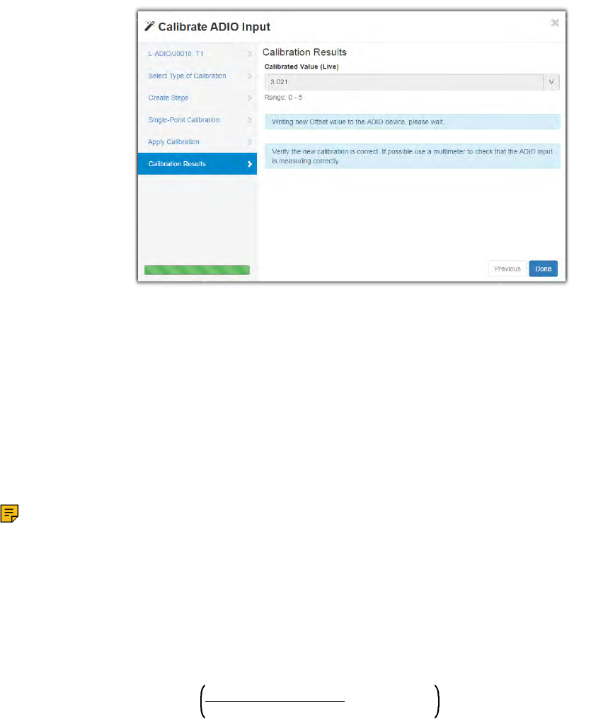
Cordex HP Controller Software Manual | 18 - Maintaining Modules
9. Verify that the new Calibrated Value matches the digital voltmeter reading. Click Done to close the
Wizard.
18.1.4. Calibrating Shunts, Current Transducers and Temperature Probes
This section covers the calibration of shunts, current transducers and temperature probes that are
connected to ADIO inputs.
18.1.4.1. Shunt Calibration
Note: Calibration is considered an expert task.
To calibrate a shunt correctly, you need hardware to generate and measure the input signal accurately.
This topic covers how to do a Single-Point Calibration. If you need to do a Slope/Offset Calibration or
a Two-Point Calibration, a factory calibration document should be written showing, step-by-step, how
both the hardware and the software need to be used to perform an accurate calibration.
A shunt Current reading is calculated as follows:
Current
(
A
)
=
ADIO
Current
Input
Reading
(
mV
)
Range
in
Millivolts
(
mV
)
×
Range
in
Amps
(
A
)
+
Offset
(
A
)
To perform a Single-Point Calibration on a Shunt:
1. Go to System > Inventory > Shunts and click the more details icon to select one of the available
shunts.
0350058-J0 Rev AD Page 223

Cordex HP Controller Software Manual | 18 - Maintaining Modules
2. Set the Offset to zero.
3. Measure the actual current flowing in amps. It may be easiest to do this measurement at 0.0
amps.
4. Record the measured value: ____________ A.
5. Subtract the displayed value: ____________ A, from the Web interface.
6. Calculate the new offset: _____________ A. Offset = Measured Value - Displayed Value.
7. Click the edit icon of the Offset field. Enter the new offset in amps and click Save.
8. Verify that the Offset field was updated, and that the new displayed value matches the
measured value.
18.1.4.2. Current Transducer Calibration
Note: Calibration is considered an expert task.
To calibrate a current transducer correctly, you need hardware to generate and measure the input signal
accurately.
This topic covers how to do a Single-Point Calibration. If you need to do a Slope/Offset Calibration or
a Two-Point Calibration, a factory calibration document should be written showing, step-by-step, how
both the hardware and the software need to be used to perform an accurate calibration.
A current transducer Current reading is calculated as follows:
Current
(
A
)
=
ADIO
CT
Input
Reading
(
V
)
CT
Range
in
Volts
(
V
)
×
CT
Range
in
Amps
(
A
)
+
CT Offset
(
A
)
To perform a Single-Point Calibration on a Current Transducer:
1. Go to System > Inventory > Current Transducers and select one of the available current
transducers by clicking the more details icon.
Page 224 0350058-J0 Rev AD

Cordex HP Controller Software Manual | 18 - Maintaining Modules
2. Set the Offset to zero.
3. Measure the actual current flowing in amps. It may be easiest to do this measurement at 0.0 amps.
4. Record the measured value: ____________ A.
5. Subtract the displayed value: ____________ A, from the Web interface.
6. Calculate the new offset: _____________ A. Offset = Measured Value - Displayed Value
7. Click the edit icon of the Offset field. Enter the new offset in amps and click Save.
8. Verify that the Offset field was updated, and that the new displayed value matches the measured
value.
18.1.4.3. Temperature Probe Calibration
Note: Calibration is considered an expert task.
To calibrate a temperature probe correctly, you need hardware to generate and measure the input signal
accurately.
This topic covers how to do a Single-Point Calibration. If you need to do a Slope/Offset Calibration or
a Two-Point Calibration, a factory calibration document should be written showing, step-by-step, how
both the hardware and the software need to be used to perform an accurate calibration.
A temperature probe Temperature default calculation is as follows:
Temperature
(°
C
)
= Voltage
− 2.73)
(
× 100
Temperature
(°
F
)
= (Voltage
− 2.73) × 180 + 32
To perform a Single-Point Calibration on a Temperature Probe:
1. Go to Modules > ADIO by click the more details icon to select one of the available Temperature
Inputs.
0350058-J0 Rev AD Page 225

Cordex HP Controller Software Manual | 18 - Maintaining Modules
2. Set the Calculation Offset to zero.
Do not confuse Calibration Offset with Calculation Offset. You should only read and change
values in the table labeled Temperature Probe.
Setting the offset to zero will make the temperature reading very high and may cause temperature
compensation and other temperature alarms to activate.
3. Measure the actual temperature at the probe.
4. Record the measured value: ____________ °C or °F.
5. Subtract the displayed value: ____________ °C of °F, from the Web interface.
6. Calculate the new offset: _____________ °C or °F. Calculation Offset = Measured Value -
Displayed Value
7. Click the edit icon of the Offset field. Enter the new offset in degrees and click Save.
8. Verify that the Offset field was updated, and that the new displayed value matches the measured
value.
18.1.5. Testing Relays
To test relays:
1. Go to Modules and click the more details icon of the device to be tested.
2. From the Relays table, click the Test Relay button of the selected relay.
3. If the relay is in and energized state it will become de-energized for one minute. If it is de-
energized, it will be energized during the test. To end the test early, press the Stop Test button.
4. Relays can also be tested by going to the individual relay menu.
Page 226 0350058-J0 Rev AD

Cordex HP Controller Software Manual | 18 - Maintaining Modules
18.1.6. Testing Comms Lost Action
To test the Comms Lost Action function:
1. Go to Modules and click the more details icon of the device to be tested.
2. From the Relays table, click the more details icons of the relay to be configured for the Comms
Lost Action.
3. Ensure the relay’s normal position is set to Energized.
4. Once configured, go to Controller > Configure Controller > Communications > CAN and
disable each enabled CAN bus.
5. Wait five minutes.
6. After five minutes the relay configured as a comms lost relay will de-energize. Re-enable the CAN
bus(es) and the relay will energize.
Note: The Comms Lost Action is only available on CXC-HP v6.10 and later, and firmware in
the CAN module must have a version that supports this feature.
18.1.7. Enabling Temperature Sensor Failure Alarms
The Temperature Sensor Failure alarm activates if the voltage on the temperature input is below or
above the operating range of the input. If the sensor is unplugged, the voltage will be zero and the alarm
activates. If you accidentally apply bus voltage to the temperature input, the alarm activates.
To enable Temperature Sensor Alarms do the following:
1. Go to Modules and click the more details icon on the device with Temperature Sensors.
2. In the Alarms table there is one alarm for each temperature sensor on the ADIO. Click the more
details icon to enable or disable the alarm for the required sensor.
3. Assign a relay or any other parameters as required.
0350058-J0 Rev AD Page 227

Cordex HP Controller Software Manual | 18 - Maintaining Modules
18.1.8. Ground Fault Detection
The HV-ADIO has a ground fault detection (GFD) feature, under the Modules > HV-ADIO menu in the
Configuration table, which can be enabled or disabled. It is disabled by default.
When disabled, the two related values (GFD Resistance and GFD Current) read Unknown, and no GFD-
related alarms are triggered. These values are found under the GFD Information table.
When enabled, the resistance and current across the GFD circuit is reported under the GFD Information
table. There are two alarms related to the GFD located in the Alarms table of the HV-ADIO.
• Ground Fault Resistance Low alarm will be raised if the resistance is lower than the configurable
threshold, which is 20000 ohms by default.
• Ground Fault Current High alarm will be raised if the current is higher than the configurable
threshold, which is 1mA by default.
18.2. Module Firmware Upgrades
This section covers how to upgrade the firmware on CAN devices attached to the controller.
18.2.1. Module Firmware Upgrade
To upgrade the firmware on a module, go to Menu > Modules > Firmware Upgrade table from either the
web or the LCD touchscreen.
Figure 98. Module Upgrade Page - web
Page 228 0350058-J0 Rev AD

Cordex HP Controller Software Manual | 18 - Maintaining Modules
Figure 99. Module Upgrade - LCD
18.2.2. Uploading a Firmware File
Uploading a Firmware File from the LCD
From the LCD you can either choose a file uploaded from a USB drive or one from the Local Files folder.
The Local Files menu contains a list of files previously uploaded via the web. Go to Menu > Modules >
Firmware Upgrade > File.
Uploading a Firmware File from the Web
To upgrade a module over the web, the firmware file must be uploaded to the controller first.
1. Go to Modules > Firmware Files, and click Upload Firmware File table.
Figure 100. Firmware Files Table
0350058-J0 Rev AD Page 229

Cordex HP Controller Software Manual | 18 - Maintaining Modules
2. An Upload File dialog displays.
3. Click the Select File and choose the file to upload. Once a firmware file is selected, click the
Upload button.
Figure 101. Upload File Dialog
Once the file is uploaded, the dialog closes. The uploaded file is now visible in the Firmware Files table
and available to upgrade a module.
18.2.3. Selecting the File to Upgrade
In the Firmware Upgrade table, there are buttons at the top to start or stop the firmware upgrade. These
buttons are not active until a firmware file is selected. The first three rows of the Firmware Upgrade table
display information about the selected upgrade file.
The rest of the table rows show information about the last upgrade that occurred. In the following Ready
to Start Upgrade figure, the controller has been recently reset and no upgrade history displays.
The File Info field is informational, it displays information about how to proceed with an upgrade. Before a
file is selected it displays the message, Select a Firmware (ACAN) File.
The File field is used to select a file for the upgrade. From the web, the upgrade file must be chosen from
those previously uploaded to the controller. On the LCD, you can select either from the list of previously
uploaded files (Local Files), or from a USB drive.
Once a file is selected, the first three rows of the table are updated with new status. If the file chosen
is not a valid upgrade file, or if there are no modules to which that file can be applied, the number of
Modules Compatible With File will be 0, and the File Info field will say, Select a Different Firmware
File.
If the file is valid and applicable to your modules the Modules Compatible With File field will display
how many devices need to be upgraded, and the File Info field will display Ready to Start. If the number
of Modules Compatible With File is smaller that you expected or zero, it may be because some or all
of the modules have already been upgraded to this version. There is no need reload a module with the
same version of firmware. If the firmware is corrupt, the module will detect it and go into a Waiting for
Software state.
Page 230 0350058-J0 Rev AD

Cordex HP Controller Software Manual | 18 - Maintaining Modules
Figure 102. Ready to Start Upgrade
If an upgrade has been completed since the last restart, the bottom rows of the table will still contain
information about that last upgrade until the Start Firmware Upgrade button is pressed.
18.2.4. Upgrading the Module
Once a valid firmware file is uploaded and the File Info field displays, Ready to Start, click Start
Firmware Upgrade.
As the upgrade progresses, the Firmware Upgrade table updates with information about the upgrade.
The Last Upgrade Percent Complete counts up from 0%, and then Last Upgrade Remaining Modules
counts down (if there is more than one module being upgraded).
If there is more than one module being upgraded, the percent complete will show the total (100% will be
reached once all modules are upgraded) instead of a per-module completion.
Figure 103. Upgrade in Progress
0350058-J0 Rev AD Page 231

Cordex HP Controller Software Manual | 18 - Maintaining Modules
The firmware upgrade can be stopped if necessary. If you press Stop Firmware Upgrade button the
controller finishes upgrading the current module so as not to leave it in a non-functional state. If multiple
modules are queued, the next module will not be upgraded.
If the upgrade fails on a module, the controller stops the upgrade and will not attempt to continue on any
further modules that have been queued.
Once the upgrade is finished, the Last Upgrade Percent Complete displays 100%, and the Last
Upgrade Status displays Succeeded.
Figure 104. Upgrade Succeeded
Page 232 0350058-J0 Rev AD

19. Using Custom Views, Data, Timers, Counters,
Scheduler and Custom Actions
This section of the manual covers the following:
• Using Custom Views
• Using Custom Data
• Using Timers
• Using Counters
• Using the Scheduler
• Using Custom Actions
19.1. Using Custom Views
The Custom Views feature allows you to create and customize a unique view. For example, a Custom
View may be created to make a new dashboard view with its own unique components.
Components for a new Dashboard View can include:
• A pre-existing table from the controller or systems
• A new custom table with status and configuration values
• A new custom table with inventory values
Components for a new Custom Data View can include:
• A new custom table with inventory values
19.1.1. Creating Custom Views
To create a Custom Dashboard view:
1. Go to Controller > Configure Controller > User Interface Preferences > Custom Views table.
2. Under the Custom Views tab select either the Add Custom Dashboard View, or Add Custom
Data View button.
3. Click the more details icon to open the Configuration and Components tables.
4. In the Configuration table, give your new Custom View a name and description.
19.1.2. Adding Components in the Custom View
The Components table has three buttons: Add Existing Table, Add Custom Table with Status and
Configuration, and Add Custom Table with Inventory.
Note: Depending on the type of view you choose, not all the component options will be available.
0350058-J0 Rev AD Page 233

Cordex HP Controller Software Manual | 19 - Using Custom Views, Data, Timers, Counters, Scheduler and Custom Actions
Figure 105. Components Table in the Custom Dashboard View
The Add Existing Table option allows you to add tables from the controller or its systems.
The Add Custom Table with Status and Configuration” or Add Custom Table with Inventorywill add
a new row entry in the Components table.
Note: Components will not display in the order that they were added. Tables will display in the
following order: Existing Tables, Custom Tables with Status and Configuration, Custom Tables with
Inventory.
19.1.2.1. Add an Existing Table to Custom View
The Add Existing Table wizard allows a user to add table(s) from the controller or its systems. These
table(s) are then displayed in the Custom View.
To add an existing table to the custom view:
1. Click the Add Existing Table button within the Components table to launch the wizard.
2. In the Select Table Source window, select the source of the table. Click Next.
3. In the Select Tables window, select the tables that will be added into the components table for the
Custom View. Click Next.
Note: Not all tables will be visible. If values from levels lower than what is visible are required,
it is recommended to create a Custom Table component.
4. Review your selections. Click Next.
5. The Results page notify you that your components have been successfully added. Click Done.
19.1.2.2. Add Custom Table with Status and Configuration
A Custom Table with Status and Configuration allows a user to create a table which displays status or
configuration values from the controller.
To add status and configuration values to a table:
Page 234 0350058-J0 Rev AD

Cordex HP Controller Software Manual | 19 - Using Custom Views, Data, Timers, Counters, Scheduler and Custom Actions
1. Click the Add Custom Table with Status and Configuration button within the Components table
to create a custom table.
2. Click the more details icon on the newly created table.
3. Click the Configure Custom Tables button to launch the configuration wizard.
4. Follow the Configure Custom Table wizard until complete.
19.1.2.3. Add Custom Table with Inventory
A Custom Table with Inventory allows a user to create a table which displays inventory values from the
controller. This table allows for smaller groupings of the same type of item. For example, a user may want
to only view ten custom data items from a list of over 100.
To add inventory values to a table:
1. Click the Add Custom Table with Inventory button within the Components table to create a
custom table.
2. Click the more details icon on the newly created table.
3. Click the Configure Custom Tables button to launch the configuration wizard.
4. Follow the Configure Custom Table wizard until complete.
Note: Only the same type of inventory can be added to this custom table. For example, Delay
Timers and Interval Timers can be added into this table, but Counters or Custom Data cannot.
19.1.3. Accessing and Configuring the Default Custom Dashboard View
Accessing a Custom Dashboard View
All Custom Dashboard Views can be accessed via the navigation bar on the web interface. Custom
Dashboard Views can be accessed and selected in under the Dashboard drop-down.
Configuring a Default Custom Dashboard View
A user may configure one dashboard as the default dashboard. The selected dashboard will be displayed
when the Dashboard menu button is clicked.
The default dashboard selection can be made under Controller > Configure Controller > User
Interface Preferences. Under Default Dashboard you can select the value.
19.1.4. Accessing the Custom Data View
Once you have created Custom Data you may select to view only this Custom Data View.
To select your Custom Data View:
1. Go to Controller > Advanced Functions > Custom Data.
2. In the top right-hand corner you will find a dropdown. Choose your newly created custom data
view.
3. At any point you may choose All Custom Data to return to the default display settings.
0350058-J0 Rev AD Page 235
Cordex HP Controller Software Manual | 19 - Using Custom Views, Data, Timers, Counters, Scheduler and Custom Actions
19.1.5. Removing a Table from the Custom View
Your Custom View may reference a table from a system that has been deleted.
To remove this table:
1. In the Custom View, make note of the name of the table from the deleted system.
2. Go to Controller > User Interface > Preferences > Custom Views table and navigate into the
Custom View associated with the issue.
3. In the Components table, locate the table name from the deleted system.
4. In the Actions column of the Components table, click Remove.
Going back to the Custom View, the table will no longer be visible.
19.1.6. Add an Existing Table to the Custom View
Your Custom View may reference a table from a system that has been deleted.
To re-add and existing table:
1. Re-instate the previously deleted system to the controller.
2. Go to Controller > Configure Controller > User Interface Preferences > Custom Views and
navigate into the Custom View.
3. Click the more details icon.
4. In the Components table, run the Add Existing Table wizard to add the required table that was
unlinked/missing.
19.2. Using Custom Data
The Custom Data feature allows you to create complex expressions that can be used to:
• Provide flexible ways to monitor and control a system
• Create custom conditions for user alarms and relay control
Custom data can be used to calculate values that represent voltages, digital inputs or currents in the
system.
For example, in a system that has multiple load shunts, custom data can be used to sum all the shunt
currents, and then the custom data result can be mapped to a single-load inventory item in a DC system.
Custom data can also be used as the input condition for a user alarm that allows for custom control of
relay outputs on ADIO devices.
19.2.1. Configuring Custom Data
Custom data has three configuration fields:
• Name
• Description
Page 236 0350058-J0 Rev AD
Cordex HP Controller Software Manual | 19 - Using Custom Views, Data, Timers, Counters, Scheduler and Custom Actions
• Equation
There are also fields to help troubleshoot and fix equations that are not parsing correctly:
• Custom Data Status, Error Position, Error Token and Expected Token.
These fields provide hints to potential equation parsing errors. There is also a Result field that displays
the result of the parsed equation. The Result field may show a number with up to six decimal places, if
the value is numeric. Results of a boolean expression will show the conventional representation of True
as 1.000000 and False as 0.000000.
Custom data can be configured via the web or the LCD. The LCD does not support creating of equations,
but you can configure the Name and Description.
The custom data Equation field is constructed from a combination of operators, numbers, variables and
functions. Counters and Timers are also supported and are described in a separate section.
Operators
Custom data supports the following arithmetic and logical operations:
• Add “+”
• Subtract "-"
• Divide "/"
• Multiply "*"
• AND "&"
• OR "|"
• Less than "<"
• Greater than ">"
• Equal "="
• Parenthesis "(" and ")"
• Unary minus "-"
Number Formats
Custom data supports the following formats for numbers:
• Decimal: “10.33” or “- 4.7” or “0.45” or “.45”
• Integer: “10” or “-4”
Variables
There are two kinds of variables: numeric and state.
Numeric variables can be used for:
• ADIO voltage, shunt, temperature
0350058-J0 Rev AD Page 237

Cordex HP Controller Software Manual | 19 - Using Custom Views, Data, Timers, Counters, Scheduler and Custom Actions
Note: When using any temperature value as a variable, the value shown in the Variables
table may appear in units of Celsius or Fahrenheit depending on the selected language. However,
when the variable is used in the custom data equation it will always be evaluated using the internal
representation in units of Celsius. If the calculations must be done in units of Fahrenheit it is
necessary to explicitly convert the value in the equation itself. For example, if the variable is named
"T" and is showing as "71.3°F", then the equation should use "(T*1.8+32)" instead of just "T". This
will convert the Celsius value of "21.8" to the Fahrenheit value.
• System values including Total Load Current, Time Remaining in Equalize
Note: Some time-spans such as Time Remaining in Equalize may appear in the format
"d h m s" rather than in decimal form. In this case, the time unit used to evaluate the custom data
equation will be shown in the selection panel when choosing the numeric variable’s Field source;
the unit will be shown in parenthesis. For example, if the variable value shows as “1h 10m (m)”,
then the equation will be calculated using 70 minutes.
• System inventory values including Load Breaker/Fuse, Countdown to LVD, Load Disconnect
• Rectifier group values including Estimated AC Mains Voltage, Total Output Power, Number of
Failed Rectifiers
• Converter group values including Total Installed Capacity, Number of Acquired Converters
• Counter and Timer values including, Counter Output, Delay Time Remaining
• Other Custom Data
State variables can be used for:
• Alarms states (active, disabled, acknowledged, etc)
• Battery Modes (charging, discharging, conditioning, etc)
• Charging states (idle, active, etc)
• Breaker states (open, closed)
• Digital inputs (active, inactive)
• Disconnect states (active, inhibited, pending, inactive, etc)
A state variable compares the live value of a state field to up to four of its possible values. The possible
values are called “True If” values since the state variable will evaluate to True if the state field matches
any of the possible values.
Note: State variables will always evaluate to True or False. A state variable should always be used
with a value that represents a state. Numeric values should not be used when creating a state variable.
Tips on using variables:
• The keywords “True” and “False” can also be used in an equation. They are treated as built-in
variables that represent the value of one and zero.
• Variables are created within the context of a single unique instance of Custom Data. A variable
created for use in a specific Custom Data equation cannot be reused in another equation.
Page 238 0350058-J0 Rev AD
Cordex HP Controller Software Manual | 19 - Using Custom Views, Data, Timers, Counters, Scheduler and Custom Actions
• Variable names must adhere to a specific format. The name must start with a letter, followed
by letters, digits or underscores. Some valid names are “T1”, “T_1”, “Vbat”, “BatteryCurrent”,
“Load_2_Current”
• Short but meaningful names offer the best readability when used in an equation.
Once Custom Data has been created it can be used throughout the controller and systems as input to
various configurations.
For example, in a User Alarm all Custom Data displays in the selection list of the Source field. You can
use this Custom Data to alarm and control relays based on any custom parameters required.
Another example is configuration for a load. The Load Current Source field displays all Custom Data so
you can sum multiple currents to represent the load current.
Generally, any Source field that allows you select inputs will also provide all Custom Data as an option.
Functions
There are three supported functions: abs(), sqrt(), power(). The abs() and sqrt() accept a single input
parameter, and the power() accepts two parameters. For the power() function, the first parameter is the
base and the second parameter is the exponent. For example, power(2,3) would evaluate to 8.
19.2.2. Creating Custom Data
Creating custom data can be challenging, depending on the complexity of the equation required. The
following section describes a basic work flow that applies to all custom data, followed by a more detailed
work flow for how to create an equation with multiple variables.
Finally, there are two examples provided: one for summing shunt readings for a load, and a second for
creating a user alarm to detect if an air conditioning unit in a room is set too low.
19.2.3. Creating Custom Data - Basic Work Flow
The basic work flow for custom data is the same, regardless of what kind custom data is being created.
To create new custom data here is the basic work flow:
1. Create the new Custom Data.
2. Configure a Name and Description.
3. Create the variables.
4. Enter the equation.
5. Verify that the equation is valid.
6. Test the equation.
19.2.4. Creating Custom Data - Detailed Work Flow
The following steps describe a general, detailed work flow for creating custom data.
1. Go to Controller > Advanced Functions > Custom Data. This table displays all the custom data
available in the controller.
0350058-J0 Rev AD Page 239

Cordex HP Controller Software Manual | 19 - Using Custom Views, Data, Timers, Counters, Scheduler and Custom Actions
2. Press the Add Custom Data button. A new custom data line displays. Click the more details icon.
3. There are two tables: Configuration and Custom Data Variables. The Custom Data Variables
table shows all the variables that have been created for this custom data. Initially it will be empty.
4. In the Configuration table, enter a name and description for your custom data. The description is
optional but a name is highly recommended.
5. In the Custom Data Variables table, click the Add Numeric Variable or Add State Variable
button depending on the type of variable to be used. A new variable line will display, click the more
details icon.
6. From the new Variable table enter: Name, and Description. Give the variable a short, but
meaningful name because this is the name used in the equation.
7. Click the Field edit icon. A selector screen displays (see the following figure). To use the selector,
click an item from the left-most column. A new set of selections displays to the right. Keep clicking
until you have the value needed. Click Save.
Once a field is clicked, the bottom area of the screen displays the name, value and additional
information within the Help text.
8. If this is a state variable, also select up to four “True If” values.
9. Repeat steps 5 through 8 to create as many variables as required.
10. After all variables have been created, click the edit icon for the Equation field on the
Configuration table. Enter the desired equation.
Page 240 0350058-J0 Rev AD

Cordex HP Controller Software Manual | 19 - Using Custom Views, Data, Timers, Counters, Scheduler and Custom Actions
11. Verify that the Custom Data Status field shows Valid. If it does not, use the information provided
to find and fix the error. The Error Position, Error Token and Expected Token may provide
helpful information.
If possible, test the equation to ensure it is providing the expected value.
19.2.5. Custom Data Examples
The following two examples illustrate the process of using Custom Data for summing load shunt currents
and detecting if interior air conditioning is set too low and creating a User Alarm.
19.2.6. Custom Data - Summing Load Shunts
The following example shows how to create custom data that sums up three shunt currents, and maps
the result to the system load inventory item.
1. Use the steps in the detailed work flow to create custom data which sums up three variables to
compute a value for the total load current in a system. When selecting a current reading, it must
be selected from a shunt in the system, not at the ADIO input. It will look something like this when
finished.
0350058-J0 Rev AD Page 241

Cordex HP Controller Software Manual | 19 - Using Custom Views, Data, Timers, Counters, Scheduler and Custom Actions
2. To set up the Load to use this Custom Data, go to System > Inventory > Load, click the more
details icon for the Load that will represent the sum of the three shunts.
3. In the Configuration table, click to edit the Load Current Source field, and then use the drop-
down menu to select the Custom Data Result. The image below shows how the custom data
displays in the menu.
4. The Load Current Source field in the Configuration table displays the information as in the
following figure.
Page 242 0350058-J0 Rev AD

Cordex HP Controller Software Manual | 19 - Using Custom Views, Data, Timers, Counters, Scheduler and Custom Actions
Figure 106. Custom Data Load Current Shunts
5. When configured, the custom data that sums the load current will look similar to the figure in step
1.
The load current now correctly shows the sum of the three shunts.
19.2.7. Custom Data - AC Cooling too Low User Alarm
The following example shows how to create a User Alarm that is active if it appears that the air
conditioning in the room is set too low.
1. Use the steps in the detailed work flow to create custom data that has an equation which evaluates
to “true” if the outdoor temperature is greater than 25°C, if the outdoor temperature is greater
than the indoor temperature, and if the difference is greater than 5°C. When finished, it will look
something like this.
2. To set up a User Alarm to use this Custom Data, go to Controller > Advanced Functions >
User Alarms.
3. Select Add Digital User Alarm, and click the more details icon to edit the alarm details.
4. Configure the alarm name, relay and any other information required.
0350058-J0 Rev AD Page 243

Cordex HP Controller Software Manual | 19 - Using Custom Views, Data, Timers, Counters, Scheduler and Custom Actions
5. In the Configuration table, click the edit icon on the Source line, and then select the Custom
Data created to detect if air conditioning is set too low. Click Save. The custom data will display in
the drop-down list something like this:
6. The User Alarm configuration for the Source field should look like the following image.
The User Alarm activates if the indoor temperature is too low as compared to the outdoor temperature.
19.3. Using Timers
Using the Timers feature you create two types of timers: a delay timer or an interval timer.
• The Delay Timer can be used with Custom Data to produce a programmable delay when a
certain event happens.
• The Interval Timer can be used with Custom data to measure the time between two events.
Note: An event is defined as a boolean expression that transitions from false to true or not unknown
to true. Since some logical conditions can evaluate to unknown, for example when data cannot be
retrieved from a CAN module, it is important to construct events so that they always transition from false
to true.
Page 244 0350058-J0 Rev AD

Cordex HP Controller Software Manual | 19 - Using Custom Views, Data, Timers, Counters, Scheduler and Custom Actions
For example, a Delay Timer might be configured to delay the start of a generator once the voltage falls
below a certain value. An Interval Timer might be used to measure how many generator restarts occur in
a 24-hour period.
19.3.1. Configuring the Delay Timer
A Delay Timer has eight configuration fields:
• Name
• Description
• Delay: the amount of time for the timer delay.
• Auto Reset: when enabled, the timer is stopped and the output is set to False
• Output True When: determines when the timer output is True - When Running or When Delay
Over
• Retrigger: when enabled, the timer can be continuously re-triggered when the Trigger goes
from false to true before the delay time elapses. When the timer is re-triggered, the Delay Time
Remaining starts counting down again from the configured delay time and the output will stay true.
• Trigger Source: the field that represents the Trigger value. It is usually set to the result of a
custom data.
• Reset Source: an optional field that represents the Reset value. It is usually set to the result of a
custom data.
There are also fields to describe the state of the Delay Timer:
• Output: this value will be true when the timer is on and the delay is active.
• Delay Time Remaining: the number of seconds remaining in the delay.
• Trigger: the value of the timer trigger. When this value goes from false to true, the delay timer
starts and the output goes true as long as the Reset value is false.
• Reset: the value of the timer reset. When this value is true, the timer output will be false.
The Reinitialize Timer button can be used if the timer configuration has been changed while the timer is
active.
Note: It is also possible to test the timer or force it into a desired state using the Force Timer to
Start and Force Timer to End buttons, even if Start Event has not been configured.
• Force Timer to Start simulates the Start Event going from false to true.
• Force Timer to End sets the Delay Time Remaining going to zero and the timer going into its
terminal state.
Delay Timer Operation
The Delay Timer operates as follows:
0350058-J0 Rev AD Page 245

Cordex HP Controller Software Manual | 19 - Using Custom Views, Data, Timers, Counters, Scheduler and Custom Actions
• When the Reset is true, or if Auto Reset is enabled and the timer trigger source is false, the timer
output is always false and the Delay Time Remaining is set to the initial value.
• When Output True When value is When Running and the Trigger input goes from false to true,
the Output goes true and the Delay Time Remaining starts counting down from the delay value.
• When Output True When value is When Delay Over and the Trigger input goes from false to
true, the Delay Time Remaining begins counting down and when it reaches 0, the Output goes
true.
• If the timer is actively counting down seconds, and the Output is true when the Trigger input goes
from false to true, the timer starts counting down seconds starting from the configured delay time
for as long as the Retrigger is enabled.
• When the Reinitialize Button is pressed, the timer Output will be set false and the Delay Time
Remaining is set to the initial value.
19.3.2. Configuring the Interval Timer
An interval timer has four configuration fields:
• Name
• Description
• Start Event Source: the field that represents the timer Start Event. It is usually set to the result of
a custom data.
• Stop Event Source: the field that represents the timer Stop Event. It is usually set to the result of
a custom data.
There are also fields to describe the state of the Interval Timer:
• Output: the output of the timer in seconds.
• Start Event: the present value of the Start Event field. It will evaluate to true or false.
• Stop Event: the present value of the Stop Event field. It will evaluate to true or false.
The Reinitialize Timer button can be used if the timer configuration has been changed while the timer is
active.
Note: It is also possible to test the timer or force it into a desired state using the Force Timer to
Start and Force Timer to End buttons even if Start Event and Stop Event have not been configured.
• Force Timer to Start simulates the Start Event going from false to true.
• Force Timer to End simulates the Stop Event going from false to true.
Interval Timer Operation
The interval timer operates as follows:
• When Start Event goes from false to true, the timer Output begins incrementing seconds starting
from 0.
Page 246 0350058-J0 Rev AD

Cordex HP Controller Software Manual | 19 - Using Custom Views, Data, Timers, Counters, Scheduler and Custom Actions
• When Stop Event goes from false to true, the timer Output stops incrementing seconds and
remains at the value it had at the Stop Event time.
• If the timer is incrementing seconds, and the Start Event goes false to true again, the Output
starts incrementing seconds starting from 0.
• When the Reinitialize Button is pressed, the timer Output will be set to ‘---’.
19.4. Using Counters
The Counters feature makes it possible to create an Up Counter or a Down Counter that keeps track of
events. A counter can be used with Custom Data as a variable in an equation.
Note: An event is defined as a boolean expression that transitions from false to true.
For example, an Up Counter might be configured to increment whenever the battery voltage goes below
a certain value to count the number of discharges that have occurred.
19.4.1. Configuring the Up Counter
An Up Counter has five configuration fields:
• Name
• Description
• Input Source: the field that represents the Input value. It is usually set to the result of a custom
data.
• Reset Source: this optional field represents the Reset value. It is usually set to the result of a
custom data.
• Terminal Value: this is an optional numeric value that is the maximum value.
There are also fields to describe the state of the counter:
• Input: the value of the field that was selected for the Input Source. It will evaluate to false or true.
• Output: the value of the counter.
• Reset: the value of the field that was selected for the Reset Source. It will evaluate to false or true
• Terminal Reached: this value is true when the counter Output is equal to the Terminal Value.
The counter also has a Reinitialize Counter button. When this button is pressed, the counter Output is
set back to zero.
Up Counter Operation
The Up Counter operates as follows:
• When the Input value goes from false to true, the Output will increment by one, as long as it is
less than the terminal value and the Reset value is false.
• When the Reset value is true, the Output will always be zero.
• The Terminal Reached value will be true whenever the Output is equal to the Terminal Value.
0350058-J0 Rev AD Page 247
Cordex HP Controller Software Manual | 19 - Using Custom Views, Data, Timers, Counters, Scheduler and Custom Actions
• When the Reinitialize Counter button is pressed, the counter Output is set to zero. This allows for
a manual reset of the counter in case the Reset Source has not been configured.
19.4.2. Configuring the Down Counter
A Down Counter has five configuration fields:
• Name
• Description
• Input Source: the field that represents the Input value. It is usually set to the result of a custom
data.
• Initialize Source: this optional field is used to represent the Initialize value. It is usually set to the
result of a custom data.
• Initial Value: the initial value of the Down Counter.
There are also some fields to describe the state of the counter:
• Input: the value of the field that was selected for the Input Source. It will evaluate to false or true.
• Output: the value of the counter.
• Initialize: the value of the field that was selected for the Initialize Source. It will evaluate to false
or true.
• Counter at Zero: this value is true when the counter Output is equal to zero
The counter also has a Reinitialize Counter button. When this button is pressed, the counter Output is
set back to the initial value.
Down Counter Operation
The down counter operates as follows:
• When the Input value goes from false to true, the Output will decrement by one, as long as it is
greater than zero and the Initialize value is false.
• When the Initialize value is true, the Output will always be equal to the Initial Value.
• The Counter at Zero value will be true whenever the Output is equal to zero.
• When the Reinitialize Counter button is pressed, the counter Output is set to the Initial
Value. This allows for a manual reset of the counter in case the Initialize Source has not been
configured.
19.5. Using Scheduler
The Scheduler feature makes it possible to create actions which can occur or recur at specific times or
dates. With this feature you can:
• Schedule a single action
• schedule a recurring action, hourly, daily, weekly or monthly
Page 248 0350058-J0 Rev AD

Cordex HP Controller Software Manual | 19 - Using Custom Views, Data, Timers, Counters, Scheduler and Custom Actions
The Scheduler can be used to do the following:
• Equalize the batteries on a DC system
• Run a battery test on a DC system
• Put a DC system back into float mode (canceling any equalize or battery test)
Note: Equalize or Battery Test have user configurable termination conditions in their menu settings,
therefore it is generally not necessary to schedule an end within Scheduler.
19.5.1. Configuring a Recurring Action
To create a recurring action:
1. Go to Controller > Advanced Functions > Scheduler. A table displays available options.
2. Press the Create Scheduled Action button to launch the wizard.
3. Follow the instructions to set up the schedule type, start date and time, recurrence interval, Actions
and an end condition if required.
The table displays the new Scheduled Action, and when that action will run.
0350058-J0 Rev AD Page 249

Cordex HP Controller Software Manual | 19 - Using Custom Views, Data, Timers, Counters, Scheduler and Custom Actions
A Scheduled Action can also be triggered manually by clicking Trigger Action Manually. This is
intended to be used for testing during configuration.
19.6. Configuring a One-Time Action
To create a one-time scheduled action:
1. Go to Controller > Advanced Functions > Scheduler . A table displays available options.
2. Press the Create Scheduled Action button to launch the wizard.
3. Follow the instructions to set up the One Time, Scheduled type, and the Action to be performed.
The table displays the new Scheduled Action and when that action will run.
Page 250 0350058-J0 Rev AD

Cordex HP Controller Software Manual | 19 - Using Custom Views, Data, Timers, Counters, Scheduler and Custom Actions
19.7. Configuring Scheduled Actions
The controller wizard is used to create and configure scheduled actions, with the exception of the Action
field. The Scheduler has five configuration fields. The first four can only be configured via the wizard.
• Schedule Type - one time, hourly, daily, weekly, monthly
• Start Date and Time - This is the date the event takes place. For recurring events, time is the
specific time of day each event runs (with the exception of hourly events)
• Recurrence Interval - The time between occurrences (every three hours, every six months, etc.)
• End Type - can be set to never end,, end by a date, or end after a certain number of occurrences
• Action - the specific action that runs at each interval
0350058-J0 Rev AD Page 251

Cordex HP Controller Software Manual | 19 - Using Custom Views, Data, Timers, Counters, Scheduler and Custom Actions
Figure 107. Scheduler Wizard
Additional fields describe the state of a scheduled action:
• Recurrence - A message describing when and how ofter an action will occur.
• End - a message detailing when a recurring actions will end.
• Scheduled Status - A message describing either “waiting”, “completed” or “missed”
• Last Run - The time the last action ran
• Next Scheduled Run - The time the next action will run
• Total Executed Runs - The total number of times this scheduled action has run
In addition to the information listed in the fields, the Event Log will contain a message each time an action
has run or been missed.
Note: In situations where the controller has been off and Daylight Savings Time occurs, the
Scheduler runs actions up to one-hour after they are scheduled to run. For example: if an action is
scheduled for a single occurrence, at 9/1/2017 4:00PM, and the controller is off at 3:30 PM and back on
at 4:30PM, then the scheduled action will still run.
19.8. Using Scheduled Time Spans
The Scheduled Time Span is used to create a daily time span using custom data, or other features that
can take a boolean input (true or false, yes or no).
Using the Scheduled Time Span, you can configure the following:
• A name for easy identification. For example, “Morning Rush Hour”.
• A start time and end time.
Page 252 0350058-J0 Rev AD
Cordex HP Controller Software Manual | 19 - Using Custom Views, Data, Timers, Counters, Scheduler and Custom Actions
• A scheduled date range, such as, on all days, on weekdays only, or on weekends only.
Once configured, the Scheduled Time Span outputs a boolean signal called Within Time Span. This
value is true if the current time is within the time span, and false otherwise.
This boolean signal can be used in custom data to indicated whether or not the controller is operating
within a given time span. One example is to create a custom data equation that would only be evaluated
during certain periods of the day, or conversely, not evaluated during certain periods of the day.
19.9. Using Custom Actions
The Custom Action feature makes it possible to change a relay or field to different values based on a
condition. With this feature you can:
• Activate/deactivate a relay based on a condition
• Change the value of a numeric configuration field based on a condition
• Change the value of a numeric configuration field to the value of a Custom Data
19.9.1. Configuring a Change Relay Action
Change Relay actions can be used to control equipment, external to the system, based on specific
conditions. For example, in a case where external equipment should be turned on or off based on the
state of the controller (i.e. turn a generator on when AC is lost). In this specific example, the condition
would be to check if power has been lost, if yes, then the Relay To Change would activate, turning on the
generator. To access this feature go to Controller > Advanced Functions > Custom Data.
A Change Relay action has four configuration fields:
• Name
• Description
• Relay To Change: the relay that will be changing based on the specified condition
• Condition: a boolean field that will control the relay
There are also fields that describe the state of the action:
• Field Value When Condition True: what state the relay will be in when Condition Value is true
• Field Value When Condition False Or ---: what state the relay will be in when Condition Value is
false or unknown
• Condition Value: the present value of Condition
• Field Value: the present value of Relay To Change
Change Relay Action Operation
The Change Relay action operates as follows:
• When the Condition Value is false or unknown, the relay will be in its normal state.
• When the Condition Value is true, the relay will be in its abnormal state.
0350058-J0 Rev AD Page 253
Cordex HP Controller Software Manual | 19 - Using Custom Views, Data, Timers, Counters, Scheduler and Custom Actions
19.9.2. Configuring a Change Field To Constant Action
The Change Field To Constant action feature can be used to change the value of a field based on
specific situations. This can be useful to control the state of the system based on external conditions. For
example, when a generator is on, the system can be set to charge the batteries at a lower rate so that it
does not drain the generator.
To access this feature go to Controller > Advanced Functions > Custom Data.
A Change Field To Constant action has six configuration fields:
• Name
• Description
• Field To Change: the field that will be changing based on the specified condition
• Condition: a boolean field that will cause Field To Change to change to different values
• Field Value When Condition True: the value of Field To Change when Condition Value is true
• Field Value When Condition False Or ---: the value of Field To Change when Condition Value
is false or unknown
There are also fields that describe the state of the action:
• Condition Value: the present value of Condition
• Field Value: the present value of Field To Change
Change Field To Constant Action Operation
The Change Field To Constant action operates as follows:
• When the Condition Value is false or unknown, Field To Change will be set to Field Value When
Condition True
• When the Condition Value is true, Field To Change will be set to Field Value When Condition
False Or ---
19.9.2.1. To Configure a Change Field To Constant Action
One way to use a Change Field To Constant Action is to set Auto DC Priority. The following describes
how to configure a Change Field Action To Constant to control the amount of power the Inverter
System takes from DC, based on the time of day.
Go to System > Inverter System > System Functions and in the Manual DC Priority table, ensure that
Manual DC Mode is Enabled.
1. Go to Controller > Advanced Functions > Scheduler.
2. Click the Create Time Span wizard to select the days and times.
3. Go to Controller > Advanced Functions > Custom Data.
4. Click Add Change Field To Constant Action, and click more details.
Page 254 0350058-J0 Rev AD
Cordex HP Controller Software Manual | 19 - Using Custom Views, Data, Timers, Counters, Scheduler and Custom Actions
5. In the Configuration table, select Field To Change, select the AMPS HP2 system and then
Desired DC Input Power.
6. In the Configuration table, select Condition > Time Span > Within Time Span.
7. In the Configuration table, select Field Value When Condition True and set to 100 %.
This causes the Inverter System to pull all its power from DC during the more expensive hours for
power usage.
8. In the Configuration table, select Field Value When Condition False to 0%.
This causes the Inverter System to pull all its power from AC during cheaper hours of power
usage, allowing the batteries to charge during that time period.
19.9.3. Configuring a Change Field To Variable Action
The Change Field To Variable action feature can be used to change the value of a field to the value of
a Custom Data. This can be useful to control the state of the system based on external conditions. For
example, the rectifier’s power output can be adjusted based on a limit to the amount of AC power that
should be consumed.
To access this feature go to Controller > Advanced Functions > Custom Data.
A Change Field To Variable action has five configuration fields:
• Name
• Description
• Field To Change: the field that will have its value changed to the value of the configured Custom
Data
• Set Field To Custom Data: the value of Field To Change will be set to the value of this Custom
Data
• Field Value Change Interval: the number of seconds between each time the value of Field To
Change will be set to the value of Set Field To Custom Data
There are also fields that describe the state of the action:
• Last Error Condition: describes if there are any errors, either with the configuration or the
operation of this action
• Field Value: the present value of Field To Change
• Field Range: the range for Field To Change. The value of Field To Change will only be set if the
value of the configured Custom Data is within this range
• Custom Data Value: the present value of Set Field To Custom Data
• Time To Next Possible Change: the amount of seconds until the next time Field To Change will
have its value set to the value of the configured Custom Data, if the value is different and within
range
Change Field To Variable Action Operation
The Change Field To Variable action operates as follows:
0350058-J0 Rev AD Page 255
Cordex HP Controller Software Manual | 19 - Using Custom Views, Data, Timers, Counters, Scheduler and Custom Actions
• The value of Field To Change will be set to the value of the Custom Data that Set Field To
Custom Data is configured to use
• This value will be set on an interval based on the value of Field Value Change Interval. For
example, if this field is set to 300 seconds (the default), the value of Field To Change will be set
every 300s
• Field To Change will only be set if the value of the configured Custom Data is different than the
present value of Field To Change, and is within range for this field
Page 256 0350058-J0 Rev AD

20. Troubleshooting
This section of the manual covers the following:
• Troubleshooting the controller
• Troubleshooting the system
20.1. Troubleshooting Your Controller
This section of the manual covers possible issues and fixes for your controller. Also see the readme notes
that ship with the CXC HP software.
20.1.1. No Communication
Check all connection cables.
Check the controller settings via the Controller > Configure Controller > Communications > Ethernet.
Ensure that the controller is configured to communicate via the web. See Getting Started and Setting Up
Controller Communication.
Ensure that both ports in the Ethernet table have the address mode configured correctly.
Note: The default IPv4 configuration for the controller must have the rear Ethernet port set to
automatic (DHCP) and the front Ethernet port set to manual (static).
20.1.2. Unable to Communicate via Ethernet
Confirm that all cables are firmly connected.
1. Go to Controller > Configure Controller > Communications > Ethernet.
2. Ensure that the IP address settings are correct.
3. Edit the settings if required.
4. Click Save.
5. If that does not work, then reset the controller.
CAUTION: Pressing the reset button restarts the controller using the last settings that were
saved.
If the issue is not resolved, contact your IT department to confirm that both the controller and the
computer can communicate across the network.
20.1.3. Home Button or LCD Screen Not Responding
If the controller is not responding to touch or the Home button is not responding to touch, you can perform
a controller reset.
CAUTION: Pressing the reset button does not ensure that the settings are saved.
0350058-J0 Rev AD Page 257
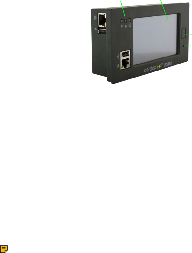
Cordex HP Controller Software Manual | 20 - Troubleshooting
Status LEDs LCD screen
Home
Reset
To perform a hardware reset:
1. From the front of the controller, press the reset button.
20.1.4. Controller Fail
The controller has a relay that can be used to indicate the controller power has failed. This relay is labeled
Alarm and is located beside the power connector. In-shelf versions of the controller do not have this relay.
When the controller is operational, the relay is in the NO position. When the controller power has failed
this relay is in the NC position. If voltage is applied to the power connector and the Alarm relay is in
the NC position and the controller does not start up, it is likely the controller has failed and should be
replaced.
In-shelf controllers (i.e. CXC-HPM1) do not have a dedicated controller fail relay. Failure of an in-shelf
controller may result in relays becoming de-energized. These de-energized relays function as a controller
fail relay.
Note: The controller fail relay is not programmable in any way.
20.1.4.1. FXM-HP Controller Fail
Failure of the controller inside the FXM-HP may not result in any relay becoming de-energized since the
relays are on a separate, independent CAN module.
It is recommended to use the Comms Lost Action setting on the relay details page. If communication
is lost between the internal controller and the FXM-ADIO module, the relay will de-energize five minutes
after communication is lost.
This feature is available in CXC-HP v6.10 and later. The CAN module firmware also needs to be updated
to a version that supports this feature.
Page 258 0350058-J0 Rev AD

Cordex HP Controller Software Manual | 20 - Troubleshooting
20.2. Troubleshooting a Rectifier System
This section of the manual covers possible issues and fixes for your system. Also see the readme notes
that ship with the CXC HP software.
20.2.1. Relays Not Triggered During Alarm Conditions
If the relays are not trigged during alarm conditions try the following:
• Ensure alarm condition is mapped to a relay (Alarms > All Alarm Settings).
• Ensure polarity of the relay is set correctly
• Ensure Cutoff All Alarms had not been selected
• Ensure ADIO is communicating
20.2.2. Rectifier Alarms and Alerts
Alarm: An alarm is a notification of a change to the state of the controller. Alarms can be configured with
thresholds (if applicable), mapped to relays and will trigger SNMP notifications.
Alert: An alert is a notification from a device that indicates a problem or change in state. An alert is not
configurable. The status of an alert is viewable from a device's detailed status page. For example, to view
rectifier alerts go to System > DC System > Inventory > Rectifiers > Status, and click the view details
icon.
Rectifier Minor Alert: indicates a potential minor problem that doesn't pose an immediate risk to the
rectifier's ability to output power.
Rectifier Fail Alert: indicates a problem with the rectifier's ability to output power.
If the system has an active Rectifier Minor or Rectifier Fail alarm, you can find out the source and cause
of the alarm as follows:
1. Go to System > DC System > Inventory > Rectifiers > Status and look at the # Alerts column.
2. Look for a rectifier in the list with more than zero alerts and click the detailed status icon. The page
displays a Rectifier Alerts table listing all possible rectifiers alerts.
3. Sort the table to find the active alerts. Click the more details icon for a description of the alert. This
information should help you troubleshoot the problem.
Note: A common reason for an unexpected Rectifier Fail alert is a very low load or no load resulting
in a Ramp Test Fail/No Output Power alert. It is normal for a rectifier to have this alert active if there is
no load or very low load. If your system normally operates at very low load you can disable the Ramp Test
under System > DC System > Inventory > Rectifiers > Rectifiers Configuration to clear this alert and
prevent it from activating.
20.2.3. Rectifier Not Acquired
Ensure all rectifiers are secured and tightly screwed into the shelf.
0350058-J0 Rev AD Page 259

Cordex HP Controller Software Manual | 20 - Troubleshooting
Ensure CAN cables are securely connected and routed between all necessary shelves, and to the
controller.
Go to System > DC System > Inventory > Rectifiers > Status, and then click Assign in the Modules
Available for Assignment table for the specific rectifier required.
Note: Even if a system is configured to auto-assign devices, once a rectifier has been unassigned
from the system, it must be manually reassigned back into the system. This is necessary to avoid
unintentional auto-assignment. If a device is unassigned using the Forget button, then it will auto-assign
when discovered on the CAN bus.
20.2.4. Rectifier Communication Lost
If one or more rectifiers have lost communication with the controller for more than 10 seconds an alarm
generates. The alarm will clear when communication is restored to all rectifiers.
If rectifier communication is lost, first check the following:
1. Check all CAN cables for breaks or loose connections.
2. Ensure all rectifiers are secured and tightly screwed into the shelves.
3. Go to System > DC System > Inventory > Rectifiers > Alarms.
4. In the alarms table, click more details icon on Rectifier Comms Lost row to see the details.
20.2.5. Replacing a Defective Rectifier
When a rectifier fails and or is permanently removed, the system generates a Rectifier Comms Lost
alarm.
The alarm is cleared by removing the rectifier from the system inventory.
To remove the rectifier from the system inventory do the following:
1. Remove the defective rectifier from the shelf.
2. In the web interface go to System > DC System > Inventory > Rectifiers > Status.
3. Click Forget on the rectifier to be removed and confirm.
4. Place the new rectifier in the shelf.
5. Rectifiers are plug-and-play, but you may still need to map the new rectifier to an AC phase.
6. If the rectifier shows in the Modules Available for Assignment table, instead of in the Status
table, click Assign to assign the new rectifier.
7. Confirm the assignment.
20.2.6. Using Extended Ranges
If your 12, 24 or 48 volt DC system has a battery and rectifier modules that can operate outside of the
normal ranges, you can enable Extended Ranges to allow your DC System to run outside the normal
ranges.
Page 260 0350058-J0 Rev AD

Cordex HP Controller Software Manual | 20 - Troubleshooting
20.2.6.1. Extended Ranges for Battery Testing
Normally, 12, 24 and 48 volt DC Systems have a fairly narrow range of voltages allowed for battery
testing. These voltages are based on what is considered normal for the batteries and what is possible for
the rectifiers. The ranges are set this way to avoid errors when configuring a new system. The 125 and
220 volt DC Systems have a wider range of battery test voltages because there are a wider variety of
battery configurations used with those systems.
1. Go to System > DC System > Configure System. In the Configuration table, change the
Extended Ranges (Advanced) setting from Normal to Extended.
2. Go to System > DC System > Inventory > Rectifiers > Configuration. In the Configuration table,
set the Minimum Test Voltage to the lowest value allowed by your rectifier.
3. Go to System > DC System > System Functions > Battery Test. In the Configuration table, set
the Battery Test Termination Voltage to the voltage you want the battery test to run to.
We strongly recommend that the Battery Test Termination Voltage on the battery test page be at
least 0.5 volts higher than the Minimum Test Voltage on the rectifier configuration page.
20.2.6.2. Extended Ranges for Battery Equalization
Normally, battery equalization is a process designed to de-sulphate a battery’s plates by holding a
controlled overcharge over the period of a few hours. The Extended Ranges option will allow much longer
durations than is generally used for the battery equalization process. This option helps to support systems
with unusual configurations.
CAUTION: Equalization for extended periods can cause excessive gassing and plate damage.
1. Go to System > DC System > Configure System. In the Configuration table, change the
Extended Ranges (Advanced) setting from Normal to Extended.
2. System > DC System > System Functions > Equalize and Boost. In the Equalize table, change
the Equalize Duration setting to the desired time length.
20.2.7. Rectifier Configuration Error
If there is a Configuration Error alarm active, check the rectifier settings.
1. Go to System > DC System > Inventory > Rectifiers > Configuration.
2. Check the OVP threshold. It must be set higher than any system Equalize, Boost, Absorption or
System Voltage settings. The exact margin required depends on the type of rectifiers, but 48V
rectifiers required at least 1V.
3. Check that System Float Voltage, Equalize Voltage, Boost Voltage and the OVP Threshold are set
within the ranges supported by the rectifiers on your site.
4. Try setting rectifier configuration to the defaults.
5. Check the rectifier manual information about setting ranges.
6. Save any changes. It may take several seconds for the changes to take affect.
0350058-J0 Rev AD Page 261
Cordex HP Controller Software Manual | 20 - Troubleshooting
20.2.8. Rediscovering CAN Devices
If all of the installed equipment doesn't display after maintenance it may be caused by defective CAN
bus cables or sequencing of removal and replacement of equipment with the controller powered down
removed.
1. Check that all CAN bus cables are installed and terminated.
2. Power-cycle CAN devices if possible.
3. Update device firmware if needed.
20.2.9. Replacing a Defective ADIO
When an ADIO fails and/or is permanently removed, the system generates an alarm. The alarm is cleared
by removing the device from the inventory. To remove the device from the inventory do the following:
1. Remove the defective ADIO device.
2. Install the new ADIO device and connect all the wires to the same terminals.
3. Go to Modules and click the more details icon in the row of the ADIO being replaced.
4. In the Configuration table, click the edit icon on the row, Replace with Selected ADIO.
5. In the drop-down menu select the new ADIO and click Save.
6. Click the Replace button. The new ADIO is now set up with all the mapping from the old ADIO.
7. Check and update any other configuration parameters where required.
20.2.10. Troubleshooting a Battery Test
Calculations for SOH, SOC, RTR Battery Test algorithm used by the CXCHP are designed to work
with lead acid batteries which have a Peukert exponent between 1.0 and 2.0. Check your battery
manufacturers’ specifications to ensure that the battery is within these constraints. When a battery is new,
and fully charged, a battery test should show the battery to have 100% Estimated State of Charge and
100% or more Estimated Battery Health. If it does not, check and correct the following:
1. Is the Battery properly connected?
a. Check the wiring between the battery, shunts and the rectifiers.
b. Check that the shunts are properly connected and sized.
2. Is the configuration correct?
a. Go to System > System Functions > Battery Runtime and Health Estimation. Confirm
that Battery Estimation is Enabled, the Load Model is correct for your system, and the
Battery LVD value is correct.
b. Go to System > Inventory > Battery. Click the more details icon and confirm that the
Capacity Rating and the Peukert Exponent are correct.
c. Go to System > System Functions > Battery Test. Check that the Battery Test Timeout
is not too short. For the greatest accuracy set it so that the battery reaches an 80% depth of
discharge. Check that the Battery Test Termination Voltage is realistic. It should be LVD +
1Volt: for example, a 24V system would be 22.0V.
3. Did anything unexpected happen during the test?
Page 262 0350058-J0 Rev AD

Cordex HP Controller Software Manual | 20 - Troubleshooting
a. Was the load changed?
b. Did the AC power go out?
c. Was the controller restarted? Go to Controller > Controller Status and check the Time
Since Restart.
4. Is the Battery on Discharge alarm active? During a discharge, it is normal to see the Battery
on Discharge alarm activate. This alarm activates when the battery voltage is below the System
> Inventory > Battery String > Configuration > Open Circuit Voltage value AND the battery
current is below System > Inventory > Battery String > Charging/Discharging Thresholds >
Discharging Threshold value.
If you corrected anything from the above list, allow the batteries to fully recharge (at least 24-hours), and
then run the battery test again. If a battery test shows Estimated Battery Health to be 80% or less the
batteries should be replaced.
20.2.11. Troubleshooting Power Save
If Power Save is either Stopped or Suspended it may be due to the following conditions. Please review
the table below for possible causes and solutions. From the web interface go to System > DC System >
System Functions > Power Save.
Table 5. Troubleshooting Power Save
Issue Possible Cause Solution
Power Save status
is: Stopped - All
Modules Failed, In
Foldback or Un-
supported
Units are not sup-
ported for power
save, high temper-
ature, low AC input
voltage
Replace failed rectifiers.
Wait for temperature to drop.
For universal input rectifiers operating at 120VAC nominal in-
put voltage, power save cannot be used and should be disabled.
These units typically can only be loaded to around 50%, due to
low input voltage derating so power save has no beneficial effect.
Power Save status
is: Stopped - Total
Load Current In-
valid
Incorrect configura-
tion of load current;
lost communication
with rectifiers
Check configuration of loads and shunts.
Restore rectifier communication.
Power Save status
is: Suspended
AC fail or battery
test
Restore AC.
Wait for battery test to complete.
Power Save status
is: Stopped - Sys-
tem Voltage Invalid
ADIO communica-
tion lost or incorrect
system voltage con-
figuration
Check ADIO communication and restore.
Check system voltage configuration.
Power Save status
is: Stopped - Bat-
Battery charge limit
not configured
Configure battery charge current limit.
0350058-J0 Rev AD Page 263

Cordex HP Controller Software Manual | 20 - Troubleshooting
Table 5. Troubleshooting Power Save (continued)
Issue Possible Cause Solution
tery Charge Cur-
rent Limit Invalid
Power Save status
is: Stopped - In-
valid Data
Data essential to
power save cannot
be computed.
Check all of the above.
Not enough modules
are on and/or bat-
tery is discharging
Module Power For
Maximum Efficien-
cy setting is above
the maximum pos-
sible power achiev-
able
Check the values for current and power capacity under Rectifiers
> Configuration . These values limit the maximum output power
achievable by the rectifier and should be set to 100%.
20.3. Troubleshooting an Inverter System
Incorrect System Configuration
If the system has been incorrectly configured with the wrong number of phases, the commissioning
wizard will need to be executed again.
If the number of DC Groups is incorrect, it is likely that some inverters have the incorrect DC group
number. It is possible to fix this by manually changing the DC group number in the details screen of each
inverter.
If the number of shelves per phase is incorrect, it is likely that some inverters have the wrong bay, shelf or
slot ID. It is possible to fix this by manually changing these values in the details screen of each inverter.
The details screen for an inverter can be found at System > Inverter System > Inventory > Inverters >
Status. Click the more details icon for the inverter of interest.
Warning: Executing the commissioning wizard will turn off the inverters and will require them to be
unplugged! The system must be bypassed or the load taken off line.
20.3.1. Wrong Inverter AC Input Group
An inverter's AC input group number is set automatically to the same value as the output phase number.
It may take a minute or two for the number to be reflected on the user interface. If this number seems
incorrect, unplug the inverter, wait for the fan to stop turning and then reinsert it.
20.3.2. Wrong Inverter DC Input Group
The DC input group number is set automatically during commissioning, based on the configured number
of DC groups as well as the slot ID. If this number seems incorrect, it can be changed from the details
screen of the inverter.
Page 264 0350058-J0 Rev AD

Cordex HP Controller Software Manual | 20 - Troubleshooting
20.3.3. T2S Expert Operations
To thoroughly troubleshoot an inverter system, there are some expert operations that a user may need.
Warning: These operations are not normally needed during operation of an inverter system. They
should only be used by qualified technicians or under the guidance of technical support (www.alpha.ca/
support).
These expert operations are:
• Get Configuration File from T2S
• Upload Configuration File to Controller
• Send Uploaded Configuration File to the T2S
• Get Log file from T2S
• Clear History Log
• Turn Off Inverters
• Turn On Inverters
• Configuration Helper
20.3.4. Troubleshooting and Clearing the System Error Alarm
Occasionally the inverter system will activate a System Error alarm. This may happen after momentary
AC outages, breaker trips, false communication problems or other unusual events. The System Error
alarm is a reminder to check the T2S log file. It is recommended to download and view the log file for any
possible problems. Downloading the log file will also clear the alarm.
To check the T2S log file:
1. Determine which T2S is the source of the alarm. Navigate to System > Inverter System > Live
Alerts and look for the Check Log File alarm in the list. Whenever the Check Log File alert is
active, the System Error alarm will also be active. The Check Log File alert will be shown with the
serial number of the T2S that is causing the alert.
2. Go to System > Inverter System > Inventory > T2Ss and click on the details icon of the T2S
identified in the previous step.
3. In the T2S Expert Operations table click the Get Log File from T2S button. This will initiate a
transfer of the log file from the T2S.
4. Once the log file has been received, click Download to save the file to your computer.
5. Open the file and look for any event entries that might indicate a persistent issue. For example,
module failures or communication problems. These problems may indicate the need to replace a
module or inspect communication wiring.
Once the log file has been transferred from the T2S, the System Error alarm will clear.
0350058-J0 Rev AD Page 265
Cordex HP Controller Software Manual | 20 - Troubleshooting
20.3.5. Phase Saturation Alarm
The Phase Saturation alarm indicates that one or more phases are drawing too much power. The alarm
activates when the ratio of actual output power, over the total installed power (excluding redundant
inverters), exceeds the Saturation Alarm Threshold parameter configured on the T2S controller. This
value is normally set to 100%. To verify the threshold value download the T2S configuration:
To check the T2S Saturation Threshold:
1. Go to System > Inverter System > Inventory > T2Ss and click the details icon of the T2S
identified in the previous step.
2. In the T2S Expert Operations table click Get Configuration File from T2S. This will initiate a
transfer of the configuration file from the T2S.
3. Once the file has been received, click Download to save the file to your computer.
4. Open the file in a text editor and search for “Saturation alarm threshold”. The search should find a
line similar to: “;556; ;Saturation alarm threshold ; ;80; ;%; “. The value 80 indicates the threshold is
80%.
5. If required, this value can be changed. The recommended value is 100. Change the value directly
in the text editor and save. Ensure that only the value is changed and the enclosing semi-colons
are preserved.
6. Return to the controller interface and click Upload Configuration File to Controller in the T2S
Expert Operations table.
7. Select the T2S configuration file that was just edited, and then click Upload.
8. In the T2S Expert Operations table, the Send To T2S. Wait for the transfer to complete.
20.4. Troubleshooting a Line Power System
This section describes to how to troubleshoot LP system alarms, overload and transient events.
20.4.1. Resolving Line Power System Alarms
Some of the alarms from the line power system are generated by the LPS modules. These alarms
are Input Voltage High/Low Shutdown, High Temperature Shutdown, Temperature Warning, Module
Connection Error and any alarm with “Channel” in its name. This section describes how to identify the
module causing the alarm.
1. When one of the line power systems mentioned above is active, go to System > Line Power
System > Layout.
2. On the Layout screen look for a module outlined in red, or a channel with the red exclamation
mark icon that signifies a channel alert. The table shows the physical location of the module to help
find it, should it need to be replaced.
3. Click the channel with the alert icon. If the module is outlined in red, but no channels appears to be
in alert, click any channel.
4. The channel details display in another table.
5. Click the link to show the module details.
Page 266 0350058-J0 Rev AD
Cordex HP Controller Software Manual | 20 - Troubleshooting
6. In the Alerts table, sort on the Value column to show all the active alerts at the top. This identifies
all the alerts that are active on the module. Use the help text for the alerts to decide on the
corrective action.
20.4.2. Fan Tray Alarms
The LP System may be installed with one or more optional fan trays. The fan tray is a CAN connected
device that has a Fan Fail alarm associated with it. This section describes how to identify the module
causing the alarm.
1. Go to Alarms > Active Alarms.
2. In the Active Alarms table, find the Fan Fail Alarm and note the name of the fan tray that is
responsible. This confirms the alarm is caused by the fan tray and not some other device.
3. Look for the physical tan tray with the red LED. Repair or replace as required.
20.4.3. Line Power System Overload
If the line power system is overloaded, one or more modules will start flashing the front panel LEDs
yellow. Eventually the input voltage low alarm may be activated if it is configured and enabled.
If this occurs it may be necessary to add more capacity at the input to the LP system, reduce the power
drawn by the remote load or add more line power modules.
20.4.4. Line Power System Transient Events
Depending on circumstances a remote load may experience a brown-out or momentary loss of power.
This is sometimes caused by a channel that has had a transient low output voltage, ground fault or over-
voltage protection shutdown. Since these transients occur too quickly to trigger an alarm they are instead
logged to the module alert log. After a suspected transient event:
1. Go to Logs > Events and Alerts and view the Module Alerts table.
2. In the Search box, type “transient”. The table now shows only the transient events that have
occurred. If the table is empty then no transients were detected.
3. Each entry for a transient event shows the serial number of the module responsible. Note the serial
number.
4. Go to System > Line Power System > Inventory > Line Power Modules and type the serial
number of the module in the Search box. All other modules should now be filtered out leaving only
the module of interest.
5. Use the Locate button to visually identify the module in the rack.
6. Depending on the type of transient event detected, it may be necessary to unplug and insert the
module to ensure it is fully seated, replace the module or check and fix any channel connections.
0350058-J0 Rev AD Page 267

21. CXC HP Reference Guide
The following section is a reference guide for the controller software.
21.1. Modules
This section serves as a reference to the CXC HP modules, see Table 6 (on page 268).
Table 6. Support for CAN Modules
Category Device Name CXC HP Support
ADIO L-ADIO v2.00
ADIO 6I-ADIO v2.00
ADIO Shunt Multiplexer v2.00
1
ADIO I/M1 ADIO v2.20
ADIO PSU ADIO v2.20
ADIO HV-ADIO v3.00
ADIO 8R8D ADIO v3.10
ADIO 4R8D ADIO Not Planned
2
ADIO 12V BCM Not Planned
ADIO 2V BCM Not Planned
ADIO BDFB VI Meter v3.10
ADIO LPS Fan Tray v3.20
ADIO Smart E2 v4.00
Rectifier Cordex HP 250W 12Vdc v2.10
Rectifier Cordex 400W 24Vdc v2.00
Rectifier Cordex 3.1kW 24Vdc v2.00
Rectifier Cordex HP 300W 48Vdc TBD
Rectifier Cordex 650W 48Vdc v2.00
Rectifier Cordex 1kW 48Vdc v2.00
Rectifier Cordex HP 1.2kW 48Vdc v2.00
1. The shunt multiplexer can be monitored by the CXC HP but it cannot be calibrated by the CXC HP.
2. The 4R8D ADIO is not officially supported. If you connect one to the CXC HP, it will show up as an 8D8R ADIO.
All eight digital inputs will function correctly. The first four relays will function correctly and are mapped to the four
physical relays on the 4R8D ADIO.
Page 268 0350058-J0 Rev AD

Cordex HP Controller Software Manual | 21 - CXC HP Reference Guide
Table 6. Support for CAN Modules (continued)
Category Device Name CXC HP Support
Rectifier Cordex 1.8kW 48Vdc v2.00
Rectifier Cordex HP 2.0kW 48Vdc v2.00
Rectifier Cordex HP 2.4kW 48Vdc v2.00
Rectifier Cordex HP 3.0kW 48Vdc v6.00
Rectifier Cordex 3.6kW 48Vdc v2.00
Rectifier Cordex HP 4.0kW 48Vdc v2.00
Rectifier Cordex HP 12kW 48Vdc v2.11
Rectifier Cordex HP 12kW v2 48Vdc v6.00
Rectifier Cordex 3.3kW 65Vdc Not Planned
Rectifier Cordex 1.1kW 125Vdc v3.00
Rectifier Cordex 1.1kW 220Vdc v3.00
Rectifier Cordex 4.4kW 125Vdc v3.00
Rectifier Cordex 4.4kW 220Vdc v3.00
Converter CXDF 24-48/2kW v2.01
Converter CXDF 48-24/2kW v2.01
Sub-controller T2S v3.00
Inverter AIM 1500 TBD
Inverter AIM 2500 v3.00
Inverter TUS v3.10
Line Powering LPS36 v3.20
Line Powering eLimiter+ v3.20
FXM FXM-ADIO v6.00
ADIO XMBS Smart Bypass v6.20
21.2. Communication Ports
There are three sets of ports that are used for controller communication.
• Two Ethernet ports, commonly referred to as the front and rear Ethernet ports.
• Two USB ports, commonly referred to as the front and rear USB ports.
• Two CAN ports, commonly referred to as CAN1 and CAN2.
0350058-J0 Rev AD Page 269

Cordex HP Controller Software Manual | 21 - CXC HP Reference Guide
21.2.1. Ethernet Ports
The Ethernet ports support a standard RJ45 connection and can run at 10 Base-T or 100 Base-T speeds
with auto MDI-X detection (Medium Dependent Interface crossover detection) to eliminate the need for
cross-over cables.
The Ethernet ports support the IPv4 and IPv6 protocols. The IPv4 protocol supports both static IP
(Internet Protocol) and DHCP (Dynamic Host Configuration Protocol) configuration. The IPv6 protocol
will configure a link-local address automatically. Addresses with other scopes are configured by Router
Advertisements (RA). Both the LCD touchscreen, and CXC HP web interface will display the full list of
IPv6 addresses that have been configured for each port.
You can also use IPv6 addresses for outgoing messages including email servers and SNMP destinations.
SNTP does not support IPv6 at this time.
The CXC HP does not register itself with DNS (Domain Name System) servers nor can it be configured to
join a domain or work group. However, the CXC HP is capable of using a DNS server to resolve domain
names if the gateway is set up to allow that.
Warning: While there are two Ethernet ports available on the CXC HP, it is recommended that they
are not both connected to the same network. There is a concern that network management systems and
higher level control systems will see the CXC HP as two devices and get duplicate notifications (e.g.
SNMP traps) for a single device.
21.2.2. USB Ports
The USB ports support a standard, full-size USB host connection.
Only USB Mass Storage (UMS) devices that have been formatted with a FAT32 (File Allocation Table)
file system are fully supported for use in the USB ports. USB drives with the NTFS (New Technology File
System) file system will not work.
USB ports can be disabled to provide enhanced anti-tampering above and beyond the normal local
physical security of a typical installation. When disabled, the no USB device will function when plugged
in and Should this be required, go to Controller > Configure Controller > User Interface Preferences
> User Interface Preferences to disable and enable USB ports. To successfully disable the ports,
first ensure that there are no USB devices plugged in. Failure to do so may prevent a port from being
disabled, as it is in use; a reset or power cycle may be required before another attempt to disable will be
successful. A disabled USB port should provide no power to the plugged in device. If the device has an
LED on it, this may be used to determine if the port is actually disabled.
21.2.3. CAN Ports
Introduction to CAN for the CXC HP
CAN is used by the CXC HP to discover, collect data from, control and configure the power modules and
input/output (ADIO) modules in the power system. The CXC HP has two up to CAN buses, each of which
can control up to 127 power and ADIO modules.
Page 270 0350058-J0 Rev AD

Cordex HP Controller Software Manual | 21 - CXC HP Reference Guide
What is a CAN bus?
A Controller Area Network (CAN) refers to a network of devices that communicate using the CAN serial
protocol to support distributed real-time control. The CAN bus standard was developed by Bosch and Intel
and has been in use since 1990.
How do CAN bus modules communicate?
A CAN bus uses two dedicated wires for communication called CAN high and CAN low. When the
CAN bus is idle, both lines carry 2.5V. When data bits are being transmitted, the CAN high line goes to
3.75V and the CAN low drops to 1.25V, thereby generating a 2.5V difference between the lines. Since
communication relies on a voltage difference between the two bus lines, the CAN bus is insensitive to
inductive spikes, electrical fields or other noise. This makes CAN bus a reliable choice for networked
communications in electrically noisy environments.
Figure 108. CAN Differential Signaling
Volts
3.75
2.5
1.25
Data
1
0
1
Time
CAN Low
CAN High
2.5V
CAN Network Topology
A CAN network uses a twisted pair cable to transmit the differential signals, terminated at both ends with
120 Ohm Resistors.
Figure 109. CAN Network Topology
CAN_H
CAN_L
120 Ohms
120 Ohms
Node n
Node 1
Node 2
What is CAN Power?
CAN power can be supplied through CAN bus. Optionally a power supply for the CAN bus modules can
be arranged separately. The power supply wiring can be either totally separate from the CAN bus lines
using two, two-wire cables or it can be combined with the CAN bus lines into a single four-wire cable.
CAN bus cabling is available from multiple vendors.
0350058-J0 Rev AD Page 271

Cordex HP Controller Software Manual | 21 - CXC HP Reference Guide
How are Alpha CAN Cables Wired?
The CAN connector used by Alpha Technologies is a 6P6C Offset Latch Modular Connector. These
connectors have gender and the male connectors are called plugs and the female connectors are called
jacks. You may also hear these connectors referred to by their Registered Jack (RJ) equivalent: RJ11,
RJ14 and RJ25 are all physically compatible with 6P6C modular connectors. The figure below shows the
CAN pinout for a 6P6C Offset Latch Modular Plug. Pins 1 & 6 are used for CAN power while pins 2 & 4
are used for CAN signaling.
Figure 110. Alpha CAN Connector
1
2
3
4
5
6
1 CAN Ground
2 CAN High
3 Reserved
4 CAN Low
5 Reserved
6 CAN +5V
Are there distance limitations?
The electrical characteristics of a typical CAN bus cable restrict the cable length. Alpha Technologies Ltd.
recommends having no more than one long CAN cable on a CAN bus and to restrict the length of that
long cable to less than 100 meters.
Is the number of nodes (modules) limited?
CAN allows up to 127 modules per bus.
Where can I get more information about CAN?
CAN is specified by the International Standards Organization (ISO) standard ISO 11898.
21.3. Default System Values and Ranges
The following section provides tables of the default values and ranges for supported systems.
21.3.1. 12V System Default Values and Ranges
This section provides a reference table for the default values and ranges for a 12V system.
Table 7. 12V System Default Values
Setting Name Default Minimum Maximum
Allowed Voltage Range 10.5 15.0
Float Voltage 13.5 11.875 14.55
Equalize Voltage 13.75 12.45 15.05
Boost Voltage 13.75 12.45 15.05
Rectifier - Minimum Test Voltage 11.0
Page 272 0350058-J0 Rev AD

Cordex HP Controller Software Manual | 21 - CXC HP Reference Guide
Table 7. 12V System Default Values (continued)
Setting Name Default Minimum Maximum
Safe Voltage 12.85 11.5 14.0
Over Voltage Protection 14.25 12.125 15.75
Absorption Voltage 13.75 12.45 14.75
Absorption Arming Voltage 12.0 10.5 13.25
Temp Comp Max Voltage 13.875 14.5
Temp Comp Min Voltage 13.125 11.875
Battery String Number of Cells 6 1 200
Temp Comp Voltage Warning 0.25 0 0.25
Battery Test Termination Voltage 11.125 11.125 15.0
Output Voltage High Alarm 13.875 10.50 15.00
Output Voltage Very High Alarm 14.125 10.50 15.00
Output Voltage Low Alarm 12.0 10.50 15.00
Output Voltage Very Low Alarm 11.625 9.00 15.00
21.3.2. 24V System Default Values and Ranges
This section provides a reference table for the default values and ranges for a 24V system.
Table 8. 24V System Default Values
Setting Name Default Minimum Maximum
Allowed Voltage Range 21.0 30.0
Float Voltage 27.0 23.75 29.1
Equalize Voltage 27.5 24.9 30.10
Boost Voltage 27.5 24.9 30.10
Rectifier - Minimum Test Voltage 22.0
Safe Voltage 25.7 23.0 28.0
Over Voltage Protection 28.5 24.25 31.5
Absorption Voltage 27.5 24.9 29.5
Absorption Arming Voltage 24.0 21.0 26.5
Temp Comp Max Voltage 27.75 29
Temp Comp Min Voltage 26.25 23.75
0350058-J0 Rev AD Page 273

Cordex HP Controller Software Manual | 21 - CXC HP Reference Guide
Table 8. 24V System Default Values (continued)
Setting Name Default Minimum Maximum
Battery String Number of Cells 12 1 200
Temp Comp Voltage Warning 0.5 0 0.5
Battery Test Termination Voltage 22.25 22.25 26.0
Output Voltage High Alarm 27.75 21.00 30.00
Output Voltage Very High Alarm 28.25 21.00 30.00
Output Voltage Low Alarm 24.0 21.00 30.00
Output Voltage Very Low Alarm 23.25 18.00 30.00
21.3.3. 48V System Default Values and Ranges
This section provides a reference table for the default values and ranges for a 48V system.
Table 9. 48V System Default Values
Setting Name Default Minimum Maximum
Allowed Voltage Range 42.0 60.0
Float Voltage 54.0 47.5 58.2
Equalize Voltage 55.0 49.8 60.2
Boost Voltage 55.0 49.8 60.2
Rectifier - Minimum Test Voltage 44.0
Safe Voltage 51.4 46.0 56.0
Over Voltage Protection 57.0 48.5 63.00
Absorption Voltage 55.0 49.8 59.0
Absorption Arming Voltage 48.0 42.0 53.0
Temp Comp Max Voltage 55.5 58.0
Temp Comp Min Voltage 52.5 47.5
Battery String Number of Cells 24 1 200
Temp Comp Voltage Warning 1.0 0 1.0
Battery Test Termination Voltage 44.5 44.5 52.0
Output Voltage High Alarm 55.5 42.00 60.00
Output Voltage Very High Alarm 56.5 42.00 60.00
Output Voltage Low Alarm 48.0 42.00 60.00
Page 274 0350058-J0 Rev AD

Cordex HP Controller Software Manual | 21 - CXC HP Reference Guide
Table 9. 48V System Default Values (continued)
Setting Name Default Minimum Maximum
Output Voltage Very Low Alarm 46.5 36.00 60.00
21.3.4. 125V System Default Values and Ranges
This section provides a reference table for the default values and ranges for a 125V system.
Table 10. 125V System Default Values
Setting Name Default Minimum Maximum
Allowed Voltage Range 90.0 160.0
Float Voltage 140.625 90.0 160.0
Equalize Voltage 143.23 90.0 160.0
Boost Voltage 143.23 90.0 160.0
Rectifier - Minimum Test Voltage 114.58 90.0 160.0
Safe Voltage 133.85 90.0 160.0
Over Voltage Protection 151.04 90.0 160.0
Absorption Voltage 143.23 90.0 160.0
Absorption Arming Voltage 125.0 90.0 160.0
Temp Comp Max Voltage 144.53 160.0
Temp Comp Min Voltage 136.72 90.0
Battery String Number of Cells 63 1 200
Temp Comp Voltage Warning 2.60 0 2.60
Battery Test Termination Voltage 115.89 90.0 160.0
Output Voltage High Alarm 144.53 90.0 160.0
Output Voltage Very High Alarm 147.14 90.0 160.0
Output Voltage Low Alarm 125.0 90.0 160.0
Output Voltage Very Low Alarm 121.09 93.75 160.0
21.3.5. 220V System Default Values and Ranges
This section provides a reference table for the default values and ranges for a 220V system.
0350058-J0 Rev AD Page 275

Cordex HP Controller Software Manual | 21 - CXC HP Reference Guide
Table 11. 220V System Default Values
Setting Name Default Minimum Maximum
Allowed Voltage Range 180.0 320.0
Float Voltage 247.50 180.0 320.0
Equalize Voltage 252.08 180.0 320.0
Boost Voltage 252.08 180.0 320.0
Rectifier - Minimum Test Voltage 201.67 180.0 320.0
Safe Voltage 235.58 180.0 320.0
Over Voltage Protection 265.83 180.0 320.0
Absorption Voltage 252.08 180.0 320.0
Absorption Arming Voltage 220.0 180.0 320.0
Temp Comp Max Voltage 254.38 320.0
Temp Comp Min Voltage 240.63 180.0
Battery String Number of Cells 110 1 200
Temp Comp Voltage Warning 4.58 0 4.58
Battery Test Termination Voltage 203.96 180.0 320.0
Output Voltage High Alarm 254.38 180.0 320.0
Output Voltage Very High Alarm 258.96 180.0 320.0
Output Voltage Low Alarm 220.0 180.0 320.0
Output Voltage Very Low Alarm 213.13 165.0 320.0
21.3.6. AC Voltage Alarm Ranges
This table provides the AC voltage alarm ranges.
Table 12. AC Voltage Alarm Ranges
Setting Name Default Minimum Maximum
AC Volts High Alarm 270.0 60.0 550.0
AC Volts Low Alarm 180.0 60.0 550.0
AC Volts Alarm Hysteresis 3.0
Page 276 0350058-J0 Rev AD

22. Certification
CSA (Canadian Standards Association also known as CSA International) was established in 1919 as
an independent testing laboratory in Canada. CSA received its recognition as an NRTL (Nationally
Recognized Testing Laboratory) in 1992 from OSHA (Occupational Safety and Health Administration) in
the United States of America (Docket No. NRTL-2-92). This was expanded and renewed in 1997, 1999,
and 2001. The specific notifications were posted on OSHA’s official website as follows:
• Federal Register #: 59:40602 - 40609 [08/09/1994]
• Federal Register #: 64:60240 - 60241 [11/04/1999]
• Federal Register #: 66:35271 - 35278 [07/03/2001]
When these marks appear with the indicator “C and US” or “NRTL/C” it means that the product is certified
for both the US and Canadian markets, to the applicable US and Canadian standards. (1)
Alpha rectifier and power system products, bearing the aforementioned CSA marks, are certified to CSA
C22.2 No. 60950-01 and UL 60950-1. Alpha UPS products, bearing the aforementioned CSA marks,
are certified to CSA C22.2 No. 107.3 and UL 1778. As part of the reciprocal, US/Canada agreement
regarding testing laboratories, the Standards Council of Canada (Canada’s national accreditation
body) granted Underwriters Laboratories (UL) authority to certify products for sale in Canada. (2) Only
Underwriters Laboratories may grant a license for the use of this mark, which indicates compliance with
both Canadian and US requirements.(3)
NRTL’s Capabilities
NRTLs are third party organizations recognized by OSHA, US Department of Labor, under the NRTL
program. The testing and certifications are based on product safety standards developed by US based
standards developing organizations and are often issued by the American National Standards Institute
(ANSI). (4) The NRTL determines that a product meets the requirements of an appropriate consensus-
based product safety standard either by successfully testing the product itself, or by verifying that a
contract laboratory has done so, and the NRTL certifies that the product meets the requirements of the
product safety standard. (4)
Governance of NRTL
The NRTL Program is both national and international in scope with foreign labs permitted.
(1) www.csagroup.org • (2) www.scc.ca • (3) www.ulc.ca • (4) www.osha.gov
0350058-J0 Rev AD Page 277
23. Glossary
AC Alternating Current
ACCT Alternating Current Current Transducer
ADIO Analog-digital input-output
Alarm An alarm has user configurable fields like a name, priority and it can is able to sent SNMP or
email notifications when it becomes active or cleared
ALCO Alarm cutoff
Alert An alert is status information about a module like a converter or rectifier. For example, "Module
Fail" or "Current Limit"
CAN Controller Area Network
CT Current Transducer
CX Cordex series; e.g. CXC for Cordex
®
System Controller
CXC Cordex
®
Controller
CXC
HP
Cordex
®
Controller High Performance
CXD Cordex
®
DC-DC Converter
CXR Cordex
®
Rectifier
DC Direct current
DCCT Direct Current Current Transducer
DHCP Dynamic Host Configuration Protocol
DOD Depth of discharge
FCC Federal Communications Commission
GUI Graphical User Interface
Hint A hint is information about the state of the system or possible configuration problems.
ICMP Internet control message protocol
IEC International Electrotechnical Commission
IETF Internet Engineering Task Force
IP Internet Protocol
IPv4 Internet Protocol version 4
IPv6 Internet Protocol version 6
ISO International Organization for Standardization
LCD Liquid Crystal Display
LED Light Emitting Diode
LVD Low voltage disconnect
LVBD Low voltage battery disconnect
Page 278 0350058-J0 Rev AD
Cordex HP Controller Software Manual | 23 - Glossary
MAC Media Access Control; e.g. MAC address
MIB Management Information Base; a database of entities most often associated with SNMP
MOV Metal Oxide Varistor
MUX Multiplexer
NEBS Network Equipment-Building System; a set of safety, spatial and environmental guidelines for
telecom
OLED Organic LED, in-shelf controller display
RFC Request For Comments; a formal document (or standard) from the Internet Engineering Task
Force (IETF)
SCI Serial Communication Interface
SELV Safety Extra Low Voltage
SMTP Simple Mail Transfer Protocol
SNMP Simple Network Management Protocol
SNTP Simple Network Time Protocol
SOC State of Charge
TCP/IP Transmission Control Protocol / Internet Protocol
Trap An unsolicited SNMP event notification
0350058-J0 Rev AD Page 279

www.alpha.com
#0350058-J0 REV AD (08/2020)
Alpha Technologies Ltd.| 7700 Riverfront Gate, Burnaby, BC V5J 5M4 CANADA
Tel.: Toll Free North America: +1 800 667 8743 | Outside North America +1 604 436 5547 | Technical Support +1 888 462 7487
For more information visit our website at: www.alpha.com
© 2020 Alpha Technologies Ltd. All Rights Reserved. Trademarks and logos are the property of Alpha Technologies Ltd. and its affiliates
unless otherwise noted. Subject to revisions without prior notice. E. & O.E.
